Advertisement
Available languages
Available languages
Quick Links
Installation and Maintenance Instructions
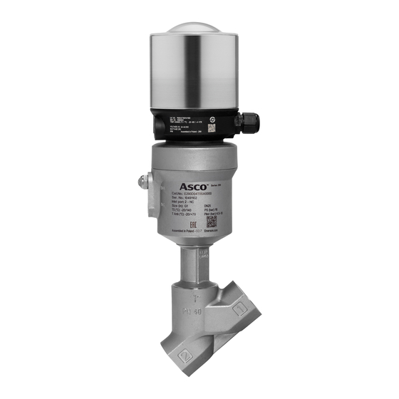
Signaling units on ASCO™ Series 290-390
DESCRIPTION AND OPERATION
Asco pressure operated valves normally close (NC) and
normally open (NO) type can be equipped with a compact
signaling unit enabling electrical monitoring of one or both
valve stem positions. This bracket consists of a support for
mounting reed switch and magneto-resistive (MR) detectors.
At both valve disc positions (open and closed), the magnet at
the end of the stem of the unit actuates, without contact, the
reed switch or creates a switching signal (magneto-resistive)
which provides an electrical end-of-travel signal.
Intended use
The signaling unit is intended to be used with Asco 290 and 390
Series pressure operated valve with actuators 32 mm to 125 mm
(except 32 mm and 50 mm NO plastic actuators).
INSTALLATION AND MAINTENANCE
The compact signaling unit is supplied installed on valve and
adjusted.
The compact signaling unit can be adapted to a valve origi-
nally not equipped with such features. perform all the stages
of installation, connection and adjustment described in this
document when supplied separately.
For installation and maintenance refer to the general safety
instructions.
Before any maintenance or installation operation, cut off the
electrical supply to the apparatus and check that the valve
is depressurized and drained. For work on the valve itself,
refer to the corresponding installation and maintenance
instructions.
NOTE: The assembled signaling unit meets IP65 when the
seal is correctly fitted (Reed detectors are IP67. Magneto-
resistive detectors are IP67 or IP69K).
! Do not install the signaling unit in an area where
welding is carried out, to avoid any magnetic distur-
bance. In such environments, preferably use electrical
units with mechanical contacts
Installation and adjustment of detectors
If possible, orient the valve actuator in a direction facilitating
connection of the detectors, then perform the operations
described under in case of unsetting during operation.
Install one or two detectors as appropriate.
1. Position the detector or detectors with the cable inlet ori-
ented upwards ( G and J).
2. Slide each detector, observing its fully up or fully down
position ( H
and
K).
3. Connect the connector or connectors then energise them.
Adjustment of the down position of the detector:
- Place the valve in the "closed" position.
. For a normally-closed valve, this is its rest position
. For a normally-open valve, apply the pilot pressure
(max. 10 bar)
- Manually move the detector until the LED comes on ( I).
Tighten the mounting screw at 270° (approx. 3/4 turn) while
maintaining the detector in place ( I).
- Check adjustment by number of operating tests.
Adjustment of up position of the detector:
- Place the valve in the "open" position.
. For a normally-closed valve, apply the pilot pressure
(max. 10 bar)
. For a normally-open valve, this is its rest position
- Manually move the detector until the LED comes on
( L). Tighten the mounting screw at 270° (approx.
3/4 turn) while maintaining the detector in place ( L).
- Check adjustment by number of operating tests.
Visit our website at Emerson.com/ASCO
Mounting of detector support on valve with dia. 32 mm
(stainless steel), 50, 63, 90 and 125 mm actuators:
Removal of the indicator cap
- 50 mm dia. plastic actuator: Unscrew and remove the cover
cap ( B1).
- 32 mm and 50 mm stainless steel actuators, and all versions
63 mm, 90 mm and 125 mm dia. actuators: Unscrew and
remove the sight dome with its seal ( B2) then unscrew
and remove the red indicator ( B).
! Pilot the NC valve control actuator beforehand to al-
low adaptation of the signaling support.
actuator
Catalog number
(mm)
Signaling unit support
32 50 63 90 125
•
•
-
-
-
-
-
P890AS0002A0000
•
•
•
-
-
-
-
P890AS0003A0000
•
•
•
-
-
-
-
•
•
P890AS0004A0000
-
-
-
-
-
• • •
-
-
-
-
P890AS0005A0000
1. The unit is supplied with a single plunger for all valve types
( C). The dia. 90 mm and 125 mm plastic actuator is sup-
plied with a spacer to be screwed to the plunger ( C1).
2. Screw the plunger manually into the valve stem ( D),
then tighten it to torque a ( E).
3. 63 mm, 90 mm and 125 mm actuators: Check that seal
item X on the support is greased (normal condition of sup-
ply). Install the seal in its housing in the control actuator
( F).
Screw on the signaling support and tighten to torque b
( F).
The support cannot be oriented.
Preventive maintenance
Visually inspect the signaling unit once a month.
Check:
- that there are no foreign objects on the support or between
the detectors,
- that the support is correctly secured against rotation.
Malfunctioning
In the event of failure to detect the open or closed position:
- if, during an operating cycle, the plunger does not move
or moves abnormally:
• check pressures (valve and pilot),
• check vibration of the valve and its control system,
- if the plunger moves correctly:
• check the electrical supply to the detectors,
• check the adjustment of the detector positions on the
support.
Removal and re-installation of the signaling unit
Removal is carried out in reverse order of installation, taking
the following precautions:
- disconnect the detectors from the electrical supply and
remove them,
To re-install, scrupulously follow the "Installation, connection
and adjustment" procedure described in this document.
2
Installation and Maintenance Instructions
EN
Signaling units on ASCO™ Series 290-390
CONNECTION AND ADJUSTMENT: Electrical connection must be carried out by qualified staff in accordance with local
Adjustment
See detector "up" and "down" position adjustment in this document. The detectors do not require any other adapter than
the signaling unit support.
REED SWITCH DETECTORS (2 WIRES)
SERIES REED
DETECTOR CHARACTERISTICS
Max. switching power
Switching voltage
Max. switching current
Short-circuit protection
Reverse polarity protection yes
Overload protection
Voltage drop (EN 60947-5-2)
Breakdown voltage
Contact resistance
Insulation resistance
Sensitivity
Response time
Repeatability
Working temperature
Degree of protection
Protection class
Signal indication
PUR lead outlet Ø 3 mm with
stripped ends, 2 wires 0.14 mm
.
brown wire = +
.
blue wire = -
3
1
2 m = P494A0021300A00
4
30 mm
5 m = P494A0021100A00
3
1
4
1
3
4
PUR lead outlet Ø 3 mm with
1
3
3-pin plug-in male connector +
3
1
4
4
screw Ø 8 mm (2 pins connected,
30 mm
30 mm
3
1
1 and 4)
3
1
4
4
0.3 m/12 in = P494A0021500A00
1
3
1
4
PUR lead outlet Ø 3 mm with
3
4
3
1
4
3-pin plug-in male connector +
30 mm
3
1
screw Ø 8 mm (2 pins connected,
4
1 and 3)
1
3
3
4
1
0.3 m/12 in = P494A0021600A00
4
PUR lead outlet Ø 3 mm re-
30 mm
3
1
sistant to cutting fluids, with
4
3-pin screw-type male connec-
1
3
4
tor, Ø M12 (2 pins connected,
1 and 4)
0.3 m/12 in = P494A0021700A00
standards and regulations.
MAGNETO-RESISTIVE SWITCH DETECTORS (MR) (3 WIRES)
SERIES PNP-NPN
DETECTOR CHARACTERISTICS
Max. switching power
DC = 5 W - AC = 5 VA
5..120V AC/DC or
Switching voltage
5..50/60V AC/DC
Max. switching current
Wiring
100 mA
Reverse polarity protection
no
Overload protection
Short-circuit protection
(without LED function)
Voltage drop (EN 60947-5-2)
no
< 5 volt
Max. leakage current
Max. allowable overvoltage
230 V DC
Sensitivity
0.2 ohm max.
Response time
10
8
ohms at 100 V
2.1 mTesla (21 Gauss)
Repeatability
Working temperature
0.1 ms opening
0.6 ms closing
Degree of protection
Protection class
< ± 0.2 mm
Signal indication
- 25°C , + 70°C
• Output protected against short-circuit as long as the out-
IP 67
put current is restricted to 0.1 A.
cable outlet: class II, M8 and
• Improper wire connection may prevent the detector from
M12 connection: class III
operating or even destroy it.
• It is recommended to install a protection diode (mounted
yellow diode (LED)
in parallel) on an inductive load in spite of the internal pro-
tection.
5 to 120 V AC/DC
• Polarities to be observed.
PNP
brown
1
2
black
4
blue
3
5 to 50 V AC
5 to 60 V DC
30 mm
25 mm
25 mm
25 mm
3
Visit our website at Emerson.com/ASCO
EN
3 W
10 to 30 V DC
100 mA
PNP - NPN
yes
yes
yes
< 1.5 V (I = 50 mA)
< 2.5 V (I = 100 mA)
< 50 µA
32 VCC max. (100 ms)
2 mTesla (20 Gauss)
110 µs opening
220 µs closing
< 0.2 mm
- 25°C , + 85°C
IP67 /IP69K
class III
yellow diode (LED)
NPN
brown
1
+
+
black
load
4
load
blue
_
_
3
10 to 30 V DC
PUR lead outlet Ø 3 mm,
stripped ends 3 wires 0.14 mm
2
.
Brown wire : +
.
Blue wire
: -
.
3
1
Black wire
: load
4
2 m/79 in (PNP) = P494A0022300A00
2 m/79 in (NPN) = P494A0022400A00
3
1
4
5 m/197 in (PNP) = P494A0022100A00
1
3
4
PUR lead outlet Ø 3 mm with
3
4
1
+
3-pin plug-in male + connector +
_
screw Ø M8
1
3
4
1
+
3
4
0.3 m/12 in (PNP) = P494A0022600A00
_
+
_
0.3 m/12 in (NPN) = P494A0022700A00
1
3
4
1
3
4
+
_
PUR lead outlet Ø 3 mm resist-
+
ant to cutting fluids, with 3-pin
_
1
screw-type male connector
3
4
Ø M12
+
_
0.3 m/12 in (PNP/IP67) = P494A0022800A00
0.3 m/12 in (PNP/IP69K) = P494A0022900A00
Advertisement

Related Manuals for Emerson ASCO 290 Series


Summary of Contents for Emerson ASCO 290 Series
- Page 1 3/4 turn) while maintaining the detector in place ( L). 1 and 4) 0.3 m/12 in (PNP/IP69K) = P494A0022900A00 - Check adjustment by number of operating tests. 0.3 m/12 in = P494A0021700A00 Visit our website at Emerson.com/ASCO Visit our website at Emerson.com/ASCO...
- Page 2 270° (environ 3/4 de tour) en maintenant le détecteur en 0,3 m/12 in (PNP/IP67) = P494A0022800A00 position ( L). 0,3 m/12 in (PNP/IP69K) = P494A0022900A00 - Vérifier le réglage par plusieurs essais de fonctionnement. Visit our website at Emerson.com/ASCO Visit our website at Emerson.com/ASCO...
- Page 3 Dokument beschriebene Verfahren "Installation, Anschluss und . Bei einem stromlos geöffneten Ventil ist dies die Ruhe- Einstellung". stellung - Bewegen Sie den Detektor manuell, bis die LED leuchtet ( L). Visit our website at Emerson.com/ASCO Visit our website at Emerson.com/ASCO...
- Page 4 . Para una válvula normalmente cerrada, aplique la pre- Para la reinstalación, siga escrupulosamente el procedimiento sión piloto (máx. 10 bar) de "Instalación, conexión y ajuste" descrito en este documento. Visit our website at Emerson.com/ASCO Visit our website at Emerson.com/ASCO...
- Page 5 Per il rimontaggio, seguire rigorosamente le procedure "Mon- 0,3 m/12 in (PNP/IP67) = P494A0022800A00 plicare la pressione di pilotaggio (max. 10 bar) taggio, collegamento e regolazione" descritte nel presente 0,3 m/12 in (PNP/IP69K) = P494A0022900A00 documento. Visit our website at Emerson.com/ASCO Visit our website at Emerson.com/ASCO...
- Page 6 0,3 m/12 in (PNP/IP67) = P494A0022800A00 . Voor een normaal geopende klep is dit de ruststand nauwkeurig op. 0,3 m/12 in (PNP/IP69K) = P494A0022900A00 - Beweeg de detector handmatig tot het LED aangaat Visit our website at Emerson.com/ASCO Visit our website at Emerson.com/ASCO...
- Page 7 ( L) skru-hannkontakt, Ø M12 (2 pinner 0,3 m/12 tommer (PNP/IP69K) = - Kontroller justeringen med en rekke driftstester. P494A0022900A00 tilkoblet, 1 og 4) 0,3 m/12 tommer = P494A0021700A00 Visit our website at Emerson.com/ASCO Visit our website at Emerson.com/ASCO...
- Page 8 – Utför ett antal användningstester för att kontrollera jus- (två stift anslutna, 1 och 4) 0,3 m/12 tum (PNP/IP67) = teringen. 0,3 m/12 tum = P494A0021700A00 P494A0022800A00 0,3 m/12 tum (PNP/IP69K) = P494A0022900A00 Visit our website at Emerson.com/ASCO Visit our website at Emerson.com/ASCO...
- Page 9 ( L). Kiristä kiinnitysruuvi 270° kulmaan (noin 3/4 0,3 m/12” = P494A0021700A00 kierrosta) pitäen samalla ilmaisinta paikallaan ( L). P494A0022800A00 – Tarkista säätö käyttötesteillä. 0,3 m/12” (PNP/IP69K) = P494A0022900A00 Visit our website at Emerson.com/ASCO Visit our website at Emerson.com/ASCO...
- Page 10 0,3 m/12 tommer (PNP/IP69K) = ( L). Spænd monteringsskruen 270° (ca. 3/4 om- P494A0022900A00 drejning), mens detektoren holdes på plads ( L). - Kontroller justeringen efter antallet af driftstest. Visit our website at Emerson.com/ASCO Visit our website at Emerson.com/ASCO...
- Page 11 . Para uma válvula normalmente fechada, aplique a pressão piloto (máx. 10 bar) . Para uma válvula normalmente aberta, esta é a posição de descanso - Mova manualmente o detetor até o LED ficar aceso Visit our website at Emerson.com/ASCO Visit our website at Emerson.com/ASCO...
- Page 12 - Τοποθετήστε τη βαλβίδα στην "ανοιχτή" θέση. κασία εγκατάστασης, σύνδεσης και ρύθμισης, όπως περιγράφεται 0,3 m/12 in (PNP/IP69K) = P494A0022900A00 . Για την κανονικά κλειστή βαλβίδα, εφαρμόστε την πιλοτική στο παρόν έγγραφο. πίεση (έως 10 bar) Visit our website at Emerson.com/ASCO Visit our website at Emerson.com/ASCO...
- Page 13 LED ( L). Utáhněte upevňovací šroub o 270 ° (cca. 0,3 m/12“ = P494A0021700A00 3/4 otáčky) při zachování snímače na místě ( L). P494A0022800A00 - Zkontrolujte nastavení několika provozními zkouškami. 0,3 m/12" (PNP/IP69K) = P494A0022900A00 Visit our website at Emerson.com/ASCO Visit our website at Emerson.com/ASCO...
- Page 14 0,3 m/12 cali (PNP/IP69K) = P494A0022900A00 dzić ciśnienie sterowania (maks. 10 barów) dury „montażu, podłączenia i regulacji” opisanej w niniejszym . W przypadku zaworu normalnie otwartego jest to pozycja dokumencie. spoczynkowa Visit our website at Emerson.com/ASCO Visit our website at Emerson.com/ASCO...
- Page 15 LED( L). Húzza meg a rögzítőcsavart 270°-ban (kb. 3/4 P494A0022800A00 0,3 m/12 hüvelyk = P494A0021700A00 fordulattal) és közben tartsa egy helyben az érzékelőt ( L). 0,3 m/12 hüvelyk (PNP/IP69K) = - Ellenőrizze a beállítást több üzemteszttel. P494A0022900A00 Visit our website at Emerson.com/ASCO Visit our website at Emerson.com/ASCO...
- Page 16 270° 270° 12 mm P4994406160N001 270° 270° 5-12-24-30 Inch.pounds Emerson Automation Fluid Control & Pneumatics Poland Sp. z o. o. ul. Kurczaki 132 93-331 Lodz POLAND Visit our website at Emerson.com/ASCO Visit our website at Emerson.com/ASCO...
- Page 17 3/4 turn) while maintaining the detector in place ( L). 1 and 4) 0.3 m/12 in (PNP/IP69K) = P494A0022900A00 - Check adjustment by number of operating tests. 0.3 m/12 in = P494A0021700A00 Visit our website at Emerson.com/ASCO Visit our website at Emerson.com/ASCO...
- Page 18 од ( L). Затяните крепежный винт на 270° (примерно на 0,3 м/12 in (PNP/IP67) = P494A0022800A00 3/4 оборота), удерживая при этом датчик на месте ( L). 0,3 м/12 in (PNP/IP69K) = P494A0022900A00 - Проверьте настройку, проведя несколько испытаний. Посетите наш сайт Emerson.com/ASCO Посетите наш сайт Emerson.com/ASCO...
- Page 19 ( L). Бұранданы детекторды орнында сақтаған кезде 0,3 м (PNP/IP67) = P494A0022800A00 270° (шамамен 3/4 айналым) шамасына бекітіңіз ( L). 0,3 м (PNP/IP69K) = P494A0022900A00 - Бірнеше пайдалану сынақтары арқылы реттеуді тексеріңіз. Emerson.com/ASCO мекенжайындағы веб-сайтымызға кіріп көріңіз Emerson.com/ASCO мекенжайындағы веб-сайтымызға кіріп көріңіз...
- Page 20 25 mm 带 3 引脚螺纹型公连接器 Ø M12 带 3 引脚螺纹型公连接器, Ø M12 ( 已 连接 2 个引脚: 1 和 4) 0.3 m/12 in (PNP/IP67) = P494A0022800A00 0.3 m/12 in (PNP/IP69K) = P494A0022900A00 0.3 m/12 in = P494A0021700A00 请访问我们的网站 Emerson.com/ASCO 请访问我们的网站 Emerson.com/ASCO...
- Page 21 Inch.pounds 5-12-24-30 世格流体控制(上海)有限公司 520546-001 A 世格流体控制(上海)有限公司 520546-001 A 中国•上海市松江区新桥镇新庙三路 480 号 邮编:201612 第3页,共5页 Emerson Automation Fluid Control & Pneumatics Poland Sp. z o. o. 中国•上海市松江区新桥镇新庙三路 480 号 邮编:201612 第3页,共5页 电话:(86-21)57071888 客户服务热线:800-820-2323 ul. Kurczaki 132 电话:(86-21)57071888 客户服务热线:800-820-2323 请访问我们的网站 Emerson.com/ASCO 网站:www.emerson.com Visit our website at Emerson.com/ASCO 网站:www.emerson.com...