Table of Contents
Advertisement
Quick Links
Advertisement
Table of Contents

Related Manuals for York YCUZ330A3


Summary of Contents for York YCUZ330A3
- Page 1 RecipPak CONDENSING UNITS AIR COOLED - RECIPROCATING HERMETIC INSTALLATION, OPERATION, MAINTENANCE Supersedes: 195.26-NM2 (394) Form 195.26-NM3 (197) 60 HZ MODELS YCUZ330A3, YCUZ440A3, YCUZ740B3, YCUZ770B3, YCUZ880B3 STYLE A* 26569A 200, 230, 460-3-60 *With EPROM 031-01096C013...
-
Page 2: Table Of Contents
DX central station air handling. They are designed for outdoor (roof or ground level) installation. The units are designed in accordance with UL (200, 230, 460-3-60), N.E.C., ASHRAE/ANSI STANDARD 15, The unit will be pressure-tested, evacuated and given and ASME Codes ARI 590. YORK INTERNATIONAL... -
Page 3: Nomenclature
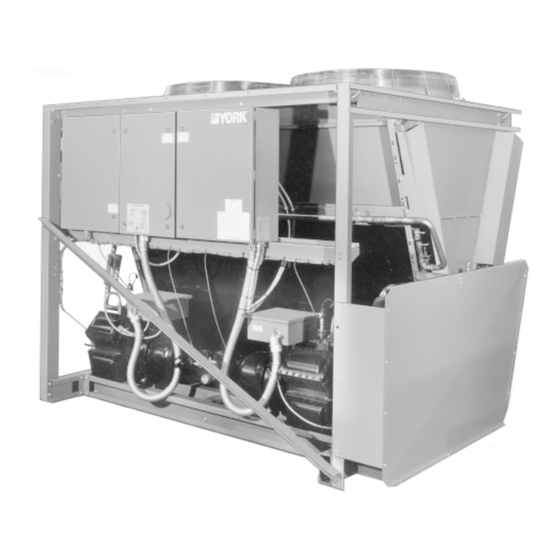
COMPRESSOR NOMENCLATURE “Z” MODELS Compressor Series No. of Cylinders (4, 6) Displacement No. of Steps of Unloading (0, 1, 2) Style B Motor Size Code Electrical Voltage Code Motor Vendor: L = Leroy Somer S = A.O. Smith YORK INTERNATIONAL... - Page 4 SUPPORT FRAME SHIPPING BRACE Z COMPRESSOR (2) GUARD 26569A SUCTION LINE (1 OF 2) COMPRESSOR TERMINAL BOX FILTER/DRYER LIQUID LINES STOP VALVES LIQUID LINES COMPRESSOR POWER WIRING HARNESS Z COMPRESSOR 26570A SUCTION VALVE FIG. 1 – UNIT COMPONENTS YORK INTERNATIONAL...
- Page 5 FORM 195.26-NM3 LIQUID LINES ( 1-1/8 OD ) CHARGING PORT SYS. 1 SYS. 2 26575A OIL PRESSURE TRANSDUCER Z COMPRESSOR OIL PUMP STOP VALVE FIG. 1 – UNIT COMPONENTS - CONTINUED YORK INTERNATIONAL...
- Page 6 TERMINAL BOX TERMINAL BOX DISCHARGE STOP VALVE CAPACITY CONTROL OIL PRESSURE SOLENOID ACCESS CONN. DATA LABEL OIL PUMP CRANKCASE HEATER 27294A(R) OIL LEVEL SIGHT GLASS OIL CHARGING VALVE 6 CYLINDER MODEL Z COMPRESSOR FIG. 2 – COMPRESSOR COMPONENTS YORK INTERNATIONAL...
-
Page 7: Operational Limitations
460-3-60 Z880B3 575-3-60 NOTES: 1. For lower or higher suction temperature applications, contact your YORK representative. 2. Operation below 25°F requires the Optional Low Ambient kit. 3. Operation above 116°F requires Optional High Ambient kit. PHYSICAL DATA MODEL YCU Z330A3... -
Page 8: Dimensions
Z770B3 Z880B3 44-3/32 13-13/16 3-1/8 ODS 3-1/8 ODS 1. Clearances – Recommended YORK required clearances to pre- vent condenser air recirculation and faulty operation of units are as follows: Side to wall - 5'-0" Rear to wall - 8'-0" Front to wall - 8'-0"... - Page 9 FORM 195.26-NM3 CONTROL/POWER PANEL DIMENSIONS CONTROL & POWER WIRING ENTRY (SEE BELOW) LD00566 YORK INTERNATIONAL...
-
Page 10: Electrical Data
UNIT POWER WIRING INCOMING WIRING RANGE COMPR. COMPR. COND MODEL DUAL ELEM MAX SIZE CODE FUSE SIZE DISCONNECT CKT BKR UNIT YORK SUPPLIED NON-FUSED HACR MINIMUM DISCONNECT (OPTIONAL) EACH MIN. MAX. TYPE Z330A3 (2)#6-250MCM (1)#1-600MCM OR (2) #1-250MCM 112 10.6... - Page 11 STANDARD UNIT NON-FUSED DISCONNECT SWITCH OPTION LD00884 LEGEND CODE Voltage Code (see page 7) Minimum Circuit Ampacity PW/LRA Part Wind Inrush Amps Running Load Amps Full Load Amps CKT BRK Circuit Breaker HACR Heating, Air Conditioning and Refrigeration YORK INTERNATIONAL...
-
Page 12: Installation
INSTALLATION WARNING To protect warranty, this equipment must be installed and serviced by an authorized YORK service mechanic or a qualified service person experienced in chiller installation. Installa- tion must comply with all applicable codes, particularly in regard to electrical wiring and other safety elements such as relief valves, HP cutout settings, design working pressures and ventilation requirements consistent with the amount and type of refrigerant charge. - Page 13 (See DIMENSIONS). 6. Take additional turns on mounts at low side or Mounting holes (11/16" dia.) are provided in the steel corner to level the equipment. channel for bolting the unit to its foundation. See DI- YORK INTERNATIONAL...
- Page 14 ISOLATOR AND DIMENSIONS LOAD POINTS (Al) MODEL NO. YCUZ330A3 1309 1309 VMC Isolator CP-1-27 CP-1-27 CP-1-32 CP-1-32 YCUZ440A3 1327 1327 VMC Isolator CP-1-25 CP-1-25 CP-1-27 CP-1-27 YCUZ740B3 1461 1461 VMC Isolator CP-1-25 CP-1-25 CP-1-27 CP-1-27 YCUZ770B3 1528 1528 VMC Isolator...
- Page 15 (3) Suction line velocity for oil return lines to facilitate servicing. (4) Liquid line pressure drop due to vertical rise YORK ASSUMES NO WARRANTY RESPONSIBILITY Refer to Table 2 (Recommended refrigerant line sizing) FOR SYSTEM OPERATION OR FAILURES DUE TO for the friction losses for both the suction and liquid IMPROPER PIPING OR PIPING DESIGN.
- Page 16 DESCRIPTION together as possible. CONDENSING UNIT SYSTEM #1 COMPRESSOR AND SUCTION CONNECTION 2. Filter driers and cores provided by YORK for field installa- SYSTEM #2 COMPRESSOR AND SUCTION CONNECTION tions by others. SYSTEM #1 SUCTION LINE VERTICAL RISER 3. Liquid line solenoid valves are required and may be ob-...
- Page 17 PRESSOR MUST NEVER BE REMOVED. See Fig. 7 the compressor or install a factory insulation kit when for terminal locations. they become available. Contact YORK Factory Mar- keting for availability. Zone Thermostat Start/Stop ELECTRICAL WIRING Connect SYS 1 to terminals 13 and 14 of TB3 (Fig.
-
Page 18: Wiring Diagram
Compressor terminals 1, 2, 3 are connected to terminals 7, 8, 9 in compressor terminal box on across-the-line start units and wires 100 thru 102 & 200 thru 202 are not supplied. 9. Canadian and International models may not require HACR-type circuit breakers. FIG. 6 – ELEMENTARY DIAGRAM YORK INTERNATIONAL... - Page 19 & including the zone thermostat for start/stop wired into the Alarm circuitry, or cy- cling contacts must be sup- pressed with YORK P/N 031- 00808-000 suppressor across the relay/contactor coil which activates the contacts. CAUTION: Control wiring connected to the...
- Page 20 1MP , COMPR. MOTOR PROTECTOR SYS. NO. 1 & NO. 2 1SOL, COMPR. IDENT. 2SOL LOADING SOLENOID VALVE SYS. NO. 1 & NO. 2 6 CYLINDER COMPR. LD00572 1TS - 15TS TRANSIENT SUPPRESSION FIG. 7 – SYSTEM WIRING YORK INTERNATIONAL...
- Page 21 FORM 195.26-NM3 COMPRESSOR COMPRESSOR (SYSTEM NO. 2) (SYSTEM NO. 1) LD00851 LD00852 FIG. 7 – (CONTINUED) YORK INTERNATIONAL...
- Page 22 NALS 1, 2, 3 ARE CONNECTED TO TERMINALS 7, TRANSIENT SUPPRESSORS 8, 9 IN COMPRESSOR TERMINAL BOX ON ______ ACROSS-THE-LINE START UNITS AND WIRES 100 WIRING BY YORK _ _ _ _ THRU 102 & 200 THRU 202 ARE NOT SUPPLIED. WIRING BY OTHERS OPTIONAL WIRING AND/OR COMPONENTS FIG.
- Page 23 FORM 195.26-NM3 CONNECTION DIAGRAM, ELEMENTARY BOX LD00847(D2) FIG. 8 – CONNECTION DIAGRAM (CONTINUED) YORK INTERNATIONAL...
-
Page 24: Unit Controls And Operation
Remote cycling of each refrigerant system can be ac- Keypad commands are acted upon by the micro to complished by user supplied dry contacts from remote change setpoints, cut-outs, scheduling, operating re- thermostats. quirements, and to provide displays. YORK INTERNATIONAL... - Page 25 SYSTEM #2 COMPRESSOR MOTOR OVERLOADS CONTACTORS TB1 - 115VAC SUPPLY, ALARM CONTACTS, AND EMERGENCY GROUND LUGS STOP CONNECTION POINT 26574A SYSTEM #2 SYSTEM #1 INCOMING POWER WIRING INCOMING POWER WIRING CONNECTION LUGS CONNECTION LUGS FIG. 10 – POWER PANEL YORK INTERNATIONAL...
- Page 26 FIG. 11 – CONTROL PANEL (EXTERIOR) POWER SUPPLY BOARD 2T TRANSFORMER RELAY OUTPUT BOARD #1 LOCATION OF OPTIONAL RELAY OUTPUT BOARD #2 MICROPROCESSOR TB3 - CONNECTIONS FOR FLOW SWITCH, LEAD/LAG SELECTOR, AND EMS/BAS CONTROLS 26573A FIG. 11 – CONTROL PANEL (INTERIOR) YORK INTERNATIONAL...
- Page 27 Oil Pressure: 0 PSID sponding display messages will be discussed in the Suction Pressure: 0 PSIG text which follows. Discharge Pressure: 0 PSIG Discharge Pressure Readout is an option. Without this option, the display will read a fixed value. YORK INTERNATIONAL...
- Page 28 Fig. 13 shows the location and verification of switch of 99999 starts can be logged on a system before the positioning of S1. counter will rollover. * Discharge Pressure Readout is an option. Without this option, the display will read a fixed value. YORK INTERNATIONAL...
- Page 29 C O N T R O L TOP VIEW NOTCH LD00574 LD00573 SIDE VIEW “OPEN” POSITION (LEFT SIDE OF SWITCH IS PUSHED DOWN) “CLOSED” POSITION (RIGHT SIDE OF SWITCH IS PUSHED DOWN) LD00575 26001A FIG. 13 – DIP SWITCH S1 AND EPROM LOCATION YORK INTERNATIONAL...
- Page 30 This mode will also be necessary to allow operation of options to This MUST be selected for “2” fan chillers where be developed in the future. fans are shared by both refrigerant circuits. YORK INTERNATIONAL...
- Page 31 This MUST be selected in all cases to assure proper fan cycling and chiller opertion. CLOSED: T W O S T A G E F A N C O N T R O L DO NOT USE under any circumstances. YORK INTERNATIONAL...
- Page 32 This message informs the operator that the “UNIT” The COMP RUNNING message indicates that the re- switch on the Control Panel is in the OFF position which spective compressor is running due to demand. will not allow the chiller to run. YORK INTERNATIONAL...
- Page 33 Reloading will take place when discharge pressure has dropped 60 PSIG below the threshold. Optional discharge pressure transducers must be in- stalled for this feature to operate. This is accomplished by adding the Discharge Pressure Readout option. YORK INTERNATIONAL...
- Page 34 C U R R E N T S Y S M O T O R C U R R E N T S Y S L L S V N O T S Y S L L S V N O T YORK INTERNATIONAL...
- Page 35 The ENTER key is also used to scroll through avail- the week. The day will advance a day at a time, each able data after any one of the following 4 keys is time the key is pressed. pressed: OPER PROGRAM DATA SET SCHEDULE HISTORY /HOLIDAY YORK INTERNATIONAL...
- Page 36 A I R T M P L O W GRAMMED WHEN COMMISSIONING THE CHILLER. C U T O U T 2 5 . 0 FAILURE TO PROPERLY PROGRAM THESE VALUES MAY CAUSE DAMAGE TO THE CHILLER OR OPERA- TION PROBLEMS. YORK INTERNATIONAL...
- Page 37 P S I G This cut-out is normally set at 130.0°F to allow opera- tion to the absolute maximum temperature capability The SUCTION PRESSURE UNLOAD point is a pro- of the electro-mechanical components. grammable limit designed to assure that suction gas YORK INTERNATIONAL...
- Page 38 Key in the number of steps as required and press the time, longer periods will allow even more heat dissipa- ENTER key. If 5 or 7 steps is programmed, the “0” key tion, reduce cycling, and possibly increase motor life. (05 or 07) must be pressed first. YORK INTERNATIONAL...
- Page 39 Two TIME digits must be entered for each of these items. There- A message showing the day, time and date will be dis- fore, a leading “0” may be required. played when the SET TIME key is pressed. YORK INTERNATIONAL...
- Page 40 The Holiday Schedule is only executed once by the ously programmed into other days. For scrolling through micro before it is erased from memory. This is done the days to view times programmed use the ADVANCE because in most cases a special Holiday Schedule is YORK INTERNATIONAL...
- Page 41 When the MANUAL OVERRIDE key is pressed, the designed so that if let on accidentally, the micropro- Daily Schedule programmed into the chiller will be ig- cessor will automatically return to the Daily Schedule. nored and the chiller will start-up when water tempera- YORK INTERNATIONAL...
- Page 42 S E T P O I N T P S I G by the user for the DX coil to operate within. As an P S I G example, all explanations will use a “Control Zone” of 50-60 PSIG. YORK INTERNATIONAL...
- Page 43 Separate timers for “load- UNLOADING WILL OCCUR ing” and “unloading” are implemented in software. The operation and duration of these timers is outlined on FIG. 15 – LOADING/UNLOADING WITH RESPECT the following page. TO THE CONTROL ZONE YORK INTERNATIONAL...
- Page 44 “Control Zone”. will count form that point if pressure rises form the “Control Zone” to “Above the Control Zone”. However, no unloading will take place as long as pressure stays in the “Above Con- trol Zone” area. YORK INTERNATIONAL...
- Page 45 “Below the Control Zone”. In some cases, the timer may be be- low 30 sec. on the transtion. In these cases, the timer will transition back to 60 sec. and restart. YORK INTERNATIONAL...
- Page 46 120 second period and The micro begins monitoring motor current after 3 sec- rises above cut-out before the timer times out, onds of operation. If motor current is exceeding 120% the system will continue to run. YORK INTERNATIONAL...
- Page 47 MP contact. A fault lock- prevents operation of a refrigerant system which has a out will result if safety thresholds are exceeded three leaking liquid line solenoid valve. times in a 90 minute period. YORK INTERNATIONAL...
- Page 48 C H I L L E R F A U L T : Anticipation controls are built into the software to pre- H I G H A M B I E N T T E M P vent safety shutdowns by automatically overriding tem- YORK INTERNATIONAL...
- Page 49 S Y S # 1 D S C H L I M I T I N G the keypad is not possible. S Y S # 2 D S C H L I M I T I N G YORK INTERNATIONAL...
- Page 50 A sample printout is shown in Fig. 19. History HISTORY The HISTORY key allows the operator to remotely ob- LD00640 tain a printout of information relating to the last 3 Safety FIG. 19 – OPERATING DATA PRINTOUT YORK INTERNATIONAL...
- Page 51 (storage area) for data related to each of the last 3 reveals other system conditions which actually caused safety shutdowns. the safety threshold to be exceeded (See Fig. 20). LD00641 NOTE: In actual printouts, this would be one continuous printout. FIG. 20 – HISTORY PRINTOUT (TYPICAL) YORK INTERNATIONAL...
- Page 52 This message informs the operator that the micro has This message provides a real time display of the time commanded the auxillary contacts (optional) for the remaining on the SYS 2 Unload Timer. The Unload Timer condenser water pump to close. YORK INTERNATIONAL...
- Page 53 O F F In the information that follows, a sample message along This message informs the operator of the number of with an explanation is provided for all available mes- forward running fans which are active on SYS 2. sages. YORK INTERNATIONAL...
- Page 54 The pressures shown indicate This message indicates the number of stages which the desired range of pressure which the system is to were loaded on SYS 1 at the time of the fault. maintain. YORK INTERNATIONAL...
- Page 55 NOTE: The micro will attempt to control the Hot Gas the time of the fault. This display will be a fixed value Solenoid Valve regardless of whether the op- unless the Discharge Pressure Readout is installed. tion is installed. YORK INTERNATIONAL...
- Page 56 Any inductive load devices (relay, contactor), supplied by the user which are connected to the dry contacts, SYSTEM SWITCHES MUST be suppressed at the load. Use YORK P/N 031- 00808-000 suppressor (not supplied). Failure to do this SYSTEM SWITCHES 1-4 are located on the Micropro- will result in nuisance faults and possible damage to the cessor Board (See Fig.
- Page 57 TIME-KEEPING, WILL BE MAINTAINED IN MEMORY REGARDLESS OF WHETHER THE CLOCK IS ON OR OFF AND REGARDLESS FIG. 22 – ALARM CONTACT CONNECTION OF THE LENGTH OF THE POWER FAILURE. LOCATION To disable the clock, place the jumper (Fig. 24) in the YORK INTERNATIONAL...
- Page 58 S1 on the Microprocessor Board must be placed in the OPEN position (page 30). The positioning of this switch can then be verified by pushing the OPTIONS key and verifying that “METRIC UNITS READOUT” is pro- grammed (page 28). 26001A FIG. 24 – CLOCK JUMPER REMOTE START/STOP YORK INTERNATIONAL...
- Page 59 (relay, contactor) is supplying these For operation below 25°F, a Low Ambient Kit MUST be contacts, the coil of the device must be suppressed with installed. See page 65. a user supplied YORK P/N 031-00808 suppressor. FAN CONTROL STRATEGY ABOVE 25°F AMBIENT LD00578(R)
-
Page 60: Compressor Capacity Control
MODEL CYLINDERS PER SYSTEM* cylinders. The unloader mechanism consists of a sole- YCUZ330A3 noid valve integrally mounted on the outside of the cover YCUZ440A3 plate, and an internal spring loaded piston. YCUZ740B3... - Page 61 If it is necessary to add oil, connect a SOLD BY: YORK oil pump to the oil charging valve, but do not tighten the flare nut on the delivery tubing. With the bottom (suction end) of the...
- Page 62 8. Program the Setpoint and Control Zone (CZ) by pressing the SUCTION PRESSURE SET - POINT key (Page 42). SYSTEM 2 PRESSURES Record the setpoint and control range: SUCTION: _______________ PSIG Setpoint _________________________ °F OIL: ____________________ PSIG Control Range ____________________ °F DISCHARGE: ____________ PSIG YORK INTERNATIONAL...
- Page 63 202 PSIG converted to 102°F If the unit has been functioning satisfactorily during the Minus Liquid Line Temperature –87°F initial operating period, it is ready for continuous op- Subcooling 15°F eration. Record: YORK INTERNATIONAL...
- Page 64 2 minute timer. This is the quence; however, compressors cannot start si- same timer that prevents an instantaneous start multaneously. There will always be a 1 minute after a power failure. delay between compressor starts. YORK INTERNATIONAL...
-
Page 65: Preventative Maintenance
It does not cover other related system components which may ANNUAL MAINTENANCE or may not be furnished by YORK. System com- ponents should be maintained according to the It is recommended that the following items be checked individual manufactures’... - Page 66 H. If the oil is clean and free of metal particles, refill the compressor with YORK oil “C”. To add NOTE: If suction or discharge valves are not seated properly, a 1000 micron vacuum can not be...
-
Page 67: Options
NOTE: Any inductive devices (contactor/relay coil) usually be tolerated. connected to these contacts must be sup- pressed with YORK P/N 031-00808-000 sup- Operation pressor supplied by others. The suppressor must be placed across the coil of the inductive The fundamental purpose of the Low Ambient Option device. - Page 68 This is identical to standard fan control by temperature contactors are energized, they will stay on until (page 59). This fan will de-energize if ambient tem- the discharge pressure of the system falls below perature drops below 40°F. YORK INTERNATIONAL...
- Page 69 General 1. Until discharge pressure reaches 320 PSIG, no The YORK Loadminder is a hot gas by-pass regulator system fans will operate. accessory which is factory mounted (field piping re- quired) when ordered. Its purpose is to provide further 2.
- Page 70 Zone Thermostat cycles off the (sooner) or in the counter clockwise direction to compressor. YORK INTERNATIONAL...
- Page 71 The discharge pressure unloading feature also becomes keypad. In addition to manual print selection, the micro usable when this option is installed (Page 37) as well panel will provide an automatic print-out whenever a as fan cycling by discharge pressure. YORK INTERNATIONAL...
- Page 72 “PRINT” KEY Sec- tion on Page 50. YORK recommends the field tested WEIGH-TRONIX IMP-24, Model 2600 printer. This is a compact low cost printer that is ideal for service work and data logging.
- Page 73 OPER DATA key. A snap-shot will be taken by the micro of current operating conditions. YORK assumes no warranty responsibility in the use These conditions will be stored in memory until they of the printer. This includes damages to the printer and can be transmitted to the printer and printed.
- Page 74 Touch up ex- posed metal parts to prevent rust. NOTE: Field modifications may need to be made to the grilles to accomodate piping. LD00584 L.H. END VIEW FIG. 33 – WIRE GRILLE INSTALLATION YORK INTERNATIONAL...
- Page 75 2. Attach Items 50, 51, 58, 62, 64, 65 & 66 before attaching grilles. 5. Trim grilles to suit wiring, water connections etc. 6. Notch out grilles as required when high amb.. sun shield option is used. R.H. END VIEW LD00585 FIG. 34 – WIRE GRILLE INSTALLATION YORK INTERNATIONAL...
- Page 76 2. Attach Items 20, 21, 25, 38, 39, 40 & 41 before attaching louver panels. LD00586 R.H. END VIEW NOTE: Field modifications may need to be made to the louvered panels to ac- commodate piping. LD00587 L.H. END VIEW FIG. 35 – LOUVERED ENCLOSURE INSTALLATION YORK INTERNATIONAL...
-
Page 77: Troubleshooting Chart
1. Low oil charge. 1. Oil level should be visible in either sight glass at Fault all times. Add YORK “C” oil if necessary. 2. Too much refrigerant-in oil, particularly 2. Check crankcase oil heater operation. (350 Watt on start-up. - Page 78 1. Low oil charge. 1. Oil level should be visible in either sight glass Oil Level at all times. Add YORK “C” oil if necessary. (Particularly on 2. Excessive flood back of liquid 2. Adjust Thermal Expansion Valve (TXV) or replace start-up) refrigerant.
- Page 79 FORM 195.26-NM3 LD00643 YORK INTERNATIONAL...
- Page 80 Proud Sponsor of the 1998 U.S. Olympic Team 36USC380 P.O. Box 1592, York, Pennsylvania USA 17405-1592 Subject to change without notice. Printed in USA Copyright © by York International Corporation 1997 ALL RIGHTS RESERVED Form 195.26-NM3 (197) Supersedes: 195.26-NM2 (394)