Table of Contents
Advertisement
Air-Cooled Scroll
Compressor Condensing Units
Installation, Operation, and
Supersedes: 150.63-NM9 (1220)
Form 150.63-NM9 (521)
Maintenance
035-22896-000
YCUL0020–YCUL0072
Air-Cooled Scroll Compressor Condensing Units
Style E (50 Hz and 60 Hz)
15 ton to 80 ton
50 kW to 280 kW
R-410A
Issue Date:
May 20, 2021
Products are produced at a
f a c i l i t y w h o s e q u a l i t y -
management systems are
ISO9001 certified.
Advertisement
Table of Contents
Troubleshooting

Related Manuals for York YCUL0020


Summary of Contents for York YCUL0020
- Page 1 Compressor Condensing Units Installation, Operation, and Supersedes: 150.63-NM9 (1220) Form 150.63-NM9 (521) Maintenance 035-22896-000 YCUL0020–YCUL0072 Air-Cooled Scroll Compressor Condensing Units Style E (50 Hz and 60 Hz) 15 ton to 80 ton 50 kW to 280 kW R-410A Issue Date:...
- Page 2 Form 150.63-NM9 Issue date: 5/20/2021 Important! Read before proceeding! General safety guidelines This equipment is a relatively complicated apparatus. which it is situated, as well as severe personal injury or During rigging, installation, operation, maintenance, death to themselves and people at the site. or service, individuals may be exposed to certain com- This document is intended for use by owner-authorized ponents or conditions including, but not limited to:...
- Page 3 Planned Service Agreement that leverages real time and generalized conditions. In lieu of the traditional and historical data, delivering performance reporting, maintenance program, a Johnson Controls YORK corrective actions required and data enabled guidance Conditioned Based Maintenance (CBM) program can for optimal operation and lifecycle assurance.
- Page 4 Form 150.63-NM9 Issue date: 5/20/2021 THIS PAGE IS INTENTIONALLY LEFT BLANK JOHNSON CONTROLS...
-
Page 5: Table Of Contents
Form 150.63-NM9 Issue date: 5/20/2021 Table of contents SECTION 1 – GENERAL EQUIPMENT INFORMATION AND SAFETY ............11 Introduction ..............................11 Compressors ..............................11 Condenser ..............................11 Refrigerant Circuit ............................11 Warranty ................................. 11 Safety and Quality ............................12 About this Manual ............................12 Misuse of Equipment ............................ - Page 6 Form 150.63-NM9 Issue date: 5/20/2021 Table of contents (cont’d) SECTION 5 – TECHNICAL DATA ........................41 Operational Limitations (English) ........................41 Physical Data (English) ..........................42 Physical Data (SI) ............................43 Electrical Data ..............................44 Electrical Notes and Legend .......................... 49 Wiring Diagrams .............................
- Page 7 Form 150.63-NM9 Issue date: 5/20/2021 Table of contents (cont’d) Compressor Run Status ..........................145 Alarm Status ..............................145 BAS/EMS Discharge Air Temperature Reset Using a Voltage or Current Signal ......... 146 SECTION 9 – SERVICE AND TROUBLESHOOTING ..................147 Clearing History Buffers..........................147 Service Mode ...............................
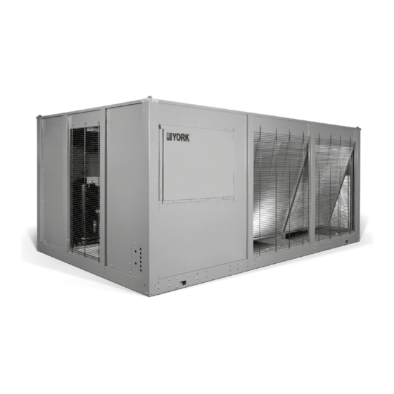
- Page 8 Form 150.63-NM9 Issue date: 5/20/2021 List of figures FIGURE 1 - YCUL Air-Cooled Scroll Compressor Condensing Unit ...............15 FIGURE 2 - Unit Components Front ........................20 FIGURE 3 - Control/Power Panel Components Single System Units ..............21 FIGURE 4 - Control/Power Panel Components Dual System Units ...............22 FIGURE 5 - Refrigerant Flow Diagram ........................27 FIGURE 6 - Process and Instrumentation Diagram ....................28 FIGURE 7 - Unit Rigging ............................29...
- Page 9 TABLE 20 - YCUL0045 – YCUL0072 Condenser Fan Control Using Discharge Pressure Only ......143 TABLE 21 - YCUL0020 – YCUL0072 Low Ambient Condenser Fan Control – Discharge Pressure Control ..144 TABLE 22 - YCUL0020 – YCUL0035 Low Ambient Condenser Fan Control – Discharge Pressure Control ..144 TABLE 23 - Compressor Operation –...
- Page 10 Form 150.63-NM9 Issue date: 5/20/2021 THIS PAGE IS INTENTIONALLY LEFT BLANK JOHNSON CONTROLS...
-
Page 11: Section 1 - General Equipment Information And Safety
Controls Service Center (see SECTION 6 – COM- driven, and positioned for vertical air discharge. The MISSIONING). fan guards are constructed of heavy-gauge, rust-resis- tant, PVC (polyvinyl chloride)-coated steel wire. • Only genuine YORK approved spare parts, oils, coolants, and refrigerants must be used. JOHNSON CONTROLS... -
Page 12: Safety And Quality
Form 150.63-NM9 SECTION 1 – GENERAL EQUIPMENT INFORMATION AND SAFETY Issue date: 5/20/2021 • All the scheduled maintenance operations detailed About this Manual in this manual must be performed at the specified The following terms are used in this document to alert times by suitably trained and qualified personnel the reader to areas of potential hazard. - Page 13 Form 150.63-NM9 SECTION 1 – GENERAL EQUIPMENT INFORMATION AND SAFETY Issue date: 5/20/2021 Structural Support Rotating Parts Structural support of the unit must be provided as in- Fan guards must be fitted at all times and not removed dicated in these instructions. Failure to provide probe- unless the power supply has been isolated.
- Page 14 Form 150.63-NM9 Issue date: 5/20/2021 THIS PAGE IS INTENTIONALLY LEFT BLANK JOHNSON CONTROLS...
-
Page 15: Section 2 - Product Description
Issue date: 5/20/2021 Section 2 – Product description Introduction General System Description YORK Air-Cooled Scroll Condensing Units are the Compressors perfect refrigeration components for all air condition- The condensing unit has suction-gas cooled, hermetic, ing applications that use DX central station air han- scroll compressors. -
Page 16: Microcomputer Control Center
• System discharge pressure outs through a separate printer (by others). • Discharge air temperature reset through a YORK Entry ISN DDC or Building Automation System (by This section is used to enter setpoints or modify system others) using the following: values. -
Page 17: Building Automation System Interface
Form 150.63-NM9 SECTION 2 – PRODUCT DESCRIPTION Issue date: 5/20/2021 • Anti-recycle timer status for each system • The standard unit capabilities include remote start-stop, remote discharge air temperature re- • Anti-coincident system start timer condition set through a PWM 4 mA to 20 mA or 0 VDC to 10 VDC input signal, or up to two stages of •... -
Page 18: Discharge Pressure Transducers And Readout Capability
Form 150.63-NM9 SECTION 2 – PRODUCT DESCRIPTION Issue date: 5/20/2021 Accessories and options Electrical Options Control Options Compressor Power Connections Ambient Kit (Low) Single-point terminal block connection(s) are provid- Units will operate to 25°F (-4°C). This factory mount- ed as standard. The following power connections are ed accessory includes all necessary components to available as factory mounted options. - Page 19 Form 150.63-NM9 SECTION 2 – PRODUCT DESCRIPTION Issue date: 5/20/2021 Post-Coated Dipped Condenser Coils Suction Pressure Transducers The unit’s coils are constructed with dipped-cured con- This transducer permits the unit to sense and display denser coils. This is the choice for corrosive applica- suction pressure.
-
Page 20: Figure 2 - Unit Components Front
Form 150.63-NM9 SECTION 2 – PRODUCT DESCRIPTION Issue date: 5/20/2021 Ultra Quiet Fan Vibration Isolators Lower RPM, 8-pole fan motors are used with steeper- Level adjusting, spring type 1 in. (25.4 mm) or seismic pitch fans on these factory mounted devices. deflection or neoprene pad isolators for mounting un- der unit base rails (Field-Mounted). -
Page 21: Figure 3 - Control/Power Panel Components Single System Units
Form 150.63-NM9 SECTION 2 – PRODUCT DESCRIPTION Issue date: 5/20/2021 Power panel components CIRCUIT BREAKER KEYPAD AND DISPLAY UNIT SWITCH COMPRESSOR CONTACTORS USER TERMINAL BLOCK LD28297 Figure 3 - Control/Power Panel Components Single System Units JOHNSON CONTROLS... -
Page 22: Figure 4 - Control/Power Panel Components Dual System Units
Form 150.63-NM9 SECTION 2 – PRODUCT DESCRIPTION Issue date: 5/20/2021 Power panel / control components TERMINAL BLOCK FAN FUSES CR1 / CR2 COMPRESSOR CONTACTS CTB1 LD28298 Figure 4 - Control/Power Panel Components Dual System Units JOHNSON CONTROLS... -
Page 23: Basic Unit
PIN Level :200 / 3 / 60 U : Unit :230 / 3 / 60 :Design Series YC :YORK Condensing :380 / 3 / 60 :460 / 3 / 60 :575 / 3 / 60 :380-415 / 3 / 50... - Page 24 Form 150.63-NM9 SECTION 2 – PRODUCT DESCRIPTION Issue date: 5/20/2021 Product identification number (PIN) (cont’d) FEATURE FEATURE DESCRIPTION OPTION OPTION DESCRIPTION No power capacitor required Power Factor Capacitor (19) Power capacitor required Special power capacitor required High ambient (standard) Ambient Kits (PIN 20) Both low and high ambient (low ambient kit required) Special ambient kit required No BAS reset/offset required...
- Page 25 Form 150.63-NM9 SECTION 2 – PRODUCT DESCRIPTION Issue date: 5/20/2021 Product identification number (PIN) (cont’d) FEATURE FEATURE DESCRIPTION OPTION OPTION DESCRIPTION No option required PIN 36 PIN 36 Special quote Crankcase heater standard Crankcase Heater (Pin 37) Special crankcase heater required No option required DWP (PIN 38) Special quote...
- Page 26 Form 150.63-NM9 SECTION 2 – PRODUCT DESCRIPTION Issue date: 5/20/2021 Product identification number (PIN) (cont’d) FEATURE FEATURE DESCRIPTION OPTION OPTION DESCRIPTION No option required PAINT PIN 53 Special quote No isolators required 1 In. deflection isolators required ISOL Vibration Isolators (PIN 54) Neoprene isolators required Seismic isolators required Special isolators required...
-
Page 27: Figure 5 - Refrigerant Flow Diagram
Form 150.63-NM9 SECTION 2 – PRODUCT DESCRIPTION Issue date: 5/20/2021 Refrigerant flow diagram LD04284A Figure 5 - Refrigerant Flow Diagram JOHNSON CONTROLS... -
Page 28: Figure 6 - Process And Instrumentation Diagram
Form 150.63-NM9 SECTION 2 – PRODUCT DESCRIPTION Issue date: 5/20/2021 Process and instrumentation diagram Control Functions: DV - Display Value Fans Fans CHT - Chilled Liquid Temperature Components: HPC - High Pressure Cutout Pressure Relief Valve (ZP180 Scroll Only) * LPC - Low Pressure Cutout HPL - High Pressure Load Limiting Service (Ball) Valve... -
Page 29: Section 3 - Handling And Storage
Form 150.63-NM9 Issue date: 5/20/2021 Section 3 – Handling and storage Delivery and Storage Unit Rigging To ensure consistent quality and maximum reliability, Use spreader bars to avoid lifting chains hitting the all units are tested and inspected before leaving the fac- unit. - Page 30 Form 150.63-NM9 SECTION 3 – HANDLING AND STORAGE Issue date: 5/20/2021 Moving the Condensing Unit Lifting Weights Before moving the unit, ensure that the installation site For details of weights and weight distribution, refer to is suitable for installing the unit and is easily capable the data shipped in the unit information packet and unit of supporting the weight of the unit and all associated nameplate.
-
Page 31: Section 4 - Installation
YORK Engineering Guide for the specific con- The units must be installed with sufficient clearances densing unit model. Sound blankets for the compres- for air entrance to the condenser coil, for air discharge sors and low sound fans are available. -
Page 32: Spring Isolators (Optional)
Form 150.63-NM9 SECTION 4 – INSTALLATION Issue date: 5/20/2021 If the ducts from two or more fans are to be combined Corrosive Environments into a common duct, back-flow dampers should be fit- Protection against corrosive environments is available ted in the individual fan ducts. This will prevent re- by supplying the units with either copbeforefin, cured circulation of air when only one of the fans is running. -
Page 33: Figure 8 - Wiring Options For Remotely Start Or Stop The Dual System Unit
Form 150.63-NM9 SECTION 4 – INSTALLATION Issue date: 5/20/2021 System Run Contacts Remote Emergency Cutoff Contacts are available to monitor system status. Normal- Immediate shutdown of the chiller can be accomplished ly-open auxiliary contacts from each compressor contac- by opening a field-installed dry contact to break the tor are wired in parallel with TB1 –... -
Page 34: Relief Valves
It is mum operating efficiencies. System piping should con- intended only as a safety switch, so it can- form to the YORK DX piping guide Form 50.40-ES2 not be jumped out. or ASHRAE refrigeration handbook guidelines. All piping design and installation is the responsibility of the user. -
Page 35: Table 1 - Fitting Equivalent Lengths
20% allowance is taken. calculated yield strength to a level below the system design. For more details, refer to ASHRAE Refrigeration Handbook, Chapter 2 and YORK DX Piping Guide YCUL Line Sizing Notes Form 50.40-ES2. The YCUL chiller has a maximum design working... -
Page 36: Table 3 - Miscellaneous Liquid Line Pressure Drops
7/8 in. for the optional factory mounted hot gas bypass valve. Note: Hot gas bypass is only available for refrigerant system number 1. 6. For more information, refer to either the YORK DX Piping Guide (Form 050.40-ES2) or the ASHRAE Refrigertion Handbook. -
Page 37: Oil Traps
25 ft (7.6 m) should be trapped liquid and suction lines. Read the notes under the table every 15 ft (4.6 m). and refer to YORK DX Piping Guide (Form 050.40- ES2) or ASHRAE Refrigeration Handbook for detailed For more details, refer to ASHRAE Refrigeration information. -
Page 38: Figure 9 - Single-Point Supply Connection - Terminal Block, Non-Fused Disconnect Switch
Form 150.63-NM9 SECTION 4 – INSTALLATION Issue date: 5/20/2021 Single-point supply connection – terminal block, non-fused disconnect switch, or circut breaker Power Panel Power Panel Power Panel Control Panel Control Panel Control Panel Terminal Block, Terminal Block, MICROPANEL MICROPANEL NF Disconnect SW NF Disconnect SW or Circuit Breaker or Circuit Breaker... -
Page 39: Figure 11 - Control Wiring
Form 150.63-NM9 SECTION 4 – INSTALLATION Issue date: 5/20/2021 Control wiring PWM INPUT (CAN ONLY BE USED WITH DISCHARGE AIR TEMP CONTROL) LOAD LIMIT INPUT AIR FLOW SWITCH AND REMOTE START/STOP SYSTEM 1 THERMOSTAT (SUCTION PRESSURE CONTROL ONLY) SYSTEM 2 THERMOSTAT (SUCTION PRESSURE CONTROL ONLY) CTB1 LD28295 POWER SUPPLY* 120V-1PH-60Hz L TO 2... - Page 40 Form 150.63-NM9 Issue date: 5/20/2021 THIS PAGE IS INTENTIONALLY LEFT BLANK JOHNSON CONTROLS...
-
Page 41: Section 5 - Technical Data
Form 150.63-NM9 Issue date: 5/20/2021 Section 5 – Technical data Operational limitations (English) Excessive flow will cause damage to the cooler. Do not exceed the maximum cooler flow. Special care should be taken when multiple chillers are fed by a single pump. NOTES: 1. -
Page 42: Physical Data (English)
Form 150.63-NM9 SECTION 5 – TECHNICAL DATA Issue date: 5/20/2021 Physical data (English) YCUL0020_ – YCIL0072_ 60 Hz Table 6 - Physical Data (English) MODEL NO. YCUL 0020EE 0024EE 0031EE 0035EE 0045EE 0051EE 0055EE 0065EE 0072EE Length (in.) 109.8 109.8 118.6 118.6 144.8... -
Page 43: Physical Data (Si)
Form 150.63-NM9 SECTION 5 – TECHNICAL DATA Issue date: 5/20/2021 Physical data (SI) YCUL0020_ – YCUL0072_ 50 Hz Table 7 - Physical Data (SI) MODEL NO. YCUL 0020EE 0024EE 0031EE 0035EE 0045EE 0051EE 0055EE 0065EE 0072EE Length (mm) 2788.7 2788.7 3012.4 3012.4 3677.9... -
Page 44: Electrical Data
Form 150.63-NM9 SECTION 5 – TECHNICAL DATA Issue date: 5/20/2021 Electrical data Ckt. 1 Number of fans Ckt. 2 Condenser Fans, Fan Power kW/fan Ultra Quiet Fan RPM Total Chiller L/s 9672 9672 18641.7 18641.7 20450.7 20450.7 20450.7 Table 8 - Micro Panel Power Supply OVER CURRENT PROTECTION, CONTROL UNIT VOLTAGE... - Page 45 Form 150.63-NM9 SECTION 5 – TECHNICAL DATA Issue date: 5/20/2021 Electrical notes 5. Circuit breakers must be UL listed and CSA certi- 1. Minimum Circuit Ampacity (MCA) is based on fied and maximum size is based on 225% of the 125% of the rated load amps for the largest mo- rated load amps for the largest motor plus 100% tor plus 100% of the rated load amps for all other...
- Page 46 Form 150.63-NM9 SECTION 5 – TECHNICAL DATA Issue date: 5/20/2021 Electrical data YCUL0020 - YCUL0072 SYSTEM # 1 SYSTEM # 2 MINIMUM CHILLER MIN N/F DUAL COMPR 1 COMPR 2 COMPR 1 COMPR 2 CIRCUIT DUAL MODEL VOLT HZ DISC SW...
- Page 47 Form 150.63-NM9 SECTION 5 – TECHNICAL DATA Issue date: 5/20/2021 Electrical data YCUL0020 - YCUL0072 SYSTEM # 1 SYSTEM # 2 MINIMUM CHILLER MIN N/F DUAL COMPR 1 COMPR 2 COMPR 1 COMPR 2 CIRCUIT DUAL MODEL VOLT HZ DISC SW...
-
Page 48: Table 10 - Lug Ranges
Form 150.63-NM9 SECTION 5 – TECHNICAL DATA Issue date: 5/20/2021 Table 10 - Lug Ranges FIELD WIRING LUGS FIELD WIRING LUGS FIELD WIRING LUGS TERMINAL BLOCK (STD) NF DISC. SWITCH (OPT) CIRCUIT BREAKER (OPT) YCUL HZ VOLT LUGS/ LUGS/ LUGS/ LUG WIRE RANGE LUG WIRE RANGE LUG WIRE RANGE... -
Page 49: Electrical Notes And Legend
Note Well {See Note} - KM Suppressor) Wiring And Items Shown Thus Are - KCR Control Relay Standard York Accessories Pump Contactor Part Wiring And Items Shown Thus Are Not - KP (Including Coil Suppressor) Supplied By York - KT... - Page 50 No controls {relays etc.} Should be mounted in any section of the control panel. Additionally, control wiring not connected to the YORK control panel should not be run through the panel. If these precautions are not followed, electrical noise could cause malfunctions or damage to the unit and its controls.
- Page 51 Form 150.63-NM9 SECTION 5 – TECHNICAL DATA Issue date: 5/20/2021 Electrical notes and legend (cont’d) Optional compressor manual motors starters (standard on CE units). See sheet 3 of connection diagram for power input options. Alternate connections shown for different two speed motor types. Only fitted on systems with a maximum of 4 fans.
-
Page 52: Wiring Diagrams
Form 150.63-NM9 SECTION 5 – TECHNICAL DATA Issue date: 5/20/2021 Wiring diagrams YCUL0020-YCUL0035 Low sound YCUL0031-0035 Ultra low sound (460 V and 380-415 V 50 Hz) Figure 12 - Control Wiring Diagram, Single Circuit, IPU II JOHNSON CONTROLS... - Page 53 Form 150.63-NM9 SECTION 5 – TECHNICAL DATA Issue date: 5/20/2021 JOHNSON CONTROLS...
- Page 54 Form 150.63-NM9 SECTION 5 – TECHNICAL DATA Issue date: 5/20/2021 YCUL0031-0035 Ultra low sound (200 V, 230 V, 380 V, and 575 V) Figure 13 - Control Wiring Diagram, Single Circuit, IPU II JOHNSON CONTROLS...
-
Page 55: Figure 13 - Control Wiring Diagram, Single Circuit, Ipu Ii
Form 150.63-NM9 SECTION 5 – TECHNICAL DATA Issue date: 5/20/2021 JOHNSON CONTROLS... -
Page 56: Figure 14 - Control Wiring Diagram, Dual Circuit, Ipu Ii
Form 150.63-NM9 SECTION 5 – TECHNICAL DATA Issue date: 5/20/2021 YCUL0045-YCUL0055 Low sound YCUL0045-0072 Ultra low sound (460 V and 380-415 V 50 Hz) Figure 14 - Control Wiring Diagram, Dual Circuit, IPU II JOHNSON CONTROLS... - Page 57 Form 150.63-NM9 SECTION 5 – TECHNICAL DATA Issue date: 5/20/2021 JOHNSON CONTROLS...
-
Page 58: Figure 15 - Control Wiring Diagram, Dual Circuit, Ipu Ii
Form 150.63-NM9 SECTION 5 – TECHNICAL DATA Issue date: 5/20/2021 YCUL0065-YCUL0072 Low sound YCUL0045-0072 Ultra low sound (200 V, 230 V, 380 V and 575 V) Figure 15 - Control Wiring Diagram, Dual Circuit, IPU II JOHNSON CONTROLS... - Page 59 Form 150.63-NM9 SECTION 5 – TECHNICAL DATA Issue date: 5/20/2021 JOHNSON CONTROLS...
-
Page 60: Figure 16 - Control Wiring Diagram, Details, Single Circuit
Form 150.63-NM9 SECTION 5 – TECHNICAL DATA Issue date: 5/20/2021 YCUL0020-YCUL0035 Low sound YCUL0031-0035 Ultra low sound 035-20964-103 REV C Notes: 1. Field wiring to be in accordance with the current edition of the National Electrical Code as well as all other applicable codes and speci- fications. - Page 61 Form 150.63-NM9 SECTION 5 – TECHNICAL DATA Issue date: 5/20/2021 JOHNSON CONTROLS...
-
Page 62: Figure 17 - Control Wiring Diagram, Details, Dual Circuit
Form 150.63-NM9 SECTION 5 – TECHNICAL DATA Issue date: 5/20/2021 YCUL0045-YCUL0072 Low sound YCUL0045-0072 Ultra low sound 035-20880-103 REV C Notes: 1. Field wiring to be in accordance with the current edition of the National Electrical Code as well as all other applicable codes and speci- fications. - Page 63 Form 150.63-NM9 SECTION 5 – TECHNICAL DATA Issue date: 5/20/2021 JOHNSON CONTROLS...
-
Page 64: Figure 18 - Power Wiring, Single Circuit
Form 150.63-NM9 SECTION 5 – TECHNICAL DATA Issue date: 5/20/2021 Power options connection diagrams YCUL0020-YCUL0024 Low sound (200 V, 230 V, 380 V, 460 V, and 575 V) Figure 18 - Power Wiring, Single Circuit JOHNSON CONTROLS... - Page 65 Form 150.63-NM9 SECTION 5 – TECHNICAL DATA Issue date: 5/20/2021 JOHNSON CONTROLS...
-
Page 66: Figure 19 - Power Wiring, Single Circuit
Form 150.63-NM9 SECTION 5 – TECHNICAL DATA Issue date: 5/20/2021 Power options connection diagrams YCUL0020-YCUL0024 Low sound (380-415 V/3/50) Figure 19 - Power Wiring, Single Circuit JOHNSON CONTROLS... - Page 67 Form 150.63-NM9 SECTION 5 – TECHNICAL DATA Issue date: 5/20/2021 JOHNSON CONTROLS...
-
Page 68: Figure 20 - Power Wiring, Single Circuit
Form 150.63-NM9 SECTION 5 – TECHNICAL DATA Issue date: 5/20/2021 YCUL0031-YCUL0035 Low sound YCUL0031-YCUL0035 Ultra low sound (460 V and 380-415 V/3/50) Figure 20 - Power Wiring, Single Circuit JOHNSON CONTROLS... - Page 69 Form 150.63-NM9 SECTION 5 – TECHNICAL DATA Issue date: 5/20/2021 JOHNSON CONTROLS...
-
Page 70: Figure 21 - Power Wiring, Single Circuit
Form 150.63-NM9 SECTION 5 – TECHNICAL DATA Issue date: 5/20/2021 YCUL0031-YCUL0035 Ultra low sound (200 V, 230 V, 380 V, and 575 V) Figure 21 - Power Wiring, Single Circuit JOHNSON CONTROLS... - Page 71 Form 150.63-NM9 SECTION 5 – TECHNICAL DATA Issue date: 5/20/2021 JOHNSON CONTROLS...
-
Page 72: Figure 22 - Power Wiring, Dual Circuit
Form 150.63-NM9 SECTION 5 – TECHNICAL DATA Issue date: 5/20/2021 YCUL0045-YCUL0055 Low sound YCUL0045-0072 Ultra low sound (460 V and 380-415 V 50 Hz) Figure 22 - Power Wiring, Dual Circuit JOHNSON CONTROLS... - Page 73 Form 150.63-NM9 SECTION 5 – TECHNICAL DATA Issue date: 5/20/2021 JOHNSON CONTROLS...
-
Page 74: Figure 23 - Power Wiring, Dual Circuit
Form 150.63-NM9 SECTION 5 – TECHNICAL DATA Issue date: 5/20/2021 YCUL0065-YCUL0072 Low sound YCUL0045-0072 Ultra low sound (200 V, 230 V, 380 V, and 575 V) Figure 23 - Power Wiring, Dual Circuit JOHNSON CONTROLS... - Page 75 Form 150.63-NM9 SECTION 5 – TECHNICAL DATA Issue date: 5/20/2021 JOHNSON CONTROLS...
-
Page 76: Figure 24 - Connection Wiring, Single Circuit
Form 150.63-NM9 SECTION 5 – TECHNICAL DATA Issue date: 5/20/2021 YCUL0020-YCUL0024 Low sound (200 V, 230 V, 380 V, 460 V, and 575 V) Figure 24 - Connection Wiring, Single Circuit JOHNSON CONTROLS... - Page 77 Form 150.63-NM9 SECTION 5 – TECHNICAL DATA Issue date: 5/20/2021 JOHNSON CONTROLS...
-
Page 78: Figure 25 - Connection Wiring, Single Circuit
Form 150.63-NM9 SECTION 5 – TECHNICAL DATA Issue date: 5/20/2021 YCUL0020-YCUL0024 Low sound (380-415 V/3/50) Figure 25 - Connection Wiring, Single Circuit JOHNSON CONTROLS... - Page 79 Form 150.63-NM9 SECTION 5 – TECHNICAL DATA Issue date: 5/20/2021 JOHNSON CONTROLS...
-
Page 80: Figure 26 - Connection Wiring, Single Circuit
Form 150.63-NM9 SECTION 5 – TECHNICAL DATA Issue date: 5/20/2021 YCUL0031-YCUL0035 Low sound YCUL0031-YCUL0035 Ultra low sound (460 V and 380-415 V/3/50) Figure 26 - Connection Wiring, Single Circuit JOHNSON CONTROLS... - Page 81 Form 150.63-NM9 SECTION 5 – TECHNICAL DATA Issue date: 5/20/2021 JOHNSON CONTROLS...
-
Page 82: Figure 27 - Connection Wiring, Single Circuit
Form 150.63-NM9 SECTION 5 – TECHNICAL DATA Issue date: 5/20/2021 YCUL0031-YCUL0035 Ultra low sound (200 V, 230 V, 380 V, and 575 V) Figure 27 - Connection Wiring, Single Circuit JOHNSON CONTROLS... - Page 83 Form 150.63-NM9 SECTION 5 – TECHNICAL DATA Issue date: 5/20/2021 JOHNSON CONTROLS...
-
Page 84: Figure 28 - Connection Wiring, Dual Circuit
Form 150.63-NM9 SECTION 5 – TECHNICAL DATA Issue date: 5/20/2021 YCUL0045-YCUL0055 Low sound YCUL0045-0072 Ultra low sound (460 V and 380-415 V 50 Hz) Figure 28 - Connection Wiring, Dual Circuit JOHNSON CONTROLS... - Page 85 Form 150.63-NM9 SECTION 5 – TECHNICAL DATA Issue date: 5/20/2021 JOHNSON CONTROLS...
-
Page 86: Figure 29 - Connection Wiring, Dual Circuit
Form 150.63-NM9 SECTION 5 – TECHNICAL DATA Issue date: 5/20/2021 YCUL0065-YCUL0072 Low sound YCUL0045-0072 Ultra low sound (200 V, 230 V, 380 V, and 575 V) Figure 29 - Connection Wiring, Dual Circuit JOHNSON CONTROLS... - Page 87 Form 150.63-NM9 SECTION 5 – TECHNICAL DATA Issue date: 5/20/2021 JOHNSON CONTROLS...
-
Page 88: Dimensions (English)
SECTION 5 – TECHNICAL DATA Issue date: 5/20/2021 Dimensions (English) Dimensions – YCUL0020 to 0072 (ENGLISH) All dimensions in English unless otherwise noted NOTE: Placement on a level surface of free of obstructions (including snow, for winter operation) or air circulation ensures rated performance, reliable operation, and ease of maintenance. - Page 89 Form 150.63-NM9 SECTION 5 – TECHNICAL DATA Issue date: 5/20/2021 Dimensions – YCUL0020 to 0072 (ENGLISH) 60 HZ MODEL 0020EE 0024EE 0031EE 0035EE 0045EE 0051EE 0055EE 0065EE 0072EE Length 109.79 109.79 118.6 118.6 144.8 144.8 148.8 148.8 153.6 Width 44.7 44.7...
- Page 90 Form 150.63-NM9 SECTION 5 – TECHNICAL DATA Issue date: 5/20/2021 Dimensions – YCUL0020 to 0072 (SI) All dimensions in English unless otherwise noted NOTE: Placement on a level surface of free of obstructions (including snow, for winter operation) or air circulation ensures rated performance, reliable operation, and ease of maintenance.
- Page 91 Form 150.63-NM9 SECTION 5 – TECHNICAL DATA Issue date: 5/20/2021 Dimensions – YCUL0020 to 0072 (SI) 50 HZ MODEL 0020EE 0024EE 0031EE 0035EE 0045EE 0051EE 0055EE 0065EE 0072EE Length 2788.7 2788.7 3012.4 3012.4 3677.9 3677.9 3779.5 3779.5 3901.4 Width 1135.4 1135.4...
-
Page 92: Clearances
Form 150.63-NM9 SECTION 5 – TECHNICAL DATA Issue date: 5/20/2021 Clearances (2 m) (1.3 m) LD13243 Notes: 1. No obstructions allowed above the unit. 2. Only one adjacent wall may be higher than the unit. 3. Adjacent units should be 10 ft (3 m) apart. Figure 30 - Unit Clearances –... -
Page 93: Weight Distribution And Isolator Mounting Positions
Form 150.63-NM9 SECTION 5 – TECHNICAL DATA Issue date: 5/20/2021 Weight distribution and isolator mounting positions General Weights of specific chiller models vary significantly as Whenever the isolator option is ordered, the isolators options are added. As a result, total weights, weights at will be shipped loose with the chiller. -
Page 94: Isolator Locations (English)
Form 150.63-NM9 SECTION 5 – TECHNICAL DATA Issue date: 5/20/2021 Isolator locations (English) 60 Hz model YCUL0020EE YCUL0024EE YCUL0031EE YCUL0035EE 104.2 104.2 113.3 113.3 Isolator location dimensions 43.3 43.3 43.3 43.3 Figure 32 - Isolator Locations, 60 Hz JOHNSON CONTROLS... -
Page 95: Isolator Locations (Si)
Form 150.63-NM9 SECTION 5 – TECHNICAL DATA Issue date: 5/20/2021 Isolator locations (SI) 50 Hz model YCUL0020EE 3YCUL0024EE YCUL0031EE YCUL0035EE 431.8 431.8 431.8 431.8 2646.7 2646.7 2877.8 2877.8 Isolator location dimensions 27.9 27.9 27.9 27.9 1099.8 1099.8 1099.8 1099.8 Figure 33 - Isolator Locations, 50 Hz JOHNSON CONTROLS... -
Page 96: Isolation Information
Form 150.63-NM9 SECTION 5 – TECHNICAL DATA Issue date: 5/20/2021 Isolation information One inch deflection spring isolator cross-reference 5/8" Ø1/2" H" C" T" B" L" D" W" LD13759A DIMENSION DATA (IN.) MOUNT TYPE 7-3/4 6-1/2 4-3/4 5-5/8 10-1/2 9-1/4 7-3/4 9/16 MODEL NUMBER RATED CAPACITY (LB) -
Page 97: One Inch Deflection Spring Isolators Installation Instructions
Form 150.63-NM9 SECTION 5 – TECHNICAL DATA Issue date: 5/20/2021 One inch deflection spring isolators installation instructions 1. Read instructions in their entirety before begin- 5. Place equipment on top of isolators making sure ning installation. that mounting holes of the equipment line up with isolator positioning pin (“H”). -
Page 98: Two Inch Deflection Seismic Isolator Cross-Reference
Form 150.63-NM9 SECTION 5 – TECHNICAL DATA Issue date: 5/20/2021 Two inch deflection seismic isolator cross-reference 1-1/8" 5" 5/8" 2-3/4" 2-3/4" 12" 3/8" GAP 5/8-11UNC Ø3/4" TYP. (4) TYP.(4) 3/4" 7/8" 1/2" LIMIT STOP & 8-3/8" OPER. HEIGHT 12-1/4" 14" 3-1/2"... -
Page 99: Seismic Isolator Installation And Adjustment
Form 150.63-NM9 SECTION 5 – TECHNICAL DATA Issue date: 5/20/2021 Seismic isolator installation and adjustment 1. Read instructions in their entirety before begin- isolator with a minimum of 3/8 fillet welds 2 in. ning installation. long at 3 in. on center for a minimum total weld of 10 in. -
Page 100: Durulene Isolator Cross-Reference
Form 150.63-NM9 SECTION 5 – TECHNICAL DATA Issue date: 5/20/2021 Durulene isolator cross-reference RD-Style Isolators Notes: 1. All dimensions are inches, interpreted beforeANSI Y14. MOLDED 2. See next page for installation instructions. DURULENE 3. Mount molded in weather resistant duralene compound as ø... -
Page 101: Installation Of Durulene Vibration Isolators
Form 150.63-NM9 SECTION 5 – TECHNICAL DATA Issue date: 5/20/2021 Installation of durulene vibration isolators 1. Read instructions in their entirety before begin- 4. Bolt or anchor all isolators to supporting structure ning installation. utilizing base thru holes (“B”). 2. Isolators are shipped fully assembled and are to be 5. - Page 102 Form 150.63-NM9 Issue date: 5/20/2021 THIS PAGE IS INTENTIONALLY LEFT BLANK JOHNSON CONTROLS...
-
Page 103: Section 6 - Commissioning
Johnson Controls Au- To add oil to a circuit: thorized personnel. 1. Connect a YORK hand oil pump (Part No. 470- 10654-000) to the 1/4 in. oil charging valve with a length of clean hose or copbeforeline, but do not tighten the flare nut. -
Page 104: Preparation - Power On
Form 150.63-NM9 SECTION 6 – COMMISSIONING Issue date: 5/20/2021 Grounding Switch settings Verify that the unit’s protective ground terminal(s) are Ensure that the condensing unit OFF/ON UNIT switch correctly connected to a suitable grounding point. En- at the bottom of the keypad is OFF. Place the optional sure that all unit internal ground connections are tight. -
Page 105: Equipment Pre-Startup And Startup Checklist
Form 150.63-NM9 SECTION 6 – COMMISSIONING Issue date: 5/20/2021 Equipment Pre-Startup and Startup Checklist AIR-COOLED SCROLL COMPRESSOR CONDENSING UNITS Supersedes: 150.63-CL2 (1013) Form 150.63-CL2 (319) STARTUP CHECKLIST EQUIPMENT PRE-STARTUP AND STARTUP CHECKLIST CUSTOMER: ____________________________________ JOB NAME: ____________________________________ ADDRESS: _____________________________________ LOCATION: ____________________________________ PHONE: ________________________________________ CUSTOMER ORDER NO: _________________________ JCI TEL NO: _____________________... - Page 106 Form 150.63-NM9 SECTION 6 – COMMISSIONING Issue date: 5/20/2021 FORM 150.63-CL2 ISSUE DATE: 03/12/2019 TABLE 1 - SETPOINTS ENTRY LIST Place the Unit Switch in the control panel to the “ON” position. As each compressor cycles ON, en- OPTIONS sure that the discharge pressure rises and the suc- tion pressure decreases.
- Page 107 Form 150.63-NM9 SECTION 6 – COMMISSIONING Issue date: 5/20/2021 FORM 150.63-CL2 ISSUE DATE: 03/12/2019 D. CHECKING SUPERHEAT AND SUBCOOLING When adjusting the expansion valve (TXV only), the adjusting screw should be turned not more than one The subcooling temperature of each system can turn at a time, allowing sufficient time (approximately be calculated by recording the temperature of the 15 minutes) between adjustments for the system and...
- Page 108 Form 150.63-NM9 Issue date: 5/20/2021 THIS PAGE IS INTENTIONALLY LEFT BLANK JOHNSON CONTROLS...
-
Page 109: Section 7 - Unit Controls
Introduction Microprocessor board The Microprocessor Board is the controller and deci- The YORK Millenium MicroComputer Control Cen- sion maker in the control panel. System inputs such ter is a microprocessor based control system designed as pressure transducers and temperature sensors are to provide the entire control for the liquid condensing connected directly to the Microprocessor Board. -
Page 110: Unit Switch
Form 150.63-NM9 SECTION 7 – UNIT CONTROLS Issue date: 5/20/2021 Unit switch Battery back-up A unit ON/OFF switch is just underneath the keypad. The Microprocessor Board contains a Real Time Clock This switch allows the operator to turn the entire unit integrated circuit chip with an internal battery backup. - Page 111 Form 150.63-NM9 SECTION 7 – UNIT CONTROLS Issue date: 5/20/2021 Status key 00066VIP Unit status D A I L Y S C H E D U L E Pressing the STATUS key will enable the operator to S H U T D O W N determine current unit operating status.
- Page 112 Form 150.63-NM9 SECTION 7 – UNIT CONTROLS Issue date: 5/20/2021 occur when the discharge pressure gets within 15 psig S Y S C O M P S R U N of the programmed discharge pressure cutout. This will S Y S C O M P S R U N only happen if the system is fully loaded and will shut...
- Page 113 Form 150.63-NM9 SECTION 7 – UNIT CONTROLS Issue date: 5/20/2021 The Suction Pressure Cutout is a software cutout that S Y S P U M P I N G D O W N helps protect the unit from a coil freeze-up or compres- S Y S P U M P I N G D O W N...
- Page 114 Form 150.63-NM9 SECTION 7 – UNIT CONTROLS Issue date: 5/20/2021 The compressor is also equipped with a discharge Unit safeties temperature sensor for the purpose of sensing inter- Unit safeties are faults that cause all running compres- nal scroll temperature. This sensor protects the scrolls sors to be shut down.
- Page 115 Form 150.63-NM9 SECTION 7 – UNIT CONTROLS Issue date: 5/20/2021 If a low battery is detected, it should be replaced as Unit warning soon as possible. The programmed values will all be The following messages are not unit safeties and will lost and the unit will be prevented from running on the not be logged to the history buffer.
-
Page 116: Table 11 - Status Key Messages Quick Reference List
Form 150.63-NM9 SECTION 7 – UNIT CONTROLS Issue date: 5/20/2021 Status key messages Table 11 - Status Key Messages Quick Reference List STATUS KEY MESSAGES General Messages Fault Messages System Safeties Unit Safeties Unit Warnings Unit Switch Off Shutdown Remote Controlled System X High Disch Pressure Low Ambient Temp Low Battery... - Page 117 Form 150.63-NM9 SECTION 7 – UNIT CONTROLS Issue date: 5/20/2021 Display/Print keys 00067VIP The DISPLAY/PRINT keys allow the user to retrieve able under the OBeforeDATA key in the order that system and unit information that is useful for moni- they are displayed. The ↓ (DOWN) arrow key scrolls toring unit operation, diagnosing potential problems, through the displays in the order they appear below: troubleshooting, and commissioning the unit.
- Page 118 Form 150.63-NM9 SECTION 7 – UNIT CONTROLS Issue date: 5/20/2021 S Y S = 1 1 5 . 1 P S I G L O A D T I M E R S E C = 3 O 5 . 0 P S I G U N L O A D T I M E R...
- Page 119 1, then for system 2. toring may be via ISN. The first message indicates the system and the associ- ISN – YORK Talk via ISN allows remote load ated compressors which are running. limiting and temperature reset through an ISN system.
-
Page 120: Table 12 - Operation Data
A sample Operating Data printout is shown below. (Note: System 2 Discharge & Suction Pressure Not all values are printed for all models.) YORK INTERNATIONAL CORPORATION *System X Accumulated Hours MILLENNIUM CONDNESING UNIT UNIT STATUS... - Page 121 The difference is that the Daily Schedule is not printed in the history print and the header will be as follows. YORK INTERNATIONAL CORPORATION MILLENNIUM CONDENSING UNIT SAFETY SHUTDOWN NUMBER 1 SHUTDOWN @ 3:56PM...
- Page 122 Form 150.63-NM9 SECTION 7 – UNIT CONTROLS Issue date: 5/20/2021 History displays L O C A L / R E M O T E M O D E The HISTORY key gives the user access to many unit X X X X X X X X X and system operating parameters at the time of a unit or system safety shutdown.
- Page 123 Form 150.63-NM9 SECTION 7 – UNIT CONTROLS Issue date: 5/20/2021 S Y S X X X X P S I G L O W A M B I E N T T E M P R A N G E + / - X X X P S I G C U T O U T...
- Page 124 Form 150.63-NM9 SECTION 7 – UNIT CONTROLS Issue date: 5/20/2021 Displays for System 1 starting with SYS X NUMBER S Y S X X X X P S I G OF COMPS RUNNING X through SYS X AMPS = X X X X P S I G XXX.X VOLTS = X.X will be displayed first, fol- lowed by displays for System 2.
- Page 125 Form 150.63-NM9 SECTION 7 – UNIT CONTROLS Issue date: 5/20/2021 Entry keys 00068VIP The ENTRY keys allows the user to view, change Enter/Adv key programmed values. The ENTRY keys consist of an The ENTER/ADV key must be pushed after any change ↑...
- Page 126 Form 150.63-NM9 SECTION 7 – UNIT CONTROLS Issue date: 5/20/2021 Setpoints keys 00069VIP Programming of the cooling setpoints, daily schedule, L O C A L D I S C H A R G E and safeties is accomplished by using the keys located A I R T E M P C O N T R O L...
- Page 127 Form 150.63-NM9 SECTION 7 – UNIT CONTROLS Issue date: 5/20/2021 On two system units, each system is controlled inde- R E M O T E S U C T pendently of each other according to its own setpoint P R E S S U R E C O N T R O L and cooling range, so there will be two similar displays;...
- Page 128 Form 150.63-NM9 SECTION 7 – UNIT CONTROLS Issue date: 5/20/2021 The low limit, high limit, and default values for the The times may be set using the same procedure as de- keys under “SETPOINTS” are listed in Table 14. scribed above for the days of the week. After chang- ing the meridian of the stop time, pressing the ENTER/ Schedule/Advance Day key ADV key will advance the schedule to the following...
- Page 129 Form 150.63-NM9 SECTION 7 – UNIT CONTROLS Issue date: 5/20/2021 If the optional discharge pressure transducer is not in- F A N C O N T R O L stalled, this programmable safety would not apply. It P R E S S U R E = X X X P S I G should be noted that every system has a mechanical high pressure cutout that protects against excessive The Fan Control On-Pressure is the programmed pres-...
- Page 130 Form 150.63-NM9 SECTION 7 – UNIT CONTROLS Issue date: 5/20/2021 A single system condensing unit MUST For example, if fan and compressor RLA’s total 100A: have a jumbeforebetween terminals 5 V x 100 A 625 VA 1.25 2.8 V 13 - 17 on terminal block CTB1. If the 225 A 225 A jumbeforeis not installed, the unit will...
-
Page 131: Table 13 - Cooling Setpoints Programmable Limits And Defaults
Form 150.63-NM9 SECTION 7 – UNIT CONTROLS Issue date: 5/20/2021 Table 13 - Cooling Setpoints Programmable Limits and Defaults SETPOINT VALUE LOW LIMIT HIGH LIMIT DEFAULT 45.0 °F 70.0°F 55.0°F Discharge air temp. setpoint 7.2°C 21.1°C 12.7°C 3.0°F 10.0°F 5.0°F Discharge air temp. -
Page 132: Table 15 - Setpoints Quick Reference List
Form 150.63-NM9 SECTION 7 – UNIT CONTROLS Issue date: 5/20/2021 Table 15 - Setpoints Quick Reference List ObeforeData quick reference list Table 15 on page 132 provides a quick reference of the setpoints list for the SETPOINTS keys. SETPOINTS KEYS Cooling Setpoints Key Schedule/ Program Mode... - Page 133 Form 150.63-NM9 SECTION 7 – UNIT CONTROLS Issue date: 5/20/2021 Unit keys OPTIONS CLOCK 00070VIP Options key This turns system 1 OFF There are many user programmable options under the OPTIONS key. The OPTIONS key is used to scroll S Y S S W I T C H O F F through the list of options by repeatedly pressing the...
- Page 134 Form 150.63-NM9 SECTION 7 – UNIT CONTROLS Issue date: 5/20/2021 Option 4 – Local/Remote Control Type Option 7 – Lead/Lag Type (two system units only) L O C A L R E M O T E M O D E L L O C A L L E A D / L A G C O N T R O L...
- Page 135 Form 150.63-NM9 SECTION 7 – UNIT CONTROLS Issue date: 5/20/2021 Option 9 – Manual Override Mode Option 11 – Power Fail Restart M A N U A L O V E R R I D E M O D E P O W E R F A I L R E S T A R T...
- Page 136 Form 150.63-NM9 SECTION 7 – UNIT CONTROLS Issue date: 5/20/2021 Option 14 – Refrigerant Type F L A S H C A R D U P D A T E E N A B L E D R E F R I G E R A N T T Y P E R - 4 0 7 C Press the ENTER key and the following message will...
- Page 137 Form 150.63-NM9 SECTION 7 – UNIT CONTROLS Issue date: 5/20/2021 Option 18 – Hot Gas Bypass Type Clock The Hot Gas Bypass Type must be programmed based The CLOCK display shows the current day, time, and on the option installed. Some chillers will not have hot date.
-
Page 138: Table 16 - Options Key Programming Quick Reference List
Form 150.63-NM9 SECTION 7 – UNIT CONTROLS Issue date: 5/20/2021 Table 16 - Options Key Programming Quick Reference List Options Key Expansion Valve Type (Press Options Key (Thermoplastic or Electric) to Adv.) (Programmed Under Service Display Language Mode, Viewable Only) Must be Programmed for Thermostatic System Switches... -
Page 139: Section 8 - Unit Operation
Form 150.63-NM9 Issue date: 5/20/2021 Section 8 – Unit operation Capacity control Discharge pressure limit controls To initiate the start sequence of the unit, all run permis- The discharge pressure limit controls unload a system sive inputs must be satisfied (air proving/remote start/ before it reaches a safety limit due to high load or dirty stop switch), and no unit or system faults exist. -
Page 140: Figure 40 - Discharge Air Temperature Control
Form 150.63-NM9 SECTION 8 – UNIT OPERATION Issue date: 5/20/2021 20 sec. 30 sec. 60 sec. control range 60 sec. unloading unloading unloading (no compressor staging) loading 51.5°F 52.5°F 53.0°F 55.0°F 57.0° (10.8°C) (11.4°C) (11.7°C) (12.8°C) (13.9°C) Low Limit Setpoint High limit Discharge Air Temperature Control –... -
Page 141: Suction Pressure Control
Form 150.63-NM9 SECTION 8 – UNIT OPERATION Issue date: 5/20/2021 Suction pressure control If the suction pressure falls below the Setpoint High The setpoint in Suction Pressure Control is the suction pressures each individual system on the condensing Limit and greater than the Setpoint Low Limit, load- ing and unloading do not occur. -
Page 142: System Lead/Lag
Form 150.63-NM9 SECTION 8 – UNIT OPERATION Issue date: 5/20/2021 System lead/lag Anti-coincidence timer (Discharge Air Temp Control Only) This timer is not present on single-system units. Two timing controls are present in software to ensure com- Lead/lag between systems may be selected to help pressors within a circuit or between systems, do not start equalize average run hours between systems on con- simultaneously. -
Page 143: Figure 42 - Ycul0045 - Ycul0072 Fan Location (Typical)
Form 150.63-NM9 SECTION 8 – UNIT OPERATION Issue date: 5/20/2021 Table 19 - YCUL0020 – YCUL0072 Condenser Fan Control Using Outdoor Ambient Temperature and Discharge Pressure (Discharge pressure controls will not function unless the optional discharge pressure transducer is installed) -
Page 144: Table 21 - Ycul0020 - Ycul0072 Low Ambient Condenser Fan Control - Discharge Pressure Control
Form 150.63-NM9 SECTION 8 – UNIT OPERATION Issue date: 5/20/2021 Condenser fan control - YCUL0020 – YCUL0072 Table 21 - YCUL0020 – YCUL0072 Low Ambient Condenser Fan Control – Discharge Pressure Control I/O BOARD FAN # CONTACTOR OUTPUT STAGE SYS 1... -
Page 145: Load Limiting
Form 150.63-NM9 SECTION 8 – UNIT OPERATION Issue date: 5/20/2021 Simultaneous operation of Remote Load Load limiting Limiting and EMS-PWM Temperature Load Limiting is a feature that prevents the unit from Reset (described on following pages) loading beyond the desired value. Two and four com- cannot occur. -
Page 146: Bas/Ems Discharge Air Temperature Reset Using A Voltage Or Current Signal
Form 150.63-NM9 SECTION 8 – UNIT OPERATION Issue date: 5/20/2021 BAS/EMS discharge air temperature reset using a voltage or current signal If a 4 mA to 20 mA signal is supplied, it is applied to The Remote Reset Option allows the Control Center of terminals A+ and A- and jumbeforeJP1 on the I/O the unit to reset the discharge air temperature setpoint board must be installed between pin 1 and 2. -
Page 147: Section 9 - Service And Troubleshooting
Form 150.63-NM9 Issue date: 5/20/2021 Section 9 – Service and troubleshooting The following is the order of outputs that will appear as Clearing history buffers the ENTER/ADV key is pressed: The history buffers may be cleared by pressing the HISTORY key and then repeatedly pressing the UP SYS 1 COMP 1 STATUS TB7-2 IS: arrow key until you scroll past the last history buffer SYS 1 LLSV STATUS TB7-3 IS:... -
Page 148: Service Mode - Condensing Unit Configuration
Form 150.63-NM9 SECTION 9 – SERVICE AND TROUBLESHOOTING Issue date: 5/20/2021 Service mode – condensing unit Service mode – analog and digital inputs configuration After entering Service Mode (PROGRAM ↑↑ ↓↓), After the Outputs are displayed, the next group of dis- all digital and analog inputs to the microboard can be plays relate to unit configuration and start/hour coun- viewed by pressing the OBeforeDATA key. -
Page 149: Control Inputs/Outputs
Form 150.63-NM9 SECTION 9 – SERVICE AND TROUBLESHOOTING Issue date: 5/20/2021 sure input is connected to plug 7 – pin 10 (J7-10) on Table 25 - I/O Digital Outputs the I/O board. It indicates that the voltage is 2.1 VDC TB7-2 SYS 1 Compressor 1 which corresponds to 81 psig (5.6 barg) suction pres-... -
Page 150: Figure 43 - Microboard Layout
Form 150.63-NM9 SECTION 9 – SERVICE AND TROUBLESHOOTING Issue date: 5/20/2021 I/O BOARD BOARD TB10 LD12721 Figure 43 - Microboard Layout JOHNSON CONTROLS... -
Page 151: Checking Inputs And Outputs
Form 150.63-NM9 SECTION 9 – SERVICE AND TROUBLESHOOTING Issue date: 5/20/2021 Checking inputs and outputs Table 28 - Outdoor Air Sensor Temperature/Voltage/ Correlation Digital inputs VOLTAGE See the unit wiring diagram. All digital inputs are con- TEMP °F (SIGNAL INPUT TEMP °C nected to J13-1 of the I/O board. -
Page 152: Table 29 - Discharge Air Temp. Sensor Temperature/Voltage/Resistance Correlation
Form 150.63-NM9 SECTION 9 – SERVICE AND TROUBLESHOOTING Issue date: 5/20/2021 Table 29 - Discharge Air Temp. Sensor Temperature/ Discharge air temperature sensor Voltage/Resistance Correlation J6-5 = +5 VDC regulated supply to sensor. TEMP °F VOLTAGE RESISTANCE TEMP °C J6-8 = VDC input signal to the microboard. -
Page 153: Table 30 - Pressure Transducers
Form 150.63-NM9 SECTION 9 – SERVICE AND TROUBLESHOOTING Issue date: 5/20/2021 System 2 discharge transducer Table 30 - Pressure Transducers J9-6 = +5 VDC regulated supply to transducer. 0-400 PSIG SUCTION 0-650 PSIG DISCHARGE PRESSURE PRESSURE J9-11 = VDC input signal to the microboard. See the TRANSDUCER TRANSDUCER formula above for voltage readings that correspond to... -
Page 154: Figure 44 - I/O Board Relay Contact Architecture
Form 150.63-NM9 SECTION 9 – SERVICE AND TROUBLESHOOTING Issue date: 5/20/2021 Each output is controlled by the microprocessor by Digital outputs switching 120 VAC to the respective output connection See the unit wiring diagram and Figure 44. The digital energizing contactors, evaporator heater, and solenoids outputs are located on TB7, TB8, and TB9 and TB-10 according to the operating sequence (see Figure 44). -
Page 155: Figure 45 - Printer To Microboard Electrical Connections
A printout is obtained by pressing the PRINT key on The part number for the printer that is packaged spe- the keypad and then pressing either the OBeforeDATA cifically for YORK is P/N 950915576. The cable to key or HISTORY key. connect the printer can either be locally assembled from the parts listed, or ordered directly from WEIGH- TRONIX under part number 287-040018. - Page 156 Form 150.63-NM9 SECTION 9 – SERVICE AND TROUBLESHOOTING Issue date: 5/20/2021 Troubleshooting Table 31 - Troubleshooting PROBLEM CAUSE SOLUTION 1. No 115 VAC to 24 VAC 1a. Check wiring and fuse 1FU. Transformer. 1b. Check wiring emergency stop contacts 5 to L of TB1 Terminal Block.
-
Page 157: Table 31 - Troubleshooting
Form 150.63-NM9 SECTION 9 – SERVICE AND TROUBLESHOOTING Issue date: 5/20/2021 Table 31 - Troubleshooting (cont’d) PROBLEM CAUSE SOLUTION 1. Compressor internal motor 1. Verify refrigerant charge is not low. Verify protector (MP) open. superheat setting of 10°F to 15°F (5.6°C to 8.3°C). - Page 158 Form 150.63-NM9 Issue date: 5/20/2021 THIS PAGE IS INTENTIONALLY LEFT BLANK JOHNSON CONTROLS...
-
Page 159: Section 10 - Maintenance
Use U5 is the Real Time Clock chip located on the 031- YORK “V” oil when adding oil. 02630 IPU II board that maintains the date/time and stores customer programmed setpoints. The Real Time Oil analysis Clock is a 128K bram, P/N 031-02565-000. -
Page 160: Bacnet, Modbus, And Yorktalk 2 Communications
Form 150.63-NM9 SECTION 10 – MAINTENANCE Issue date: 5/20/2021 BACnet, Modbus, and YorkTalk 2 Communications See Figure 46 on page 161 for TB1, TB2 and TB3 Data can be read and in some cases modified using a locations. serial communication BACnet, Modbus or YorkTalk 2 network connection. -
Page 161: Figure 46 - Micro Panel Connections
Form 150.63-NM9 SECTION 10 – MAINTENANCE Issue date: 5/20/2021 035-02550-xxx I/O Board Figure 46 - Micro Panel Connections The following table shows the minimum, maximum, and default values. Table 32 - Minimum, Maximum, and Default Values DESCRIPTION MINIMUM MAXIMUM DEFAULT DE MODIFIER ADDRESS 41943 DE MODIFIER OFFSET... -
Page 162: Table 33 - Values Required For Bas Communication
Form 150.63-NM9 SECTION 10 – MAINTENANCE Issue date: 5/20/2021 The table below shows set-up requirements for each communication protocol. Table 33 - Values Required for Bas Communication PROTOCOL SETTING DESCRIPTION BACNET MS/TP MODBUS RTU5 YORKTALK 2 DE MODIFIER ADDRESS 0 to 41943(3) DE MODIFIER OFFSET 0 to 99(4) P1 PROTOCOL... - Page 163 Form 150.63-NM9 SECTION 10 – MAINTENANCE Issue date: 5/20/2021 BACnet and Modbus communications Communications data map notes (See Table 35 on page 164) Chiller data that can be read and modified using spe- cific BACnet or Modbus Register Addresses; and the 1.
-
Page 164: Table 35 - Bacnet And Modbus Communications Data Map
Form 150.63-NM9 SECTION 10 – MAINTENANCE Issue date: 5/20/2021 Table 35 - BACnet and Modbus Communications Data Map JOHNSON CONTROLS... - Page 165 Form 150.63-NM9 SECTION 10 – MAINTENANCE Issue date: 5/20/2021 Table 35 - BACnet and Modbus Communications Data Map (cont’d) JOHNSON CONTROLS...
- Page 166 Form 150.63-NM9 SECTION 10 – MAINTENANCE Issue date: 5/20/2021 Table 35 - BACnet and Modbus Communications Data Map (cont’d) JOHNSON CONTROLS...
- Page 167 Form 150.63-NM9 SECTION 10 – MAINTENANCE Issue date: 5/20/2021 Table 35 - BACnet and Modbus Communications Data Map (cont’d) JOHNSON CONTROLS...
-
Page 168: Table 36 - Yorktalk 2 Communications Data Map
Form 150.63-NM9 SECTION 10 – MAINTENANCE Issue date: 5/20/2021 YorkTalk 2 Communications Transmitted Data After receiving a valid transmission from the Micro- Received Data (Control Data) Gateway or E-Link, the unit will transmit either op- The unit receives 8 data values from the MicroGate- erational data or history buffer data depending on the way or E-Link. - Page 169 Form 150.63-NM9 SECTION 10 – MAINTENANCE Issue date: 5/20/2021 Table 36 - YorkTalk 2 Communications Data Map JOHNSON CONTROLS...
- Page 170 Form 150.63-NM9 SECTION 10 – MAINTENANCE Issue date: 5/20/2021 Table 36 - YorkTalk 2 Communications Data Map (cont’d) JOHNSON CONTROLS...
- Page 171 Form 150.63-NM9 SECTION 10 – MAINTENANCE Issue date: 5/20/2021 Table 36 - YorkTalk 2 Communications Data Map (cont’d) JOHNSON CONTROLS...
- Page 172 Form 150.63-NM9 SECTION 10 – MAINTENANCE Issue date: 5/20/2021 Table 36 - YorkTalk 2 Communications Data Map (cont’d) JOHNSON CONTROLS...
- Page 173 Form 150.63-NM9 SECTION 10 – MAINTENANCE Issue date: 5/20/2021 Table 36 - YorkTalk 2 Communications Data Map (cont’d) JOHNSON CONTROLS...
- Page 174 Form 150.63-NM9 SECTION 10 – MAINTENANCE Issue date: 5/20/2021 Table 36 - YorkTalk 2 Communications Data Map (cont’d) JOHNSON CONTROLS...
- Page 175 Form 150.63-NM9 SECTION 10 – MAINTENANCE TEMPERATURE CONVERSION CHART Issue date: 5/20/2021 Temperature conversion chart Temperature Conversion Chart - Temperature Conversion Chart - Actual Temperatures Differential Temperatures ° F ° C °C °F ° F ° C °C °F -17.8 -0.4 -15.6 -13.3...
- Page 176 Form 150.63-NM9 SECTION 10 – MAINTENANCE Issue date: 5/20/2021 R410A Pressure temperature chart PSIG TEMP ˚F PSIG TEMP ˚F JOHNSON CONTROLS...
- Page 177 Form 150.63-NM9 Issue date: 5/20/2021 Notes JOHNSON CONTROLS...
- Page 178 5000 Renaissance Drive, New Freedom, Pennsylvania USA 17349 1-800-524-1330 Subject to change without notice. Printed in USA Copyright © by Johnson Controls 2021 www.johnsoncontrols.com ALL RIGHTS RESERVED Form 150.63-NM9 (521) Issue Date: May 20, 2021 Supersedes: 150.63-NM9 (1220)