ADTRAN T200 H4TU-R Installation And Maintenance Practice
Adtran network device brochure
Hide thumbs
Also See for T200 H4TU-R:
- Specifications (2 pages) ,
- Troubleshooting manual (2 pages) ,
- Installation and maintenance practice (28 pages)
Table of Contents
Advertisement
CONTENTS
1. General...................................................................................... 1
2. Installation ................................................................................ 2
3. Connections .............................................................................. 5
4. HDSL4 System Testing ............................................................ 5
5. Front Panel Operation............................................................... 7
6. Control Port Operation.............................................................. 7
7. HDSL4 Deployment Guidelines............................................. 18
8. Maintenance............................................................................ 23
9. Specifications.......................................................................... 23
10. Warranty and Customer Service ............................................. 23
Appendix A. HDSL4 Loopbacks.............................................. A-1
TABLES
Table 1. ADTRAN Unit Compatability........................................ 1
Table 2. H2TU-R Enclosure Compatibility .................................. 2
Table 3. Compliance Codes .......................................................... 2
Table 4. Front Panel Indicators..................................................... 3
Table 5. Provisioning Options ...................................................... 4
Table 6. Attenuation limits ......................................................... 18
Table 7. Range Limits: 26 Gauge / 70°F / PIC .......................... 18
Table 8. Range Limits: 24 Gauge / 70°F / PIC .......................... 18
Table 9. Single Pair DC Resistance Value.................................. 19
Table 10. HDSL4 Insertion Loss Values ...................................... 22
Table 11. Single Span and First Segment of Repeatered Loop .... 22
Table 12. Second or Third Segment of Repeatered Loop............. 22
Table 13. Troubleshooting Guide ................................................. 23
Table 14. HDSL4 T200 H4TU-R Specifications.......................... 24
Table A-1. HDSL4 Loopback Control Codes............................ A-2
Table A-2. Loopback Control Codes ......................................... A-3
1. GENERAL
The ADTRAN 4-wire T200 HDSL4 transceiver unit for
the remote end (H4TU-R), P/N 1223424L2, is a
network terminating unit used to deploy an HDSL4 T1
circuit using 4-wire metallic facilities. See
This version of the H4TU-R works with multiple list
versions of the HDSL4 transceiver unit for the central
office (H4TU-C) and repeater (H4R) as listed in
Table
1.
Revision History
This is the initial release of this document. Future
revisions to this document will be explained in this
subsection.
61223424L2-5A
HDSL4 T200 H4TU-R
Installation and Maintenance Practice
Figure
1.
Trademarks: Any brand names and product names included in this document are
trademarks, registered trademarks, or trade names of their respective holders.
R
S
2
3
2
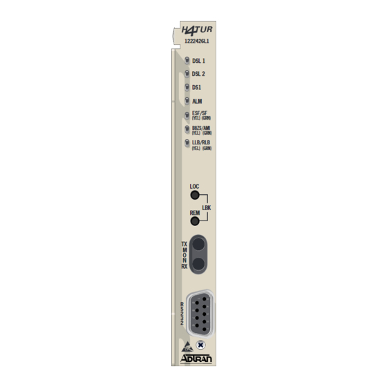
Figure 1. ADTRAN HDSL4 T200 H4TU-R
Table 1. ADTRAN Unit Compatability
Unit Number
Description
122x401L1 or L2
220 H4TU-C
122x403L1 or L2
DDM+ H4TU-C
122x404L1 or L2
3192 H4TU-R
118141xL1
Total Access H4TU-C
122x441L1
T200 H4R
122x445L1
239 H4R
NOTE: x = any generic release number
Section 61223424L2-5A
Issue 1, December 2003
CLEI Code: T1L497PC_ _
1223424L2
LOCAL
DSL 1
DSL 2
DS1
ALM
LOC
LBK
REM
TX
TX
M
O
N
RX
RX
1
Advertisement
Table of Contents

Related Manuals for ADTRAN T200 H4TU-R


Summary of Contents for ADTRAN T200 H4TU-R
-
Page 1: Table Of Contents
Table 11. Single Span and First Segment of Repeatered Loop ... 22 Table 12. Second or Third Segment of Repeatered Loop... 22 Table 13. Troubleshooting Guide ... 23 Table 14. HDSL4 T200 H4TU-R Specifications... 24 Table A-1. HDSL4 Loopback Control Codes... A-2 Table A-2. Loopback Control Codes ... A-3 1. -
Page 2: Installation
HDSL4 signal into traditional DS1 signals to be delivered to the customer. The T200 H4TU-R can be used with any H4TU-C to complete an HDSL4 circuit with up to two H4Rs. Local power is provided through the enclosure. -
Page 3: Esf/ Sf (Yel) (Grn)
Front Panel LED Indicators There are seven front panel mounted status LED indicators. Each indicator is described in Front Panel Name Indication DSL 1 Green 1223424L2 LOCAL DSL 1 DSL 2 Green DSL 2 Green ESF/ (YEL) (GRN) B8ZS/ (YEL) (GRN) LLB / (YEL) -
Page 4: Table 5. Provisioning Options
Remote Provisioning There are no configuration switches for the T200 H4TU-R. Configuration is performed via software discussed in the Control Port Operation practice. Provisioning Option 1. DSX-1 Line Build Out 2. DSX-1/DS1 Line Code 3. DSX-1/DS1 Framing 4. Force Frame Conversion 5. -
Page 5: Connections
3. CONNECTIONS All connections of the T200 H4TU-R are made through card edge connectors. Figure 2 gives the card edge pin assignments for the T200 H4TU-R circuit pack. Chassis Ground DS1 TX Tip HDSL4 Tip Loop 1 Chassis Ground HDSL4 Ring Loop 1 DS1 TX Ring –24 V/-48 V Return... - Page 6 H4TU-R Network Loopbacks The loopback position is a logic loopback located within the H4TU-R internal HDSL4 transceiver. See Figure H4TU-C Network-Side Loopback LOCAL DSX-1 LOOP H4TU-C H4TU-R H4TU-R Network-Side Loopback and/or H4TU-R NIU Loopback LOCAL DSX-1 LOOP H4TU-C H4TU-R H4TU-R Customer-Side Loopback LOCAL DSX-1 LOOP...
-
Page 7: Front Panel Operation
Operation The screens illustrated in the following section apply to an HDSL4 circuit deployed with the ADTRAN HDSL4 technology. The circuit includes an H4TU-C, up to two H4Rs and an H4TU-R. Other configurations are possible (such as use of another vendor's equipment) and their displays will vary slightly from those shown in this section. - Page 8 Ver: A01 provides access to The HDSL4 provides detailed product information on each component in the HDSL4 circuit. This screen also displays contact information for ADTRAN Technical Support, Internet site, and address. Adtran HDSL4 Main Menu HDSL4 Unit Information Provisioning...
- Page 9 |-------| DSX-1 |______| H4TUC 61223424L2-5A The options shown in T200 H4TU-R (P/N 1223426L2). Some settings may differ when using different H4TU-Rs. Span Status Screen access to status information for each HDSL4 receiver in the circuit. Press ESC to return to previous menu...
- Page 10 from the Span Status menu Detailed Status Screen (Figure 10), displays the HDSL4 status for each receiver point. Loopbacks and Test Commands provides the ability to invoke or terminate all available HDSL4 loopbacks. Circuit ID: MARGIN Interface (CUR/MIN/MAX) (CUR/MAX) --------- ------------- --------- H4TUC 17/00/17...
- Page 11 screens (Figure 12 Performance History Figure 13) are used to select and display the historical HDSL4 and T1 performance data in several different registers. At each 15-minute interval, the performance information is transferred to the 15-minute performance data register. This unit stores performance data in 15- Circuit ID: Menu Definitions...
- Page 12 Abbreviations used in the Performance History are defined in Performance Data Definitions (Figure 14 Figure 15). Circuit ID: H4TUC, H4TUR, and H4R LOOP Related: ES-L Errored Seconds SES-L Severely Errored Seconds UAS-L Unavailable Seconds DS1 and DSX-1 Line Related: ES-L Errored Seconds SES-L Severely Errored Seconds...
- Page 13 Scratch Pad, Circuit ID, and Time/Date (Figure 16) provides a Scratch Pad for user-defined information and can be any alphanumeric string up to 50 characters in length. The Circuit ID can be any alphanumeric string up to 25 characters in length. The time should be entered using military time.
- Page 14 screen (Figure 19) provides a log Event History history of HDSL4 circuit events. Circuit ID: LOCATION ALARM ----------------------------------------------------------------------------- SPAN C-H1 H4TU-C MRGN MRGN H4R1 NET MRGN MRGN H4TU-C ATTEN ATTEN H4R1 NET ATTEN ATTEN -------------------------------------------------------------------------------- 1. T1 Alarm 2. Facility Alarm 3.
- Page 15 Scratch Pad, Ckt ID, Time/Date Terminal Modes Alarm History Event History System PM/Screen Report Virtual Terminal Control Selection: 10 Adtran HDSL4 Main Menu HDSL4 Unit Information Provisioning Span Status Loopbacks and Test Performance History Scratch Pad, Ckt ID, Time/Date Terminal Modes...
- Page 16 Circuit ID: For HELP based on detected problems, select Troubleshooting Guidance from the list below. If further assistance is needed, contact ADTRAN Tech Support. Hours: Normal 7am - 7pm CST Emergency 7 days x 24 hours Phone: 800.726.8663 / 888.873.HDSL Fax: 256.963.6217...
- Page 17 Selecting option 2 from the Troubleshooting accesses the General Information Screen that summarizes the deployment guidelines necessary to provision this HDSL4 circuit. Circuit ID: HDSL4 Loop Guidelines for optimum operation ------------------------------------------- Non-loaded cable pair Single bridge tap < 2 Kft Total bridge taps <...
-
Page 18: Hdsl4 Deployment Guidelines
The different segments of an HDSL4 circuit are defined Figure Figure 26. HDSL4 Circuit Segments The ADTRAN HDSL4 system provides DS1-based services over loops designed to comply with the guide- lines given below. These guidelines apply to the following circuit configurations: •... -
Page 19: Maintenance
8. MAINTENANCE The T200 H4TU-R requires no routine maintenance for normal operation. In case of equipment malfunction, use the front panel bantam jack connectors to help locate the source of the problem. Verification of possible trouble indications may be accomplished using... - Page 20 Table 10. HDSL4 T200 H4TU-R Specifications Specification H4TU-C Transmit Power (Data) Level H4TU-C Transmit Power (Activation) Level Maximum Loop Resistance Tested with the ADTRAN H4TU-C (P/N 1223401L2) and H4R (P/N 1223445L1) H4TU-R Power Dissipation Internal Clock Accuracy T200 Office Repeater Shelf-Mounted Operating Temperature (Standard) Storage Temperature UL 60950;...
-
Page 21: Appendix Ahdsl4 Loopbacks
HDSL4 MAINTENANCE MODES This appendix describes operation of the HDSL4 system with regard to detection of inband and ESF facility data link loopback codes. Upon deactivation of a loopback, the HDSL4 system will synchronize automatically. Loopback Process Description In general, the loopback process for the HDSL4 system elements is modeled on the corresponding DS1 system process. -
Page 22: Table A-1. Hdsl4 Loopback Control Codes
Table A-1. HDSL4 Loopback Control Codes Type Source Code Abbreviated (N) 3in7 (1110000) 4in7 (1111000) 2in6 (110000) 3in6 (111000) 6in7 (1111110) 5in7 (1111100) 4in6 (111100) 5in6 (111110) Wescom FF1E (1111 1111 0001 1110) 3F1E (0011 1111 0001 1110) FF04 (1111 1111 0000 0100) FF06 (1111 1111 0000 0110) 3F04 (0011 1111 0000 0100) 3F06 (0011 1111 0000 0110) -
Page 23: Table A-2. Loopback Control Codes
Function Code (Hex / Binary) ARM (in-band) - also 11000 (binary) known as 2-in-5 pattern ARM (ESF Data Link) FF48 or 1111 1111 0100 1000 sent in the Facility Data Link Disarm (in-band) - also 11100 (binary) known as 3-in-5 pattern Disarm (ESF Data Link) FF24 or 1111 1111 0010 0100... - Page 24 Table A-2. Loopback Control Codes (Continued) Function Code (Hex / Binary) 6767 or Span Power Disable 0110 0111 0110 0111 C741 First H4R Loop Up 1100 0111 0100 0001 C754 Second H4R Loop Up 1100 0111 0101 0100 H4TU-R Address 20 for C742 1100 0111 0100 0010 Extended Demarc...
- Page 25 This page is intentionally blank. 61223424L2-5A Issue 1, December 2003...
- Page 26 Issue 1, December 2003 61223424L2-5A...