Advertisement
Quick Links
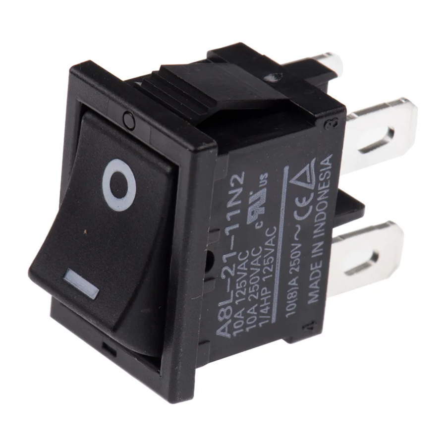
Rocker Switch
Precautions
Do not wire the Switch or touch any terminal of the
Switch while power is being supplied. Or it may
result in electric shock.
To increase the reliability of operation, test the Switch before
actual operation.
Be sure that there is an enough insulation distance between any
Switch terminal and metal part.
Mounting
• Turn OFF the power supply before mounting, removing or
wiring the Switch, or before performing maintenance
inspections. Failure to do so many result in electric shock.
• Easy to mount by snap fitting.
• Do not use panels other than ones with the designated
thickness and dimensions. Remove all burrs from the cutout
before installing the Switch. Otherwise, the Switch may
malfunction.
• Do not impose excessive force on the Switch at the time of
panelmounting. Otherwise the Switch may be damaged or
deformed, and the Switch mechanism may malfunction as a
result.
• When mounting the switch to a panel, apply weight on the case
and flange. Do not apply force to the operation button.
Pushing Position
Wiring
● Type A8L, and A8A Switches
• Use the ON and OFF marks (concave) on the case and flange
as guides for installing direction.
OFF
ON
A8L
• Use wires with sizes suitable for load (current) which is to be
applied.
• Using this product to open/close small-load circuits may cause
negative effects on performance. Perform inspection in the
actual-use condition.
Caution
Case Bezel
φ1.6 concave
ON
OFF
A8A
Safety Precautions
● Type A8L Switch
• When inserting a receptacle to the tab terminal, apply weight
on the case and flange to support.
Without support, a plastic hook of the switch may become
deformed or broken.
• After completing wiring to the switch, secure an appropriate
insulating distance.
• Take care so that no force is regularly applied on the terminal
after wiring.
• Manual soldering must be done within 3 seconds with a 60 W
soldering iron (maximum tip temperature 420°C). Do not apply
force on the terminal.
• If using a solder bath, finish within 5 seconds in the case of
270°C soldering solution, and within 3 seconds in the case of
350°C soldering solution.
• For A8L-@@-@5@@, use only the FASTON receptacle #187
(6.3 × 0.8 mm).
• Soldered terminal (A8L-@@-@1@@) does not satisfy the
certification as a tab terminal according to the IEC standards. If
you need a standard certification, use it as a soldered terminal.
● Type A8A Switch
Use a FASTON receptacle #250 (t = 0.8) to connect lead wire.
Soldering cannot be used for wiring.
● Type A8G Switch
• Wire the contact terminals with #250 receptacles and the coil
terminals with #110 receptacles. Insert the terminals straight
into the receptacles. The insertion force varies with the
receptacle. Test the insertion force of each receptacle under
the actual operating conditions.
• Do not solder the terminals, otherwise the performance of the
terminals may be affected.
• Do not energize coil terminals for more than 10 s, otherwise the
performance of the coil may be affected.
• Each coil terminal has a polarity. When wiring, be sure not to
make any mistake in polarity.
Environment for Storage and Use
• Do not use the Switch in places with sulfide gas, corrosive gas,
sea breeze, oil spray, or direct sunlight. Otherwise, the Switch
may malfunction.
• Do not use the Switch in places that are visibly dusty.
Otherwise, the contacts may fail to operate correctly.
● Type A8L, A8A, and A8G
The switches are not sealed to prevent to enter the dust particles
and liquuid perfectly. Test the Switches under the actual
operating conditions before use.
● A8G
The Switch may malfunction in a strong magnetic field because
the Switch has a permanent magnet and solenoid. Test the
Switch under the actual operating conditions before use.
1
Advertisement

Related Manuals for Omron A8L


Summary of Contents for Omron A8L
- Page 1 • Turn OFF the power supply before mounting, removing or 350°C soldering solution. wiring the Switch, or before performing maintenance • For A8L-@@-@5@@, use only the FASTON receptacle #187 inspections. Failure to do so many result in electric shock. (6.3 × 0.8 mm).
- Page 2 Electronic and Mechanical Components Company Regional Contact Americas Europe https://www.components.omron.com/ http://components.omron.eu/ Asia-Pacific China https://ecb.omron.com.sg/ https://www.ecb.omron.com.cn/ Korea Japan https://www.omron-ecb.co.kr/ https://www.omron.co.jp/ecb/ © OMRON Corporation 2007-2020 All Rights Reserved. Cat. No. A202-E1-04 In the interest of product improvement, specifications are subject to change without notice. 1020(0207)(O)