Table of Contents
Advertisement
Notes: Please use this manual together with service manual
Model No.(SA-MAX4000PN), Order no. (PSG1504011CE).
• CD Mechanism Unit, Order No. PSG1303059AE
• Speaker system SB-MAX4000E (For SA-MAX4000E), Order No: PSG1501010CE
• Speaker system SB-MAX4000GS (For SA-MAX4000GM/GS), Order No: PSG1501010CE
TABLE OF CONTENTS
1 Notes ----------------------------------------------------------------- 3
2 Safety Precautions----------------------------------------------- 4
2.1. Before Repair and Adjustment ------------------------- 4
2.2. Power Supply using SMPS Module------------------- 5
2.3. Safety Parts Information -------------------------------- 5
3 Specifications ----------------------------------------------------- 6
4 Schematic Diagram ---------------------------------------------- 7
Model No.
Product Color: (K)...Black Type
PAGE
4.1. Main (CD Motor Driver) Circuit -------------------------7
4.2. Main (USB EMMC) Circuit -------------------------------8
4.3. Main (SOC IO Expander) Circuit (1/2) ----------------9
4.4. Main (SOC IO Expander) Circuit (2/2) -------------- 10
4.5. Main (Damp) Circuit (1/2) ------------------------------ 11
4.6. Main (Damp) Circuit (2/2) ------------------------------ 12
4.7. Main (Connector) Circuit (1/2) ------------------------ 13
© Panasonic Corporation 2015. All rights reserved.
Unauthorized copying and distribution is a violation of
law.
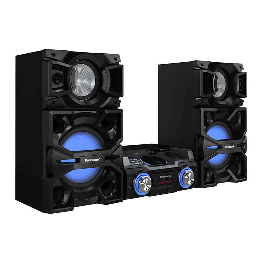
CD Stereo System
SA-MAX4000E
SA-MAX4000GM
SA-MAX4000GS
PSG1505006AE
PAGE
Advertisement
Table of Contents

Related Manuals for Panasonic SA-MAX4000E


Summary of Contents for Panasonic SA-MAX4000E
-
Page 1: Table Of Contents
Notes: Please use this manual together with service manual Model No.(SA-MAX4000PN), Order no. (PSG1504011CE). • CD Mechanism Unit, Order No. PSG1303059AE • Speaker system SB-MAX4000E (For SA-MAX4000E), Order No: PSG1501010CE • Speaker system SB-MAX4000GS (For SA-MAX4000GM/GS), Order No: PSG1501010CE TABLE OF CONTENTS... - Page 2 4.8. Main (Connector) Circuit (2/2) ------------------------ 14 4.9. Main (DSP) Circuit --------------------------------------- 15 4.10. Main (Tuner AUX) Circuit ------------------------------ 16 4.11. Main (Vreg Fan) Circuit (1/3) -------------------------- 17 4.12. Main (Vreg Fan) Circuit (2/3) -------------------------- 18 4.13. Main (Vreg Fan) Circuit (3/3) -------------------------- 19 5 Printed Circuit Board ------------------------------------------ 20 5.1.
-
Page 3: Notes
1 Notes This service manual contains technical information which will allow service personnel’s to understand and service this model. Please place orders using the parts list and not the drawing reference numbers. If the circuit is changed or modified, this information will be followed by supplement service manual to be filed with original service manual. -
Page 4: Safety Precautions
2 Safety Precautions 2.1. Before Repair and Adjustment Disconnect AC power to discharge AC capacitor as indicate below diagram through a 10 Ω, 10 W resistor to ground. Figure 1-2 Caution: DO NOT SHORT-CIRCUIT DIRECTLY (with a screwdriver blade, for instance), as this may destroy solid state devices. After repairs are completed, restore power gradually using a variac, to avoid overcurrent. -
Page 5: Power Supply Using Smps Module
2.2. Power Supply using SMPS Module This model uses Switching Mode Power Supply (SMPS) to provide the power supply to the unit. Here is the supplied part no. for the SMPS Module 1) N0AC2GP00004 Figure 1-3 2.3. Safety Parts Information Safety Parts List: There are special components used in this equipment which are important for safety. -
Page 6: Specifications
Version ® Bluetooth 2.1 + EDR System: SC-MAX4000E Class Class 2 Main Unit: SA-MAX4000E Supported profiles A2DP, AVRCP, SPP, OPP, FTP Speaker System: SB-MAX4000E Operating frequency 2.4 GHz band FH-SS Operation distance 10 m line of sight System: SC-MAX4000GM... -
Page 7: Schematic Diagram
C5020 C5004 10V100 C5003 C5018 DVD-LD 0.01 GND-LD LB5002 D5001 G1C100KA0101 B0JCAE000001 SYS5V_GND SO: MAIN (SOC I/O EXPANDER): SCHEMATIC DIAGRAM - 3 ~ 4 VR: MAIN (VREG FAN): SCHEMATIC DIAGRAM - 11 ~ 13 SA-MAX4000E/GM/GS MAIN (CD MOTOR DRIVER) CIRCUIT... -
Page 8: Main (Usb Emmc) Circuit
SO: MAIN (SOC I/O EXPANDER): SCHEMATIC DIAGRAM - 3 ~ 4 CO: MAIN (CONNECTOR): SCHEMATIC DIAGRAM - 7~ 8 DS: MAIN (DSP): SCHEMATIC DIAGRAM - 9 SA-MAX4000E/GM/GS MAIN (USB EMMC) CIRCUIT VR: MAIN (VREG FAN): SCHEMATIC DIAGRAM - 11 ~ 13... -
Page 9: Main (Soc Io Expander) Circuit (1/2)
CO: MAIN (CONNECTOR): SCHEMATIC DIAGRAM - 7~ 8 R1078) DS: MAIN (DSP): SCHEMATIC DIAGRAM - 9 VR: MAIN (VREG FAN): SCHEMATIC DIAGRAM - 11 ~ 13 SA-MAX4000E/GM/GS MAIN (SOC I/O EXPANDER) CIRCUIT NOTE: “ * ” REF IS FOR INDICATION ONLY... -
Page 10: Main (Soc Io Expander) Circuit (2/2)
DS: MAIN (DSP): SCHEMATIC DIAGRAM - 9 DJ_LED TU: MAIN (TUNER AUX): SCHEMATIC DIAGRAM - 10 VR: MAIN (VREG FAN): SCHEMATIC DIAGRAM - 11 ~ 13 REM_IN REM_IN MPORT_DET MPORT_DET SA-MAX4000E/GM/GS MAIN (SOC I/O EXPANDER) CIRCUIT NOTE: “ * ” REF IS FOR INDICATION ONLY... -
Page 11: Main (Damp) Circuit (1/2)
BST_C R3205 DS: MAIN (DSP): SCHEMATIC DIAGRAM - 9 GVDD_CD BST_D C3206 C3223 VR: MAIN (VREG FAN): SCHEMATIC DIAGRAM - 11 ~ 13 0.033 R3210 R3211 HEATSINK* SA-MAX4000E/GM/GS MAIN (DAMP) CIRCUIT NOTE: “ * ” REF IS FOR INDICATION ONLY... -
Page 12: Main (Damp) Circuit (2/2)
C3000 R3665 16V33 DAMPGND DS: MAIN (DSP): SCHEMATIC DIAGRAM - 9 R3016 R3017 R3018 R3019 VR: MAIN (VREG FAN): SCHEMATIC DIAGRAM - 11 ~ 13 HEATSINK* HEATSINK* SA-MAX4000E/GM/GS MAIN (DAMP) CIRCUIT NOTE: “ * ” REF IS FOR INDICATION ONLY... -
Page 13: Main (Connector) Circuit (1/2)
DS: MAIN (DSP): SCHEMATIC DIAGRAM - 9 R2563 IN SCHEMATIC DGND TU: MAIN (TUNER AUX): SCHEMATIC DIAGRAM - 10 C2553 100P R2564 DIAGRAM - 18 VR: MAIN (VREG FAN): SCHEMATIC DIAGRAM - 11 ~ 13 C2554 100P R2565 SA-MAX4000E/GM/GS MAIN (CONNECTOR) CIRCUIT... -
Page 14: Main (Connector) Circuit (2/2)
US: MAIN (USB EMMC): SCHEMATIC DIAGRAM - 2 LED DRIVE SO: MAIN (SOC I/O EXPANDER): SCHEMATIC DIAGRAM - 3 ~ 4 VR: MAIN (VREG FAN): SCHEMATIC DIAGRAM - 11 ~ 13 QR2512 B1GBCFGN0016 LED DRIVE SA-MAX4000E/GM/GS MAIN (CONNECTOR) CIRCUIT QR2511 B1GBCFGN0016 LED DRIVE... -
Page 15: Main (Dsp) Circuit
SO: MAIN (SOC I/O EXPANDER): SCHEMATIC DIAGRAM - 3 ~ 4 DA: MAIN (DAMP): SCHEMATIC DIAGRAM - 5 ~ 6 CO: MAIN (CONNECTORS): SCHEMATIC DIAGRAM - 7~ 8 TU: MAIN (TUNER AUX): SCHEMATIC DIAGRAM - 10 VR: MAIN (VREG FAN): SCHEMATIC DIAGRAM - 11 ~ 13 SA-MAX4000E/GM/GS MAIN (DSP) CIRCUIT... -
Page 16: Main (Tuner Aux) Circuit
SO: MAIN (SOC I/O EXPANDER): SCHEMATIC DIAGRAM - 3 ~ 4 CO: MAIN (CONNECTOR): SCHEMATIC DIAGRAM - 7~ 8 DS: MAIN (DSP): SCHEMATIC DIAGRAM - 9 VR: MAIN (VREG FAN): SCHEMATIC DIAGRAM - 11 ~ 13 SA-MAX4000E/GM/GS MAIN (TUNER AUX) CIRCUIT... -
Page 17: Main (Vreg Fan) Circuit (1/3)
SO: MAIN (SOC I/O EXPANDER): SCHEMATIC DIAGRAM - 3 ~ 4 PW_1R5V DA: MAIN (DAMP): SCHEMATIC DIAGRAM - 5 ~ 6 CO: MAIN (CONNECTORS): SCHEMATIC DIAGRAM - 7~ 8 DS: MAIN (DSP): SCHEMATIC DIAGRAM - 9 SA-MAX4000E/GM/GS MAIN (VREG FAN) CIRCUIT... -
Page 18: Main (Vreg Fan) Circuit (2/3)
1.8M R2196 R2178 PW_CD_3R3V 270K R2181 Q2116 B1GBCFJJ0041 SWITCH DGND2 R2225 R2199 CDMOTOR_GND CD3R3_GND TO MAIN (VREG FAN) TO MAIN (VREG FAN) CIRCUIT (1/3) CIRCUIT (3/3) DA: MAIN (DAMP): SCHEMATIC DIAGRAM - 5 ~ 6 SA-MAX4000E/GM/GS MAIN (VREG FAN) CIRCUIT... -
Page 19: Main (Vreg Fan) Circuit (3/3)
DA: MAIN (DAMP): SCHEMATIC DIAGRAM - 5 ~ 6 C2195 CO: MAIN (CONNECTORS): SCHEMATIC DIAGRAM - 7 ~ 8 DAMPGND DS: MAIN (DSP): SCHEMATIC DIAGRAM - 9 TU: MAIN (TUNER AUX): SCHEMATIC DIAGRAM - 10 SA-MAX4000E/GM/GS MAIN (VREG FAN) CIRCUIT... -
Page 20: Printed Circuit Board
K3200 Q3501 K3000 K3201 K3001 R2235 Q2117 R2201 LB2105 C3568 C3567 QR2102 R2200 R2205 R6113 R2208 C6109 R6116 C6121 R6114 R6115 C6108 C6120 C2183 R6112 LB2531 LB2532 LB2535 LB2533 LB2534 LB2536 R3661 3765JA 3765JA LB2537 (SIDE A) SA-MAX4000E/GM/GS MAIN P.C.B. -
Page 21: Main P.c.b. (Side B)
11-LL+ VA51 2-RL- 4-RM- 6-RH- 8-LM- 10-LH- 12-LL- R3662 3765JA 3765JA CN2502 CN2501 (TO SB-MAX4000) (TO SB-MAX4000) (SIDE B) TO SPEAKERS AUX IN 1 FM ANT AM ANT NOTE: " * " REF IS FOR INDICATION ONLY SA-MAX4000E/GM/GS MAIN P.C.B. -
Page 22: Exploded View And Replacement Parts List
6 Exploded View and Replacement Parts List 6.1. Cabinet Parts Location 1 DP1700 DP1800 IR1730 (FL DISPLAY P.C.B.) (ILLUMINATION JOG P.C.B.) (USB P.C.B.) P1960 P1700 P1932 CN9002 P1930 VR1960 JK9001 *P7701 CN9001 VR1930 JK9002 (VOLUME JOG P.C.B.) (BT&NFC P.C.B.) 22-1 (MIC P.C.B.) 22-3 CN1401... -
Page 23: Cabinet Parts Location
6.2. Cabinet Parts Location 2 P1650 P1501 P1500 (BUTTON RIGHT P.C.B.) P1502 (BUTTON LEFT P.C.B.) P1503 P1504 P1601 P1600 P1602 VR1600 (MULTI CONTROL P.C.B.) SA-MAX4000EK SA-MAX4000GM/GS CABINET DRAWING NOTE: " * " PART IS NOT SUPPLIED / REF IS FOR INDICATION ONLY. -
Page 24: Cabinet Parts Location
6.3. Cabinet Parts Location 3 54 54 *HEATSINK UNIT (CD MECHANISM UNIT) JK3500 JK6002 JK52 JK51 CN2103 CN2501 ZJ6101 CN2502 CN2105 CN2104 (MAIN P.C.B.) P1002 CN2505 CN2506 CN2509 CN2508 CN2507 CN7002 (CD INTERFACE P.C.B.) ZJ1001 P5101 P5001 CN7001 S7201 (SMPS MODULE) SA-MAX4000EK SA-MAX4000GM/GS NOTE: "... -
Page 25: Packaging
6.4. Packaging SB-MAX4000 ** TOP PAD ACCESSORIES BAG F R O N T SA-MAX4000E/GM/GS AC CORD AC CORD (FOR GM/GS ONLY) AC CORD (FOR GM/GS ONLY) OI BOOK FM INDOOR ANTENNA F R O N T AM LOOP ANTENNA POLYFOAM (BOTTOM LEFT) -
Page 27: Mechanical Replacement Part List
6.5. Mechanical Replacement Part List Safety Ref. Part No. Part Name & Qty Remarks Description REX1747 WIRE (USB- Safety Ref. Part No. Part Name & Qty Remarks MAIN) Description REX1702 13P WIRE (MAIN- SMPS) CABINET RGK2538-1K CD LID CHASSIS RGK2540-1K TOP ORNAMENT RGL0787B-W USB REC LIGHT... - Page 28 Safety Ref. Part No. Part Name & Qty Remarks Description RMB0982 CD LID SPRING RMG1002-D MECHA CUSHION RMGX0033A-K CD LID CUSHION RMK0870A-2 BOTTOM CHASSIS RMQ2273 DJ SLIDER SHEET RMQ2275 FRONT MECHA SUP- PORT RMQ2352 DJ SHEET RMX0510 SMPS PCB SPACER RSC1293-1 MIC SHIELD PLATE RHD26016-1L...
-
Page 29: Electrical Replacement Part List
6.6. Electrical Replacement Part List Safety Ref. No. Parts No. Parts name & Description Remarks SA-MAX4000PN SA-MAX4000E/GM/GS PCB1 RFKV5075RA RFKB5075QA MAIN P.C.B W/DATA (E.S.D), JIGS & ADJ, GM/GS PCB1 RFKV5075RA RFKB5075YA MAIN P.C.B W/DATA (E.S.D), JIGS & ADJ, E PCB3... - Page 30 Safety Ref. No. Parts No. Parts name & Description Remarks SA-MAX4000PN SA-MAX4000E/GM/GS LB5013 D0GBR00J0004 J0JBC0000010 INDUCTOR LB5014 D0GBR00J0004 J0JBC0000010 INDUCTOR LB5015 D0GBR00J0004 J0JBC0000010 INDUCTOR LB5016 D0GBR00J0004 J0JBC0000010 INDUCTOR LB5017 D0GBR00J0004 J0JBC0000010 INDUCTOR LB5018 D0GBR00J0004 J0JBC0000010 INDUCTOR LB1041 ERJ2GEJ472X D0GA222JA023 2.2K...
- Page 31 Safety Ref. No. Parts No. Parts name & Description Remarks SA-MAX4000PN SA-MAX4000E/GM/GS C3013 F1H1H122B047 1200pF C3014 F1H1H122B047 1200pF C3021 F1H1H122B047 1200pF C3022 F1H1H122B047 1200pF C3109 F1H1H122B047 1200pF C3110 F1H1H122B047 1200pF C3120 F1H1H122B047 1200pF C3121 F1H1H122B047 1200pF C3209 F1H1H122B047 1200pF C3210...