Advertisement
Quick Links
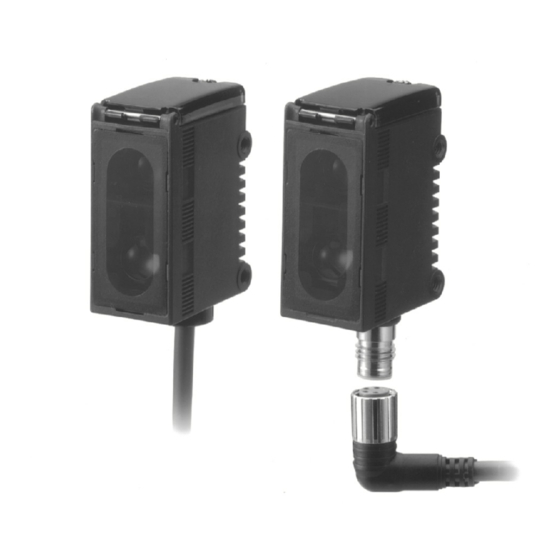
Distance-setting Photoelectric Sensor
Pin-point Beam, Adjustable Focus
Point and Teach Mode for Reliable
Detection
Teach mode speeds accurate setup
H
Smallest pin-point beam in the industry
H
allows detection of minute objects
Optical system achieves stable detection
H
of objects regardless of glossiness,
color, material, surface irregularities, or
inclination
Connector and cabled models
H
Rugged IP67, NEMA 4 enclosure
H
Selectable Light-ON/Dark-ON operation
H
Ordering Information
J SENSORS
Appearance
pp
Supply
pp y
voltage
l
10-30 VDC
J CONNECTOR CORDSETS
Shape
Straight
Straight
Ri ht
Right angle
l
R
Light source
g
Connection
method
h d
Red
Pre-leaded
Connector
Infrared
Pre-leaded
Connector
Description
Four-wire, vibration-proof, single-ended
,
cable
bl
Sensing/Setting range
g/
g
g
5 mm
20 mm
30 mm 50 mm
Min. setting
Setting range:
Max setting
Max. setting
30 to 50 mm
30 to 50 mm
Sensing range:
5 to 50 mm
5 mm
50 mm
30 mm
Min. setting
Setting range:
White paper 50 to 200 mm
Max. setting
Max setting
Sensing range:
White paper 5 to 200 mm
Cable length
p
,
g
2 m (6.56 ft)
5 m (16.40 ft)
2 m (6.56 ft)
5 m (16.40 ft)
2
E3G-L1/L3
Part number
NPN
PNP
E3G-L11
E3G-L12
g
g
E3G-L15
E3G-L16
E3G-L31
E3G-L32
200 mm
E3G-L35
E3G-L36
Part number
XS3F-M421-402-R
XS3F-M421-405-R
XS3F-M422-402-R
XS3F-M422-405-R
Advertisement

Related Manuals for Omron E3G-L1 Series


Summary of Contents for Omron E3G-L1 Series
- Page 1 Distance-setting Photoelectric Sensor E3G-L1/L3 Pin-point Beam, Adjustable Focus Point and Teach Mode for Reliable Detection Teach mode speeds accurate setup Smallest pin-point beam in the industry allows detection of minute objects Optical system achieves stable detection of objects regardless of glossiness, color, material, surface irregularities, or inclination Connector and cabled models...
-
Page 2: Specifications
E3G-L1/L3 E3G-L1/L3 J REPLACEMENT PARTS Mounting brackets Remarks Part number Provided with E3G-Lj1/-Lj2 E39-L139 Provided with E3G-Lj5/-Lj6 E39-L140 Specifications Ratings/Characteristics Sensing method Diffuse Part number NPN output E3G-L11 E3G-L15 E3G-L31 E3G-L35 PNP output E3G-L12 E3G-L16 E3G-L32 E3G-L36 Setting range 30 to 50 mm (1.18 to 1.97 in) 50 to 200 mm (1.97 to 7.87 in) (Kodak white paper, black paper: 50 x 50 mm) (Kodak white paper 50 x 50 mm) -
Page 3: Operation
E3G-L1/L3 E3G-L1/L3 Specifications Table - - continued from previous page Sensing method Diffuse Part number NPN output E3G-L11 E3G-L15 E3G-L31 E3G-L35 PNP output E3G-L12 E3G-L16 E3G-L32 E3G-L36 Connection method Pre-leaded M8 connector Pre-leaded M8 connector (standard length: 2 m) (standard length: 2 m) Weight (packed state) Approx. -
Page 4: Engineering Data
E3G-L1/L3 E3G-L1/L3 Engineering Data J OPERATING RANGE E3G-L1j (in NORMAL Mode) E3G-L1j (in ZONE Mode) Setting distance: 30 mm, Setting distance: 30 mm, 40 mm, 50 mm 40 mm, Target object: White paper 50 "50 mm 50 mm 40 mm 30 mm 50 mm 30 mm... - Page 5 E3G-L1/L3 E3G-L1/L3 J ANGLE CHARACTERISTICS E3G-L1j (Up and Down) E3G-L1j (Left and Right) Target object: White paper 50 " 50 mm Target object: White paper 50 " 50 mm Sensing distance:30 mm Sensing distance:30 mm (Left and Right) (Up and Down) Inclination Inclination angle...
- Page 6 E3G-L1/L3 E3G-L1/L3 J ANGLE CHARACTERISTICS (CONT.) E3G-L3j (Up and Down) E3G-L3j (Left and Right) Target object: White paper 50 " 50 mm Target object: White paper 50 " 50 mm Sensing distance:150 mm Sensing distance:150 mm (Up and Down) (Left and Right) Inclination Inclination angle...
- Page 7 E3G-L1/L3 E3G-L1/L3 J SENSING DISTANCE VS. SENSING OBJECT MATERIAL E3G-L1V (at 30 mm Setting Distance) E3G-L1V (at 40 mm Setting Distance) White Veneer Fiberboard Black Black Mirror White Veneer Fiberboard Black Black Mirror paper paper rubber paper paper rubber Material Material E3G-L1V (at 50 mm Setting Distance) E3G-L3j (at 50 mm Setting Distance)
-
Page 8: Installation
E3G-L1/L3 E3G-L1/L3 Nomenclature UP/DOWN selector Selects the switching Operation mode selector direction at threshold. Selects L-ON or D-ON. NORM L Operation indicator (Orange) NORMAL/ZONE selector ON when output is ON. Selects the detection mode. NEAR ZONE D Distance indicator (Green) TEACH Display the distance relative to the threshold. - Page 9 E3G-L1/L3 E3G-L1/L3 J ADJUSTMENTS If the sensor is not in stable operation due to color differences, make a fine adjustment of the threshold level and confirm that the sensor operates in stable state. Refer to Manual Teaching (Fine Distance Setting. Adjustment Steps Install, wire, and turn on the sensor.
- Page 10 E3G-L1/L3 E3G-L1/L3 J ADJUSTMENTS (CONT.) Normal One-point Teaching E3G-L Sensor Threshold a (La) Background Background Procedure Operation Panel status Set the mode selector to TEACH. NORM L NORM L Set the NORMAL/ZONE mode selector to NORMAL. ZONE D NEAR Press the SET button with the background. The threshold Threshold indicator indicator (red) will turn ON.
- Page 11 E3G-L1/L3 E3G-L1/L3 J ADJUSTMENTS (CONT.) Normal Two-point Teaching Sensor Sensor E3G-L Object Object Threshold a (La) Background Background Background Procedure Operation Panel status Set the mode selector to TEACH. Object NORM L Set the NORMAL/ZONE mode selector to NORMAL. Press the SET button with a sensing object located at sensing NEAR ZONE D Threshold indicator...
- Page 12 E3G-L1/L3 E3G-L1/L3 J ADJUSTMENTS (CONT.) Manual Teaching (Fine Distance Setting) Procedure Operation Panel status Fine adjustment of the threshold is possible after teaching. SET pressed with UP/ NORM L DOWN se- Threshold increases lector set to lector set to NEAR ZONE D Set the mode selector to ADJ.
- Page 13 E3G-L1/L3 E3G-L1/L3 Dimensions Unit: mm (inch) J SENSORS Preleaded Models E3G-L11/L31 Shown with mounting bracket E39-L139 (included) E3G-L12/L32 Mounting holes Mounting bracket can Two, M4 be attached to this side. Distance indicator Threshold (green) indicator (red) Operation indicator Two, R2.2 18.4 (orange) 25.4...
- Page 14 E3G-L1/L3 E3G-L1/L3 Connector Models E3G-L15/L35 Shown with mounting bracket E39-L140 (included) E3G-L16/L36 Mounting holes Mounting bracket can Two, M4 be attached to here. Distance indicator (green) Threshold indicator 25.4 (red) Two, R2.2 Operation indicator (1.00) (orange) 18.4 (0.72) Two, M3 Two, 8-dia.
- Page 15 E3G-L1/L3 E3G-L1/L3 J MOUNTING BRACKETS E39-L139 E39-L140 Material: Stainless steel (SUS304) Material: Stainless steel (SUS304) Note: Provided with E3G-Lj1/-Lj2 Note: Provided with E3G-Lj5/-Lj6 J CONNECTOR CORDSETS Straight XS3F-M421-402-R (L = 2 m) XS3F-M421-405-R (L = 5 m) 4 dia. Right Angle XS3F-M422-402-R (L = 2 m) XS3F-M422-405-R (L = 5 m)
- Page 16 E3G-L1/L3 E3G-L1/L3 Precautions Short- -circuit Protection J DESIGNING If the load short- -circuits, the output will be turned off. Disconnect High-voltage Lines power and check the wiring. After correcting the shorted condition, turn power back on. The sensor will reset the Do not place sensor power supply or signal lines within the same short-circuit protection function.
- Page 17 E3G-L1/L3 E3G-L1/L3 NOTE: DIMENSIONS SHOWN ARE IN MILLIMETERS. To convert millimeters to inches divide by 25.4. OMRON ON- -LINE OMRON ELECTRONICS LLC OMRON CANADA, INC. One East Commerce Drive 885 Milner Avenue Global -- http://www.omron.com Schaumburg, IL 60173 Scarborough, Ontario M1B 5V8 USA -- http://www.omron.com/oei...