Table of Contents
Advertisement
Quick Links
Advertisement
Chapters
Table of Contents

Related Manuals for GRASS VALLEY ATP-2000


Summary of Contents for GRASS VALLEY ATP-2000
- Page 1 ATP-2000 ADVANCED TOUCH PANEL User Guide 13-03082-230 AA 24 November 2020...
-
Page 2: Fcc Compliance
Valley USA, LLC, or one of its affiliates or subsidiaries. All other intellectual property rights are owned by GVBB Holdings SARL, Grass Valley USA, LLC, or one of its affiliates or subsidiaries. All third party intellectual property rights (including logos or icons) remain the property of their respective owners. -
Page 3: This Document
Related Documentation Use the following related documentation to configure and use an ATP-2000 Advanced Touch Panel. You can obtain the latest product documentation from Grass Valley’s website, see the ‘Documentation Library’ at https://wwwapps.grassvalley.com/docs/page/... - Page 4 Notices...
-
Page 5: Important Safety Information
The presence of this symbol in or on Grass Valley equipment means that it has been tested and certified as complying with applicable Underwriters Laboratory (UL) regulations and recommendations for USA. - Page 6 Notices The presence of this symbol in or on Grass Valley equipment means that it has been tested and certified as complying with applicable Intertek Testing Services regulations and recommendations for USA/Canada. The presence of this symbol in or on Grass Valley product means that it complies with all applicable European Union (CE) directives.
- Page 7 ATP-2000 User Guide Cautions A caution indicates a possible hazard to equipment that could result in equipment damage. Observe the following cautions when operating or working on this equipment: • This equipment is meant to be installed in a restricted access location.
- Page 8 Replace the battery only with the same or equivalent type recommended by the manufacturer. Dispose of used batteries according to the manufacturer’s instructions. Before disposing of your Grass Valley equipment, please review the Disposal and Recycling Information at: http://www.grassvalley.com/assets/media/5692/Take-Back_Instructions.pdf...
- Page 9 ATP-2000 User Guide Mesures de sécurité et avis importants La présente section fournit des consignes de sécurité importantes pour les opérateurs et le personnel de service. Des avertissements ou mises en garde spécifiques figurent dans le manuel, dans les sections où ils s’appliquent. Prenez le temps de bien lire les consignes et assurez-vous de les respecter, en particulier celles qui sont destinées à...
- Page 10 électrique, de compatibilité électromagnétique et de conformité environnementale. Le symbole ci-contre sur un appareil Grass Valley ou à l’intérieur de l’appareil indique qu’il est conforme aux normes applicables en matière de sécurité laser. Avertissements Les avertissements signalent des conditions ou des pratiques susceptibles d’occasionner des blessures graves, voire fatales.
- Page 11 ATP-2000 User Guide • Ne pas utiliser cet appareil dans une atmosphère explosive. • Présence possible de courants de fuite. Un raccordement à la masse est indispensable avant la mise sous tension. • Après tout travail d’entretien ou de réparation, faites effectuer des contrôles de sécurité...
- Page 12 Remplacez la pile uniquement par un modèle identique ou équivalent recommandé par le fabricant. Disposez des piles usagées conformément aux instructions du fabricant. Avant de vous séparer de votre équipement Grass Valley, veuillez consulter les informations de mise au rebut et de recyclage à: http://www.grassvalley.com/assets/media/5692/Take-Back_Instructions.pdf...
- Page 13 Grass Valley believes this environmental information to be correct but cannot guarantee its completeness or accuracy since it is based on data received from sources outside our company. All specifications are subject to change without notice.
-
Page 14: Further Safety Information
Lithium Batteries Battery Warning Your Grass Valley equipment usually comes with at least one button cell (coin cell) battery located on the main printed circuit board. The batteries are used for settings backup and should not need to be replaced during the lifetime of the equipment. - Page 15 • Aromatic Solvents. Mains Supply Voltage Before connecting the ATP-2000 unit to a mains electricity supply with the Power Supply Unit, observe the safety warnings section and ensure that the local mains supply is within the rating stated on the rear of the Power Supply Unit.
-
Page 16: Safety And Emc Standards
ATP-2000 User Guide Safety and EMC Standards This equipment complies with the following standards: Safety Standards IEC 62368-1 : 2014 (Second Edition) Audio/video information and communication technology low voltage equipment. EN 62368-1 : 2014+A11:2017 (Second Edition) Audio/video information and communication technology low voltage equipment. - Page 17 EMC Performance of Cables and Connectors Grass Valley products are designed to meet or exceed the requirements of the appropriate European EMC standards. In order to achieve this performance in real installations it is essential to use cables and connectors with good EMC characteristics.
-
Page 18: Table Of Contents
Initial ATP-2000 Panel Device Configuration ........ - Page 19 ATP-2000 Control Screen (Web Page)........
- Page 20 Preliminaries ..............62 Step 1: Uninstall ATP-2000 Panel Unit from Rack ......63 Step 2: Panel Unit Disassembly .
- Page 21 Table of Contents...
-
Page 22: Introduction
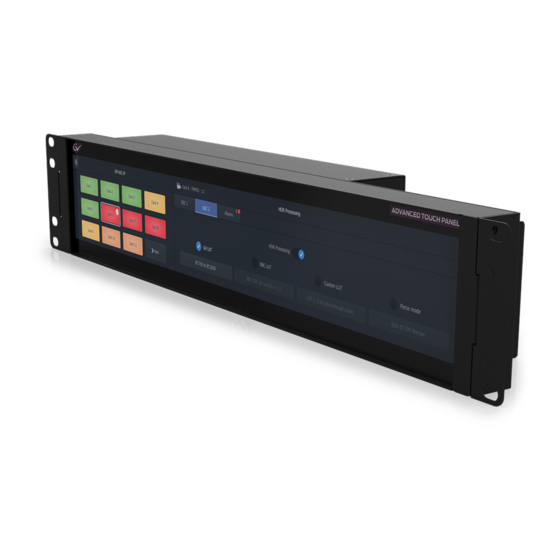
• High quality touch screen and symmetrical viewing angle. • Flexible and optimized soft user control panels. • Device parameter control. • Fail-safe file system. An ATP-2000 initially powers up and discovers devices of a Grass Valley GV Orbit system. Soft panels are available for supported devices. -
Page 23: Order Codes
The panel is designed to work with a GV Orbit system and requires the system to have its DHCP facility enabled when configured. Supported Devices The ATP-2000 Advanced Touch Panel supports the ability to configure, control, and monitor parameters on IQ and Densité devices. Table 1-3: ATP-2000 - Supported Devices Card... -
Page 24: This Document
ATP-2000 User Guide This Document This document presents the ATP-2000 product, how to get started with it and how to operate it. See: • Chapter 2, Panel Installation, on page 5, for rack installation instructions • Chapter 3, Getting Started, on page 13, for instructions on getting started with an ATP- 2000 in a GV Orbit system. - Page 25 Introduction This Document...
-
Page 26: Panel Installation
Panel Installation Panel Installation Unpacking ................6 Rack Mount Installation . -
Page 27: Unpacking
• AC power cords (1x US, 1x GB, 1x Eu); and • 1x 5m Ethernet cable. • 1x ATP-2000 Welcome Note. If there is anything incorrect, then notify your Grass Valley Partner, or Grass Valley, at once. (See Grass Valley Technical Support, on page 69.) -
Page 28: Rack Mount Installation
User Guide Rack Mount Installation The ATP-2000 can be mounted into a 19 inch rack. It requires 2RU of vertical space in a desk- mount or full-rack system: 1 Select an equipment rack location with a nearby AC power socket. -
Page 29: Vesa Mount Installation
Air Venting Grilles Fig. 2-3: ATP-2000 Unit Rear View 4 Secure the ATP-2000 unit to the Vesa mounting bracket with four M4 x 10 mm screws and washers. Fasten it to captive nuts of the rack frame mounting strip. Note: See Environmental, on page 49 in Appendix A, for information about... -
Page 30: Connections
1 Connect an Ethernet network cable to “LAN” with a DHCP service enabled. (See Figure 2-4b.) Note: The ATP-2000 unit needs to be connected to the same ‘control/management’ network as the GV Orbit server(s). 2 Connect the DC power lead from the power supply unit to “DC 12 V”. (See Figure 2-4c.) “DC 12V”... - Page 31 Panel Installation Connections The ATP-2000 unit powers on automatically; there is no power on/off switch. CAUTION An ATP-2000 Advanced Touch Panel contains two micro SD memory cards. These are fitted to two micro SD card slots in the unit and should not be removed.
-
Page 32: Starting Up
Splash Screen c) Home Screen Fig. 2-6: ATP-2000 Start-Up Screens: a) Initial Screen; b) Splash Screen; c) Home Screen. When the ATP-2000 Advanced Touch Panel is showing its Home Screen in the rack, then its rack installation is complete. (See Start-Up Sequence, on page 14, for more information about the device’s start up sequence.) -
Page 33: Powering Off
Panel Installation Powering Off Powering Off To power off the ATP-2000 unit, turn off the DC power that enters the unit from the side. No shutdown procedure is required because the hardware and file system is fail-safe. -
Page 34: Getting Started
Initial ATP-2000 Panel Device Configuration ........ -
Page 35: Start-Up Sequence
Subnet Mask Fig. 3-1: ATP-2000 Splash Screen Home Screen After start-up, the ATP-2000 shows an operating Home screen. See Figure 3-2 for an example home screen. Note: The operating Home screen shown depends on the soft panel currently loaded into the ATP-2000 Advanced Touch Panel. - Page 36 User Guide Click the Home icon to return to the Home screen. Select icon to see panel information. Fig. 3-2: Example ATP-2000 Home Screen (Software version 1.0) Note: Screen brightness is controlled from the unit’s control screen (web page). See Accessing the ATP-2000 Control Screen.
-
Page 37: Initial Atp-2000 Panel Device Configuration
14.) IP Address Assignment The ATP-2000 panel ships with DHCP enabled in its network settings. If a static IP address is required, then this can be set up from the unit’s control screen (web page) along with other network interface settings. -
Page 38: Accessing The Atp-2000 Control Screen
ATP-2000 User Guide In this way, the ATP-2000 automatically joins the GV Orbit system and is seen by all GV Orbit Clients and appears as a device in a GV Orbit Client’s Network window. Accessing the ATP-2000 Control Screen From GV Orbit Client... -
Page 39: Configure Initial Settings In The Control Screen
• GV Server IP - IP address of the GV Orbit server in the system. • Panel Id - ‘Panel Id’ for the ATP-2000 unit in the GV Orbit system. This is a RollCall address (for example E000:01:00) which must be unique in a system. -
Page 40: Step 3: Panel Manager Settings
The GV Orbit system will discover it. This has now set up the minimum settings to get started with the panel. For details about the unit’s web page and other settings, see ATP-2000 Control Screen (Web Page), on page 21. - Page 41 Getting Started Configure Initial Settings in the Control Screen...
-
Page 42: Atp-2000 Control Screen (Web Page)
ATP-2000 Control Screen (Web Page) ........ -
Page 43: Introduction
ATP-2000 Control Screen (Web Page) Introduction Introduction The ATP-2000 unit’s control screen is its web page. This can be accessed using a web browser (for example, Chrome), or the control screen can be accessed from the GV Orbit Client tool. -
Page 44: Atp-2000 Control Screen (Web Page)
User Guide ATP-2000 Control Screen (Web Page) Fig. 4-2: ATP-2000 Web Page Note: The ATP-2000 web page is wide. View the web page in a browser window or a GV Orbit Client window which is at least 1920 pixels wide. - Page 45 Click to apply any Network Settings changes. Server Settings: GVOP Domain Displays the GV Orbit Protocol Domain number assigned to the ATP-2000 panel. This is automatically discovered and assigned to the panel. The Domain number can be entered here if required. Default domain is100.
- Page 46 ‘unfound’ cards from the card list. Logging: Download Log Files Click to download ATP-2000 panel’s log files to the client computer. A zip file is downloaded to the client computer running the web browser. The zip file contains a flat list of one or more ‘log.txt’...
- Page 47 ATP-2000 Control Screen (Web Page) ATP-2000 Control Screen (Web Page)
-
Page 48: Operation
ATP-2000 Home Screen ........ -
Page 49: Start Up Splash Screen
Screen, on page 28, for more information. When the device has started up, the ATP-2000 panel shows a Home screen. See Figure 5-1. ATP-2000 Home Screen The Home screen allows a user to browse GV Orbit system cards and to control card parameters. - Page 50 Note: Items on screen may be grayed out if there are no cards/devices present of that type in the system, or if they are not supported by the ATP-2000 panel. 3 Select a card to control on the LHS. Parameter controls are available on the RHS. See Figure 5-3.
-
Page 51: Card Screens
Device-specific information is not covered in this document. Accessing a Parameter Control Screen At the ATP-2000 Home screen: 1 On the LHS, select the function to control. (For example, select ‘Cards’ .) 2 On the RHS, select the card type to control. (For example, select ‘XIP’ .) 3 On the LHS, select the particular card to control. -
Page 52: Card List Grid
ATP-2000 User Guide Card List Grid All cards of the selected type that can be parameter-controlled are listed on the left-hand side of the panel in a Card List. Depending on the number of card items needing to be listed, the full list of cards may need to be navigated with ‘Next’... -
Page 53: Generic Parameter Control Screen
This section describes parameter change operations that can be done using a soft panel on the ATP-2000 Advanced Touch Panel. These are generic actions and are not specific to any card/device. For parameter controls for specific cards, see the corresponding card documentation. -
Page 54: Change Card Being Controlled
ATP-2000 User Guide Indicates item is selected. Fig. 5-7: Example HDR Processing Parameter Controls (Example shown is for XIP Card) 3 Some card parameter control screens are further broken down into sub-screens which are selectable with further navigation controls. This is shown for the XIP card example in Figure 5-8.... -
Page 55: Back To 'Home' Card Or Card-Channel Main Screen
Operation Generic Parameter Control Screen Back to ‘Home’ Card or Card-Channel Main Screen 1 Click Main Menu to go back to the ‘Home’ card or card-channel Parameter Control screen. Fig. 5-9: Click Main Menu - Example shown is for XIP Card... -
Page 56: Maintenance
Monitoring ATP-2000 Panel Alarms ........ -
Page 57: Re-Boot Panel
Maintenance Re-Boot Panel Re-Boot Panel To restart/reboot the ATP-2000, on the web page. Under the Panel Manager section of the web page: 1 At ‘Reboot Panel’ , click Start. See Figure 6-2. 2 Click OK to any prompts to restart the panel. -
Page 58: Panel System Information
ATP-2000 User Guide Panel System Information System information about a ATP-2000 device can be viewed from GV Orbit Client: • Panel Information from Home Screen • Panel Information in Client Details Dialog • Panel Information on Web Page Panel Information from Home Screen... -
Page 59: Panel Information In Client Details Dialog
Panel Information in Client Details Dialog In the Network window in an open project in GV Orbit Client: 1 Locate the ATP-2000 device in the tree-list, right-click on it and select ‘Info’ . A Details window is shown for the device, displaying device information. -
Page 60: Panel Information On Web Page
Panel Information on Web Page In the Network window in an open project in GV Orbit Client: 1 Locate the ATP-2000 device in the Network window’s tree-list, right-click on it and select ‘Control’ . The ATP-2000’s web page is shown in GV Orbit Client. ... -
Page 61: Software Upgrade
Software Upgrade Software Upgrade Introduction The ATP-2000 Advanced Touch Panel unit is software-upgraded via the GV Orbit Client tool. To upgrade a device with GV Orbit Client, the Network window must be open and showing the ATP-2000 device to be upgraded. -
Page 62: Step 2: Import Upgrade Package
ATP-2000 User Guide Device’s software version Fig. 6-6: ATP-2000 Unit Information in Details Window 3 Close the Details window. Step 2: Import Upgrade Package 1 Right-click on the Network tree-view device item and select ‘Upgrade’ . The Orbit Upgrade window is shown. Any software upgrade packages that might have been previously uploaded are shown listed on the left-hand side, under ‘Available... -
Page 63: Step 3: Upgrade The Atp-2000
Step 4: Finally, Check the Upgraded Software Version 1 Right-click on the Network window upgraded-device item and select ‘Info’ . A Details window is shown displaying unit information. 2 Check that the ATP-2000’s current (upgraded) version of software/firmware is correct. -
Page 64: Monitoring Atp-2000 Panel Alarms
ATP-2000 User Guide Monitoring ATP-2000 Panel Alarms The ATP-2000 issues information about its health and status which conforms to the GV Orchestration Protocol (GVOP). These alarms may be viewed in GV Orbit Client in a GV Orbit system. Note: In order for the panel’s alarms etc. to be visible to GV Orbit Client, the... - Page 65 Maintenance Monitoring ATP-2000 Panel Alarms Table 6-1: ATP-2000 Alarms Item Description DISK_USAGE The remaining disk space. Unit type Id in the RollCall database. IDNAME Unit type name in the RollCall database. IPADDRESS IP address of the panel. IPNAME Host name.
-
Page 66: Getting Panel Log Files
1 Open the ‘Control Screen’ of the ATP-2000 panel (web page). 2 Click Download Log Files. The ATP-2000 panel’s log files are downloaded to the client computer. A single zip file is downloaded which contains one or more ‘log.txt’ files. - Page 67 Maintenance Replacing the Battery...
-
Page 68: Appendix A Hardware Specification
External Connectors ..............51 This appendix provides specification details of the ATP-2000, including: details of the physical characteristics of the panel;... -
Page 69: Unit Views
Hardware Specification Unit Views Unit Views Left-hand side Front Right-hand side GV label Rear Connectors: “LAN” “DC 12V” Right-hand side view and rear top. Left-hand side view. Fig. A-1: ATP-2000 Advanced Touch Panel Unit Views... -
Page 70: Unit Specification
ATP-2000 User Guide Unit Specification Physical Physical Rack mounting 19 inch rack Rack mounting height Dimensions (W x H x D) 483 x 87.6 x 68.8 mm Unit Dimensions, on page 53 for a unit dimensions drawing. Weight 2 kg... -
Page 71: Display Specification
Touchscreen Type PCAP Multi-touch 10 touch points Surface Anti-glare Operating System Information about the embedded operating system on the ATP-2000 Advanced Touch Panel: Quad-core ARM® Cortex Processor Embedded Linux. Type Storage 2x micro SD cards: • 1x 16GB - OS and panel application. -
Page 72: Defaults
ATP-2000 User Guide Note: There is no unit shutdown procedure for powering down the unit; the file system used is fail-safe. Defaults Default IP Settings The control panels are supplied with factory Ethernet interface IP default settings with DHCP enabled. - Page 73 Hardware Specification External Connectors...
-
Page 74: Appendix B Unit Dimensions
Unit Dimensions Top view Left-hand side view Front view Right-hand side view Underside view Rear view Fig. B-1: ATP-2000 Product Dimensions (mm) - Page 75 Unit Dimensions...
-
Page 76: Appendix C Connectors, Controls, Interfaces
Unit On/Off There is no power on/off switch on the unit. The ATP-2000 Advanced Touch Panel unit turns on when power is applied. There is no shutdown procedure for powering down and the file system is fail- safe. -
Page 77: Ethernet Connector
Connectors, Controls, Interfaces Ethernet Connector Ethernet Connector One RJ45 Ethernet network connector (“LAN”) on right-hand side of the unit (as viewed from the front of the unit). This provides: • A 1G/100M/10M Ethernet interface. • Auto-negotiation of connection speed. • Automatic cross-over. LED 2 (Orange/Green) LED 1 (Orange) Fig. -
Page 78: Micro Sd Card Slots
ATP-2000 User Guide Micro SD Card Slots A dual micro SD card slot is located on the top of the unit on one side. Two micro SD cards are fitted to the unit in the factory and are used by the unit for storage of its operating system, application and data. -
Page 79: Not Used' Connectors
Connectors, Controls, Interfaces ‘Not Used’ Connectors ‘Not Used’ Connectors Other connectors on the rear of ATP-2000 are reserved and are not used. This includes: • On the right-hand side of unit (as viewed from the front of the unit), the following connectors are reserved and not used: •... -
Page 80: Appendix D Power Supply Unit
Power Supply Unit Power Supply Unit DC Power Supply Module ............. 60 Physical . -
Page 81: Dc Power Supply Module
Power Supply Unit DC Power Supply Module DC Power Supply Module An ATP-2000 Advanced Touch Panel ships with a DC Power Supply Unit which is also available as a field replaceable unit: ATP-PS01 ATP-2000 power supply. (AC mains to DC power supply unit.) -
Page 82: Appendix E Battery Replacement
Step 1: Uninstall ATP-2000 Panel Unit from Rack ....... . . -
Page 83: Battery Removal Procedure
• Double-sided adhesive tape. Removal Procedure Steps The battery replacement procedure is described below and assumes that the unit is rack- mounted: • Step 1: Uninstall ATP-2000 Panel Unit from Rack • Step 2: Panel Unit Disassembly • Step 3: Remove Battery Unit •... -
Page 84: Step 1: Uninstall Atp-2000 Panel Unit From Rack
ATP-2000 User Guide Step 1: Uninstall ATP-2000 Panel Unit from Rack 1 Turn off the AC power to the ATP-2000 panel’s power supply unit. 2 Disconnect the DC power lead to the ATP-2000 panel unit. (See DC Power Connector, on page 55, for connector location.) 3 Remove the panel unit from the rack. - Page 85 Battery Replacement Step 2: Panel Unit Disassembly Step 2.2: Unit Disassembly 1 Place the unit display-side-down on a soft protecting cloth. The unit’s metal rear cover is facing you. 2 Locate the four rear cover retaining screws. (See Figure E-2.) Rear cover Rear cover Rear cover...
-
Page 86: Step 3: Remove Battery Unit
ATP-2000 User Guide Wire Battery unit, blue casing Fig. E-3: Rear Cover Removed Now proceed to Step 3: Remove Battery Unit. Step 3: Remove Battery Unit 1 Locate the battery unit in the unit. It is a blue casing with a pair of wires (twisted black/ red) going to it from a white, 2-pin header-style connector. -
Page 87: Step 4: Refit Battery Unit
Battery Replacement Step 4: Refit Battery Unit 3 The battery unit’s blue casing is held down with double-sided adhesive tape. Slowly and gently peel the battery unit away from the panel unit. Gently peel away blue casing from This has removed the battery unit. unit Now proceed to Step 4: Refit Battery... -
Page 88: Step 6: Re-Install In Rack
ATP-2000 User Guide Step 6: Re-Install in Rack 1 Install the panel into the rack. 2 Apply DC power and check the panel unit is functioning. This has replace the battery unit in the ATP-2000 panel unit. Done. - Page 89 Battery Replacement Step 6: Re-Install in Rack...
-
Page 90: Contact Us
1-800-547-8949 (US and Canada) or +1 530 478 4148. To obtain a local phone number for the support center nearest you, please consult the Contact Us section of Grass Valley’s website ( www.grassvalley.com An on-line form for e-mail contact is also available from the website.