
Related Manuals for Trane Tracer CH535


Summary of Contents for Trane Tracer CH535
- Page 1 Tracer CH535 Chiller Controller on models CGAX/CXAX July 2020 CG-SVU007D-GB Confi dential and proprietary Trane information Original instructions...
-
Page 2: Table Of Contents
Tracer CH535 Extention Hardware ..............7 Water flow - lift height (l/h - mm) 24 - 500 Not available for FWD30 and FWD45 Tracer CH535 module connections Terminals ..........8 Sound level (L/M/H speed) Sound pressure level (5) (dB(A)) 36/40/43... -
Page 3: General Information
FWD 10 even merely suspected, notify the carrier within 24 hours by registered letter. Notify the local Trane Sales office at the same time. The unit should be totally inspected within 3 days of delivery. If damage is observed, notify the last carrier FWD 12 by registered letter and notify the local sales office. -
Page 4: Fan Motor General Information
Tracer CH535 Presentation Technical Data Important note: This document describes all the functions available on TRACER CH535 with software version 1.x and explains how to program it. Certain parameters must only be modified by qualified personnel. Before changing any parameter, always check that the change does not affect the good and safe operation of the equipment. -
Page 5: Micro Switches
• HW driver: asynchronous half duplex RS485 Master or Slave FWD 12 (see par. 3.2) Serial FOUR Field Bus 2 / J26 • J26: optically isolated/not optically isolated FWD 14 • 3-pin plug-in connector − For Tracer CH535 ext connections FWD 20 CG-SVU007D-GB UNT-PRC002-GB 5 1 1... -
Page 6: Heating Capacity On Water (2) (Kw)
Tracer CH535 Hardware Technical Data Built-In driver module connections terminals Figure 2 – Built-in driver terminal locations Power supply (V/Ph/Hz) 230/1/50 Capacities Cooling capacity on water (1) (kW) 18,8 30,1 Heating capacity on water (2) (kW) 11,9 18,9 20,9 38,2... -
Page 7: Tracer Ch535 Extention Hardware
Tracer CH535 Extention Hardware Figure 3 – CH535 extention terminal locations Sound power levels Discharge Measurement conditions: Measurements taken in a room adjacent to the room containing the FWD, at the outlet of the rectangular duct (1.5 m long) fixed to its discharge opening. -
Page 8: (Type) Centrifugal
Tracer CH535 module connections Terminals Technical Data TRACER CH535 offers customer the possibility to use inputs or outputs in order to: • use an external water setpoint reset using an analog input (option), • use an auxiliary setpoint (option), • connect a remote on/off of the circuit/unit (standard), •... -
Page 9: Alarms Display And Resetting
Alarms Alarms display and resetting A fault on a unit will be shown through the user interface or through 2 digital outputs, one for each refrigerant circuit. The alarms are divided into 3 categories: Warning: Shows that something is wrong on the unit but unit can be kept in operation. A message is displayed on Sound power levels the user interface screen. -
Page 10: Shipped Unit Dimensions
Alarms Technical Data Table 4 – Status, Warning and Alarm messages Reset N° Message Unit Status Description Type No Alarm Unit On See unit status on Main display Power supply (V/Ph/Hz) 230/1/50 Alarm Water Pump1 Manual Unit On Defective water pump 1 Capacities Alarm Water Pump2 Manual... - Page 11 Alarms Reset N° Message Unit Status Description Type Ckt2 Defrost Unit On Defrost on Circuit 2 Loss of water flow for more than 1 sec. Pump Sound power levels Alarm Loss of Water Flow Auto Unit Off restarts by a manual unit mode changeover Faulty sensor, out of range -30..+80°C Discharge Alarm Air Sensor...
- Page 12 Alarms Technical Data Reset N° Message Unit Status Description Type Warning Comp.1A Manual Unit On Maintenance Warning Comp.1B Power supply (V/Ph/Hz) 230/1/50 Manual Unit On Capacities Maintenance Cooling capacity on water (1) (kW) 18,8 30,1 Compressor running hours above the threshold Warning Comp.1C Heating capacity on water (2) (kW)
- Page 13 Alarms Reset N° Message Unit Status Description Type Alarms pCOe 5 IO Auto Unit On pCOextension5 is in default on Analog input #4 mismatch Sound power levels Alarm Drive Fault Manual Unit Off Variable Primary Flow Drive fault Alarm Low Differential Low Differential Pressure on circuit 1 (High Discharge Auto...
-
Page 14: User Interface Display
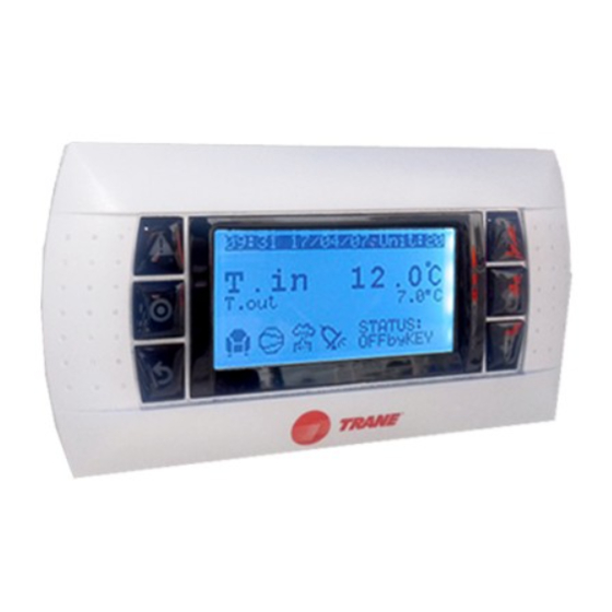
User interface display Technical Data Figure 4 – LCD Display Power supply (V/Ph/Hz) 230/1/50 Capacities Cooling capacity on water (1) (kW) 18,8 30,1 Heating capacity on water (2) (kW) 11,9 18,9 20,9 38,2 Fan motor (type) 2 x direct drive centrifugal Fan power input (3) (kW) 0,23... - Page 15 User interface display Figure 5 – Deluxe touchscreen display Sound power levels Discharge Measurement conditions: Measurements taken in a room adjacent to the room containing the FWD, at the outlet of the rectangular duct (1.5 m long) fixed to its discharge opening. Power level in dB(A), per Hz frequency band Overall power Unit...
-
Page 16: Access To Sub-Menus
30,1 Unit configuration sub-menu Heating capacity on water (2) (kW) 11,9 18,9 20,9 38,2 (accessible to Trane technicians only, not accessible to end users) Fan motor (type) 2 x direct drive centrifugal Fan power input (3) (kW) 0,23 0,46 0,65... -
Page 17: Configuration Menu
(from 9:00 to 15:00). Occupied zone from 6:00 to 21:00. FWD 10 Configuration menu FWD 12 Shows and allows modification of unit configuration with 2 user levels (Local technician and Trane service technician): FWD 14 Local technician (by default password = 0005) allows to:... -
Page 18: Notes
Notes Technical Data Power supply (V/Ph/Hz) 230/1/50 Capacities Cooling capacity on water (1) (kW) 18,8 30,1 Heating capacity on water (2) (kW) 11,9 18,9 20,9 38,2 Fan motor (type) 2 x direct drive centrifugal Fan power input (3) (kW) 0,23 0,46 0,65 1,04... - Page 19 Notes Sound power levels Discharge Measurement conditions: Measurements taken in a room adjacent to the room containing the FWD, at the outlet of the rectangular duct (1.5 m long) fixed to its discharge opening. Power level in dB(A), per Hz frequency band Overall power Unit speed...
- Page 20 For more information, please visit trane.com or tranetechnologies.com. Trane has a policy of continuous product and product data improvement and reserves the right to change design and specifications without notice. We are committed to using environmentally conscious print practices.