
Related Manuals for Trane Tracer CH535


Summary of Contents for Trane Tracer CH535
- Page 1 User Guide Tracer CH535 Chiller Controller on models CGAX/CXAX CG-SVU007C-GB Original instructions...
-
Page 2: Tracer Ch535 Hardware ..................................................................................... 7 Capacities
Tracer CH535 Extention Hardware ..............8 Fan power input (3) (kW) 0,23 0,46 0,65 1,04 1,51 Current amps (3) Start-up amps 14,1 16,5 Air flow Tracer CH535 module connections Terminals ..........9 minimum 1400 1800 2700 nominal 1650 2300 3000 4500 maximum 1970 2600... -
Page 3: Sound Power Levels
Sound power levels Discharge Measurement conditions: Measurements taken in a room adjacent to the room containing the FWD, at the outlet of the rectangular duct (1.5 m long) fixed to its discharge opening. Power level in dB(A), per Hz frequency band Overall power Unit speed... -
Page 4: General Information
Heating capacity (kW) even merely suspected, notify the carrier within 24 hours by registered letter. Notify the local Trane Sales office at the Hot water coil (accessory for blower only) same time. The unit should be totally inspected within 3 days of delivery. If damage is observed, notify the last carrier... -
Page 5: Module Description
Tracer CH535 Presentation Important note: This document describes all the functions available on TRACER CH535 with software version 1.x and explains how to program it. Certain parameters must only be modified by qualified personnel. Before changing any parameter, always Sound power levels check that the change does not affect the good and safe operation of the equipment. -
Page 6: Micro Switches
• Built into main board • HW driver: asynchronous half duplex RS485 Master or Slave (see par. 3.2) Serial FOUR Field Bus 2 / J26 • J26: optically isolated/not optically isolated • 3-pin plug-in connector − For Tracer CH535 ext connections CG-SVU007C-GB UNT-PRC002-GB... - Page 7 Tracer CH535 Hardware Built-In driver module connections terminals Figure 2 – Built-in driver terminal locations Sound power levels Discharge J11 pLAN Measurement conditions: J25 BMS2 J26 FBus2 Measurements taken in a room adjacent to the room containing the FWD, at the outlet of the rectangular duct (1.5 m long) fixed to its discharge opening.
- Page 8 Tracer CH535 Extention Hardware Technical Data Figure 3 – CH535 extention terminal locations Power supply (V/Ph/Hz) 230/1/50 Capacities Cooling capacity on water (1) (kW) 18,8 30,1 Heating capacity on water (2) (kW) 11,9 18,9 20,9 38,2 Fan motor (type) 2 x direct drive centrifugal...
- Page 9 Tracer CH535 module connections Terminals TRACER CH535 offers customer the possibility to use Table 3 – External demand limit setpoint allowances inputs or outputs in order to: Nb of CMP allowed • use an external water setpoint reset using an analog...
- Page 10 Alarms Technical Data Alarms display and resetting A fault on a unit will be shown through the user interface or through 2 digital outputs, one for each refrigerant circuit. The alarms are divided into 3 categories: Warning: Shows that something is wrong on the unit but Power supply (V/Ph/Hz) 230/1/50...
- Page 11 Alarms Table 4 - Status, Warning and Alarm messages Reset N° Message Unit Status Description Type No Alarm Unit On See unit status on Main display Sound power levels Alarm Water Pump1 Manual Unit On Defective water pump 1 Alarm Water Pump2 Manual Unit On Defective water pump 2...
- Page 12 Alarms Technical Data Reset N° Message Unit Status Description Type Ckt2 Defrost Unit On Defrost on Circuit 2 Loss of water flow for more than 1 sec. Pump Alarm Loss of Water Flow Auto Unit Off restarts by a manual unit mode changeover Power supply (V/Ph/Hz) 230/1/50 Capacities Faulty sensor, out of range -30..+80°C Cooling capacity on water (1) Alarm Air Sensor (kW)
- Page 13 Alarms Reset N° Message Unit Status Description Type Warning Comp.1A Manual Unit On Maintenance Sound power levels Warning Comp.1B Manual Unit On Maintenance Discharge Compressor running hours above the threshold Warning Comp.1C Manual Unit On defined in unit configuration. Each compressor Maintenance start is equal to 3 running hours. Measurement conditions: Warning Comp.2A Measurements taken in a room adjacent to the room containing the FWD, at the outlet of the rectangular duct (1.5 m...
- Page 14 Alarms Technical Data Reset N° Message Unit Status Description Type Alarms pCOe 5 IO Auto Unit On pCOextension5 is in default on Analog input #4 mismatch Alarm Drive Fault Manual Unit Off Variable Primary Flow Drive fault Power supply (V/Ph/Hz) 230/1/50 Capacities Alarm Low Differential...
-
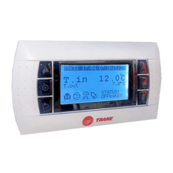
Page 15: User Interface Display
User interface display Figure 4 – LCD Display Sound power levels Discharge Measurement conditions: Measurements taken in a room adjacent to the room containing the FWD, at the outlet of the rectangular duct (1.5 m long) fixed to its discharge opening. Power level in dB(A), per Hz frequency band Overall power Unit... - Page 16 User interface display Technical Data Figure 5 - Deluxe touchscreen display Power supply (V/Ph/Hz) 230/1/50 Capacities Cooling capacity on water (1) (kW) 18,8 30,1 Heating capacity on water (2) (kW) 11,9 18,9 20,9 38,2 Fan motor (type) 2 x direct drive centrifugal Fan power input (3) (kW) 0,23...
-
Page 17: Data Display Menu
Daily/weekly program sub-menu Discharge Unit configuration sub-menu (accessible to Trane technicians only, not accessible to end users) Measurement conditions: Measurements taken in a room adjacent to the room containing the FWD, at the outlet of the rectangular duct (1.5 m The sub-menu will be selected using the Up and Down keys and selected using the Enter button. -
Page 18: Configuration Menu
Heating capacity (4) (kW) 17,4 22,4 34,5 Shows and allows modification of unit configuration with 2 user levels (Local technician and Trane service G2 filter (filter box accessory) technician): Quantity Local technician (by default password = 0005) allows to: Dimensions ( LxWxth) - Page 19 User interface display Sound power levels Discharge Measurement conditions: Measurements taken in a room adjacent to the room containing the FWD, at the outlet of the rectangular duct (1.5 m long) fixed to its discharge opening. Power level in dB(A), per Hz frequency band Overall power Unit speed...
- Page 20 Trane optimizes the performance of homes and buildings around the world. A business of Ingersoll Rand, the leader in creating and sustaining safe, comfortable and energy efficient environments, Trane offers a broad portfolio of advanced controls and HVAC systems, comprehensive building services and parts. For more information visit www.Trane.com...