Table of Contents
Advertisement
Quick Links
Advertisement
Table of Contents

Related Manuals for VeriFone K450


Summary of Contents for VeriFone K450
- Page 1 K450 Installation Guide Verifone Part Number DOC500-009-EN-A, Revision A...
- Page 2 Verifone, Inc. The information contained in this document is subject to change without notice. Although Verifone has attempted to ensure the accuracy of the contents of this document, this document may include errors or omissions. The examples and sample programs are for illustration only and may not be suited for your purpose.
-
Page 3: Table Of Contents
Setup K450 Installation Safety Instructions ....... . . 15 Inside the Shipping Carton ......... 17 Installing K450 . - Page 4 Caution and K450 Caution and Warning Messages ....... . 39...
-
Page 5: Preface
Messages. Shows the UL/cUL Listing compliant translations of all Warning and Caution messages in this installation guide. Related To learn more about the K450, refer to the following set of documents and their Documentation associated Verifone Part Numbers (VPNs). K450 Certifications and Regulations... -
Page 6: Conventions And Acronyms
Acronym Definitions Acronym Definitions CTLS Contactless Europay, MasterCard and Visa Integrated Circuit Light-Emitting Diode Merchandise Return Authorization Near Field Communication Radio Frequency RJ45 Registered Jack 45 Modular Connector Single CI Single Contactless Interface SubMiniature version A connector K450 I NSTALLATION UIDE... -
Page 7: Device Overview
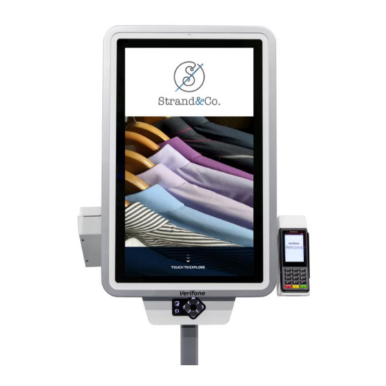
HAPTER Device Overview The K450's beautiful design and large 27" screen creates a powerful magnetic customer attraction. Bring your brand to life with rich graphics that are eye- catching and dynamically disrupt traffic patterns. Its modular design can be configured to meet all of your self-service needs across your organization. It can be mounted as a floor standing kiosk with wiring routed through the floor or above the floor, or from the ceiling. -
Page 8: Features And Benefits
The following features of the device simplifies transactions in various environments: • K450 device is the most modern, slim and yet fully featured kiosk currently available. • Can be ordered as a single-sided or dual-sided pole mountable; or, as wall mountable. -
Page 9: Connectivity
Single-sided pole and wall mount units support 2 ethernet connections; dual- sided pole mount unit supports 4 ethernet connections. • Power and ground from facilities main through either the bottom or top poles. • Optional wireless connectivity. K450 I NSTALLATION UIDE... - Page 10 EVICE VERVIEW Features and Benefits THIS PAGE IS INTENTIONALLY LEFT BL ANK K450 I NSTALLATION UIDE...
-
Page 11: Specifications
HAPTER Specifications K450 This chapter lists the power requirements and other specifications of Specifications the K450 unit. Standard Specifications Processor Intel i5 or i7, Qualcomm Snapdragon Memory 8GB or 16GB Storage 128GB or 256GB SSD Windows 10, Linux, Chrome OS, Android Display 27"... -
Page 12: K450 Specifications
PECIFICATIONS K450 Specifications K450 Specifications K450 SS - Single-Side Pole Mounted Figure 2 K450 I NSTALLATION UIDE... - Page 13 PECIFICATIONS K450 Specifications K450 DS - Dual-Sided Pole Mount Figure 3 K450 WM - Wall Mountable Figure 4 K450 I NSTALLATION UIDE...
- Page 14 PECIFICATIONS K450 Specifications THIS PAGE IS INTENTIONALLY LEFT BL ANK K450 I NSTALLATION UIDE...
-
Page 15: Setup K450 Installation Safety Instructions
Floor Mounting Please ensure to install K450 unit on a suitable, hard, stable floor or surface. K450 unit must be secured to the surface with provided anchor bolts or other suitable anchors for its intended use. Notify Verifone if you have questions about your floor or mounting hardware. - Page 16 It is recommended to periodically inspect the product and its fixing points to ensure that safety is maintained. The response time, brightness and colors of K450 unit may be affected by the ambient temperature. Tiny spots (dark or luminescent) may appear on the display due to the liquid crystal characteristics.
-
Page 17: Inside The Shipping Carton
Do not use a tampered or a damaged unit. The device comes equipped with WARNING tamper-evident labels. If a label or component appears damaged, please notify the shipping company and your Verifone service provider immediately. K450 I NSTALLATION UIDE... -
Page 18: Installing K450
ETUP Installing K450 - K450 Unit Figure 5 Installing K450 Installing Tools and Materials • Adjustable Wrench • Security Hex Key (Provided) • Small Open-End Wrenches • Set of Allen Wrenches, Ball End • Small Socket Set • Needle Nose Pliers •... -
Page 19: Field Wiring 1
ETUP Installing K450 before installation or in a laboratory or other temporary location, an optional stability plate is available. Field Wiring 1 All lines are routed inside the building within a grounded conduit (recommended ½" diameter terminated by a ¾" Romex connector). -
Page 20: Power And Data Lines From Floor
ETUP Installing K450 Lift kiosk and align slots in base to anchors. Carefully lower the kiosk onto anchor bolts and secure with washers and nuts. Ensure nuts are properly tightened. Power and Data If power and data lines come from the ceiling, skip to next section. -
Page 21: Base Cover Installation
ETUP Installing K450 • Green (Ground) to Ground Nut • Black (Hot) to Black (Hot) • White (Neutral) to White (Neutral) Base Cover Remove screws from base. Installation Place covers on base and ensure center tabs interlock. K450 I NSTALLATION... -
Page 22: Top Pole Installation
ETUP Installing K450 Reinsert screws and tighten. Top Pole Installation Install the top pole onto the top of the kiosk and secure the bolts in place using supplied nut hardware. K450 I NSTALLATION UIDE... -
Page 23: Top Pole Extension
ETUP Installing K450 Top Pole Parts Top Pole Extension If ceiling is higher than 10 feet, a Top Pole Extension is required. STEP 1: REMOVE TOP POLE DO NOT drill holes near electrical wires. Disconnect power lines from kiosk before installing top pole extension. - Page 24 ETUP Installing K450 Align the inside divider plate in the top pole extension with the divider in the top pole with the "POWER ONLY" labels on the same side. Slide the top pole extension onto the top pole until it stops.
- Page 25 ETUP Installing K450 Power & Data Lines from Ceiling If power and data lines come from the ceiling, see previous page. Start at the top of the top pole. Guide power cables down through the top pole. CAUTION There is a divider inside the top pole to separate power and data lines. DO NOT run power and data through the same side.
-
Page 26: Wall Mounting
ETUP Installing K450 Wall Mounting Hang the kiosk on the bracket and secure with ¼-20 nuts and washers K450 I NSTALLATION UIDE... -
Page 27: Operation
ETUP Installing K450 Operation Opening Kiosk Open monitor panel by unlocking side of the cabinet, Figure 5, and pulling the display forward firmly. WARNING ELECTRICAL HAZARD RISK - Inside of kiosk contains power wires and electronic devices. Only authorized personnel should open kiosk. Take necessary precautions when working with electrical equipment. -
Page 28: Removing Cabinet Rear Panel
ETUP Installing K450 Cabinet Lock Figure 6 Removing Cabinet A rear service panel provides additional access to internal components and Rear Panel wiring. Only authorized personnel should remove panel. To remove: • Open monitor panel. (See Opening Kiosk). • From inside the cabinet, pull the pin on the left of the cabinet. -
Page 29: Connecting Data Line To Payment Device
ETUP Installing K450 K450 I NSTALLATION UIDE... - Page 30 ETUP Installing K450 Connecting Data Connect one data line to the dongle of the payment device. Secure extra cable Line to Payment with cable ties. Device NOTE The payment device hub will be located in the cabinet. Connect the data line to the available network jack on the hub.
-
Page 31: Connecting Devices 1
ETUP Installing K450 Connecting Devices 1 Connect power to the touchscreen monitor with its provided power adapter located inside the cabinet. Connect power to the computer with its power adapter located inside the cabinet. Connect the USB cable from the ADA keypad device to the computer. - Page 32 ETUP Installing K450 THIS PAGE IS INTENTIONALLY LEFT BL ANK K450 I NSTALLATION UIDE...
-
Page 33: Maintenance And Cleaning
These suggestions apply equally to your contactless device, or any of its attachments or accessories. If your device is not working properly, take it to the nearest Verifone-authorized service provider for servicing or replacement. Additional The following is additional information for your safety in using this device. - Page 34 AINTENANCE AND LEANING Additional Safety Information THIS PAGE IS INTENTIONALLY LEFT BL ANK K450 I NSTALLATION UIDE...
-
Page 35: Verifone Service And Support
NOTE For international customers, please contact your local Verifone representative for assistance with your service, return, or replacement. Get the following information from the printed labels at the back of each K450 to be returned: • Product ID, including the model and part number. For example, “K450” and “M500-XXX-XXX-XXX.”... -
Page 36: Accessories And Documentation
• Reference the model and part number in the Note box. NOTE One MRA number must be issued for each K450 you return to Verifone, even if you are returning several of the same model. Describe the problem(s). Provide the shipping address where the repaired or replacement unit must be returned. -
Page 37: Troubleshooting Guidelines
HAPTER Troubleshooting Guidelines The troubleshooting guidelines provided in the following section are included to assist you to successfully install and configure your K450 Kiosk. If you have problems operating your K450 Kiosk, please read through these troubleshooting examples. If the problem persists even after performing the outlined guidelines or if the problem is not described below, contact your local Verifone representative for assistance. - Page 38 ROUBLESHOOTING UIDELINES Peripheral Device Does Not Work THIS PAGE IS INTENTIONALLY LEFT BL ANK K450 I NSTALLATION UIDE...
-
Page 39: A P P En Di
If a label or component semble endommagé, se il vous plaît appears damaged, please aviser la compagnie de navigation et notify the shipping company votre fournisseur de services Verifone and your Verifone service immédiatement. provider immediately. Observer les précautions standard dans... - Page 40 Verifone, Inc. 1-800-Verifone www.verifone.com K450 Installation Guide Verifone Part Number DOC500-009-EN-A, Revision A...