
Related Manuals for Baumer Hubner HMC16 Series


Summary of Contents for Baumer Hubner HMC16 Series
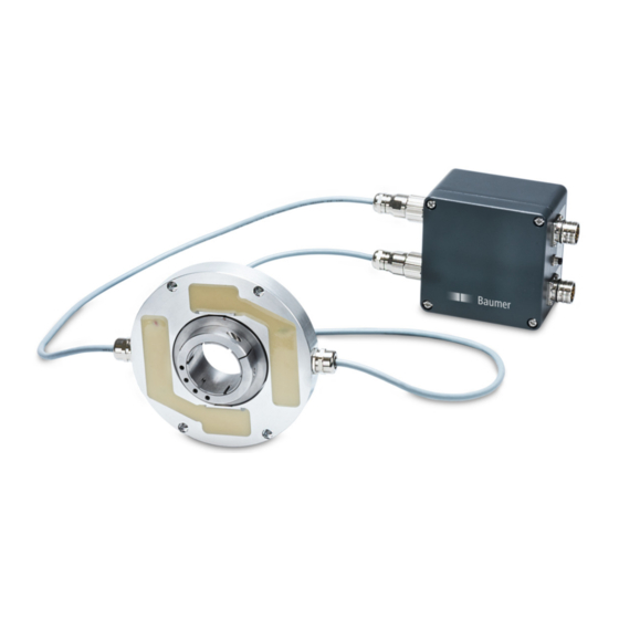
- Page 1 Mounting and operating instructions HMC16 ... Encoder without bearings - incremental Magnetic sensing with signal processing electronics (1 or 2 signal outputs)
-
Page 2: Table Of Contents
TABLE OF CONTENTS TABLE OF CONTENTS 1. IMPORTENT NOTES �������������������������������������������������������������������������������������������������������������1 1�1 Symbol guide ������������������������������������������������������������������������������������������������������������������1 1�2 Intended use �������������������������������������������������������������������������������������������������������������������1 1�3 Exclusion from liability ����������������������������������������������������������������������������������������������������1 1�4 Maintenance and lifetime ������������������������������������������������������������������������������������������������2 1�5 Approvals and warranty ��������������������������������������������������������������������������������������������������2 1�6 Operating and storage temperature range ���������������������������������������������������������������������2 1�7 Disposal (environmental protection) �������������������������������������������������������������������������������2 2. - Page 3 TABLE OF CONTENTS 6. ELECTRICAL CONNECTION ����������������������������������������������������������������������������������������������12 6�1 Functional principle HMCP16 ���������������������������������������������������������������������������������������12 6.2 Part number definition HMCP16 �����������������������������������������������������������������������������������13 6�2�1 Overview ���������������������������������������������������������������������������������������������������������13 6�2�2 Table „Output“ �������������������������������������������������������������������������������������������������13 6�2�3 Table „Pulses (periods)“ ����������������������������������������������������������������������������������14 6�2�4 Table „Frequency output“ ��������������������������������������������������������������������������������14 6�2�5 Table „Power supply“ ��������������������������������������������������������������������������������������14 6.2.6 Table „Envelope delay time of the filter in µs“ �������������������������������������������������14 6�3 Connecting HMCP16 to HMCK16 ��������������������������������������������������������������������������������15 6.4 Terminal significance ����������������������������������������������������������������������������������������������������15 6�5 Pin assignment mating connector HMCK16 �����������������������������������������������������������������16...
- Page 4 TABLE OF CONTENTS 7. SETTINGS HMCP16 ������������������������������������������������������������������������������������������������������������24 7�1 Removing the cover ������������������������������������������������������������������������������������������������������24 7�2 Pin headers on the electronic board �����������������������������������������������������������������������������25 7�2�1 Electronic board version 1 ������������������������������������������������������������������������������25 7�2�2 Electronic board version 2 ������������������������������������������������������������������������������25 7�3 Adjustment of the interpolation of the pulses (cycles) ��������������������������������������������������26 7�4 Adjustment of the frequency output ������������������������������������������������������������������������������27 7.5 Adjustment of the envelope delay time of the filter �������������������������������������������������������28 7�6 Adjustment to skeleton operation ���������������������������������������������������������������������������������28...
-
Page 5: Importent Notes
IMPORTENT NOTES IMPORTENT NOTES Symbol guide Warning Disregarding could result in serious injury, death or damage to property Attention Disregarding could result in damage to property or damage/malfunction of the device Information Additional information and recommendations Intended use The bearingless encoder HMC16 is a precision measurement device for the acquisition of speed/position information for the control of drive units and the provision of electronic output signals for downstream devices�... -
Page 6: 1�4 Maintenance And Lifetime
Whenever possible, waste electrical and electronic equipment should be disposed locally at the authorized collection point� If necessary, Baumer gives customers the opportunity to dispose of Baumer products professionally� For further information see www�baumer�com�... -
Page 7: Safety And Attention Instructions
SAFETy AND ATTENTION INSTRUCTIONS SAFETY AND ATTENTION INSTRUCTIONS Safety instructions Explosion risk Spark formation can cause a fire or an explosion. » Do not use the device in areas with explosive and/or highly infl ammable materi- als. They may explode and/or catch fire by possible spark formation. Risk of serious injuries due to rotating shafts Hair and clothes may become tangled in rotating shafts� Touching the rotating parts can cause extremely serious injuries� »... -
Page 8: 2�2 Attention Instructions For Mounting And Operation
SAFETy AND ATTENTION INSTRUCTIONS Attention instructions for mounting and operation Risk of destruction due to electrostatic charge Electronic parts contained in the device are sensitive to high voltages� » Do not touch plug contacts or electronic components� » Protect output terminals against external voltages� »... -
Page 9: Preparation
PREPARATION PREPARATION Overview complete system A single component must not operating separately because it does not work or damaged� The encoder without bearings HMC16 is an complete system with following single com- ponents: 1) HMCR16 - Rotor with magnetic material measure 2) HMCK16 - Stator with up to 2 integrated sensing heads 3) HMCP16 - Signal processing electronic with 1-2 inputs and 1-2 outputs This complete system can only operating completely because each single component is... -
Page 10: 3�2 Scope Of Delivery Single Component „Rotor - Hmcr16
PREPARATION Scope of delivery single component „Rotor - HMCR16“ Rotor HMCR16 Clamping ring Clamping ring screw ISO 4762, M4x16 Part number single component - HMCR16 Without zero pulse Device name With zero pulse H M C R 1 6 Variant Revision Hollow shaft diameter in mm Scope of delivery single component „Stator - HMCK16“... -
Page 11: 3�4 Scope Of Delivery Single Component „Signal Processing Electronic - Hmcp16
PREPARATION Scope of delivery single component „Signal processing electronic - HMCP16“ Signal processing electronic HMCP16 Flange connector input M23, 12-pin, female contacts, counter-clockwise, section 6.7� 10 Flange connector output M23, 12-pin, male contacst, counter-clockwise, section 6.8� 11 External power supply M8 connector, 3-pin, male contacts, see section 6.9�... -
Page 12: 3�5 Required For Mounting (Not Included In Scope Of Delivery)
PREPARATION Required for mounting (not included in scope of delivery) Connecting cables and mating connectors are also required for the electrical connection� 12 4 fixing screws M5x25, DIN ISO 4762 for fixing the stator HMCK16 Required for dismounting (not included in scope of delivery) 13 4 jack screws M6x35, DIN ISO 4762 for dismounting the stator HMCK16 Required tools (not included in scope of delivery) 3, 4 und 5 mm... -
Page 13: Mounting
MOUNTING / LOOSEN THE CLAMPING RING SCREW MOUNTING Loosen the clamping ring screw » Loosen the clamping ring screw a little bit� Mounting to drive shaft Service life restrictions and angle error by runouts High runout of the drive shaft can cause device angle error� High runout of the drive shaft can cause vibrations, which can shorten the service life of the device�... -
Page 14: 4�3 Tighten The Clamping Ring Screw And Adjust The System
MOUNTING / TIGHTEN THE CLAMPING RING SCREW AND ADjUST THE SySTEM Tighten the clamping ring screw and adjust the system Check the flush alignment of the rotor and the stator front edge and adjust correct distance between stator and clamping ring front edge, see figure. 0�4 mm Nominal air gap Max� tightening torque: 15 mm = 3���4 Nm +0�2 mm -0�2 mm * Siehe page 6 10/40 MB168T1EN - 11184527, 19A2, Baumer_HMC16-T1_II_EN... -
Page 15: Dimensions
DIMENSIONS DIMENSIONS HMCR16 and HMCK16 Multiple Positive rotating sensing direction Length 2 m 4x fixing hole for M5 thread to dab off M6 ød1 ød2 60�5 70�5 HMCP16 View B Input 1 Input 2 Ground connection View C Output 2 Output 1 Depending on the version External power supply All dimensions in millimeters, unless otherwise stated)�... -
Page 16: Electrical Connection
ELECTRICAL CONNECTION / FUNCTIONAL PRINCIPLE HMCP16 ELECTRICAL CONNECTION Functional principle HMCP16 The differential SinCos encoder signals, connected to the input, are converted into TTL, HTL, SinCos output signals with interpolated pulses/cycles and/or SSI output (speed and position), frequency output� The zero pulse is adjusted as well if available� Zero pulse signals R+ and R- (output 1 and 2) are determined on the basis of the input signals R+ and R- of the inputs 1 and 2 up to a speed of ~1000 rpm�... -
Page 17: Part Number Definition Hmcp16
ELECTRICAL CONNECTION / PART NUMBER DEFINITION HMCP16 Part number definition HMCP16 6.2.1 Overview H M C P 1 6 X 0 0 Output 1, see Table „Output“ in section 6.2.2 Output 2, see Table „Output“ in section 6.2.2 Power supply, Table „Power supply“... -
Page 18: 6�2�3 Table „Pulses (Periods)
ELECTRICAL CONNECTION / PART NUMBER DEFINITION HMCP16 6.2.3 Table „Pulses (periods)“ y (factory setting) 1024 1024 2048 4096 2048 4096 8192 16384 Example 8192 16384 32768 65536 32768 65536 131072 262144 6.2.4 Table „Frequency output“ y (factory setting) rpm = Speed, kHz = Output frequency -3000 -9000 -16000... -
Page 19: 6�3 Connecting Hmcp16 To Hmck16
ELECTRICAL CONNECTION / CONNECTING HMCP16 TO HMCK16 Connecting HMCP16 to HMCK16 View X section 6.5 Hand-tight Terminal significance Voltage supply Ground HTL/TTL/SinCos channel 1 A– HTL/TTL/SinCos channel 1 inverted HTL/TTL/SinCos channel 2 (offset by 90° to channel 1) B– HTL/TTL/SinCos channel 2 inverted HTL/TTL/SinCos zero pulse (reference signal) R–... -
Page 20: 6�5 Pin Assignment Mating Connector Hmck16
ELECTRICAL CONNECTION / PIN ASSIGNMENT MATING CONNECTOR HMCK16 Pin assignment mating connector HMCK16 Output stage SinCos 1 V , 128 sinewave cycles per turn, mating connector M23, 12-pin, male contacts, clockwise View X see section 6.3 The flanks of the systems signals are not synchronised at version with multiple magnetic sensing� Assignment B–... -
Page 21: 6�7 Inputs Hmcp16
ELECTRICAL CONNECTION / INPUTS HMCP16 Inputs HMCP16 6.7.1 Input 1 (and 2): SinCos Flange connector M23, 12-pin, female contacts, counter-clockwise Assignment B– dnu / R+ dnu / R– A– +UB (5 VDC) Outputs HMCP16 6.8.1 Output signals depending on the version 6.8.1.1 SinCos 360°... -
Page 22: 6�8�1�3 Ssi Telegram
ELECTRICAL CONNECTION / OUTPUTS HMCP16 6.8.1.3 SSI telegram Clock frequency = 100 kHz���1 MHz SSI1 CL– / CL+ 15 μs SSI1 DA– / DA+ 30 29 27 26 Speed word Error (nE) Odd Parity (the number of all ones, included this bit is odd) Clock frequency = 100 kHz���1 MHz SSI2 CL–... -
Page 23: Connection Assignment
ELECTRICAL CONNECTION / OUTPUTS HMCP16 6.8.2 Connection assignment 6.8.2.1 Output 1 „S“: SinCos 1 V Flange connector M23, 12-pin, male contacts, counter-clockwise Assignment B– dnu / R+ dnu / R– A– dnu / +UB (10���30 VDC) 6.8.2.2 Output 1 „A“: SinCos 1 V + error output TTL level Flange connector M23, 12-polig, male contacts, counter-clockwise There is an inverted error signal via pin 7 available�... -
Page 24: 6�8�2�3 Output 1 (Or 2) „H" Or „T": Htl Or Ttl
ELECTRICAL CONNECTION / OUTPUTS HMCP16 6.8.2.3 Output 1 (or 2) „H“ or „T“: HTL or TTL Flange connector M23, 12-polig, male contacts, counter-clockwise Assignment B– dnu / R+ dnu / R– A– dnu / +UB (10���30 VDC) 6.8.2.4 Output 1 (or 2) „U“: Universal HTL/TTL Flange connector M23, 12-polig, male contacts, counter-clockwise Assignment B–... -
Page 25: 6�8�2�5 Output 1 (Or 2) „B": Ttl + Error Output Ttl Level
ELECTRICAL CONNECTION / OUTPUTS HMCP16 6.8.2.5 Output 1 (or 2) „B“: TTL + error output TTL level Flange connector M23, 12-polig, male contacts, counter-clockwise There is an inverted error signal via pin 7 available� In case of failure it has an output of 0 V�... -
Page 26: 6�8�2�7 Output 1 (Or 2) „P": Universal Htl/Ttl + Error Output Ttl Level
ELECTRICAL CONNECTION / OUTPUTS HMCP16 6.8.2.7 Output 1 (or 2) „P“: Universal HTL/TTL + error output TTL level Flange connector M23, 12-polig, male contacts, counter-clockwise There is an inverted error signal via pin 7 available� In case of failure it has an output of 0 V�... -
Page 27: 6�8�2�9 Output 1 (Or 2) „F": Ttl Frequency Output
ELECTRICAL CONNECTION / CONNECTION ASSIGNMENT ExTERNAL POWER SUPPLy „E“ HMCP16 6.8.2.9 Output 1 (or 2) „F“: TTL frequency output Output of the linear frequency modulated speed� The output square wave signal fB is offset by 90° to fA� The signal fA is always running ahead of signal fB� Flange connector M23, 12-polig, male contacts, counter-clockwise Assignment fB–... -
Page 28: Settings Hmcp16
SETTINGS HMCP16 / REMOVING THE COVER SETTINGS HMCP16 Removing the cover The output pulses (cycles), the envelope delay time of the filter and the adjustment to skeleton operation can be adjusted via jumpers on the electronic board, see section 7.2� The cover has to be removed first. 24/40 MB168T1EN - 11184527, 19A2, Baumer_HMC16-T1_II_EN... -
Page 29: 7�2 Pin Headers On The Electronic Board
SETTINGS HMCP16 / PIN HEADERS ON THE ELECTRONIC BOARD Pin headers on the electronic board 7.2.1 Electronic board version 1 Pin header 1 (output 1 and envelope delay time of the filter) Pin header 2 (output 2 and skeleton operation) 7.2.2 Electronic board version 2 Pin header 1 (output 1 and envelope delay time of the filter) Pin header 2 (output 2 and skeleton operation) MB168T1EN - 11184527, 19A2, Baumer_HMC16-T1_II_EN 25/40... -
Page 30: 7�3 Adjustment Of The Interpolation Of The Pulses (Cycles)
SETTINGS HMCP16 / ADjUSTMENT OF THE INTERPOLATION OF THE PULSES (CyCLES) Adjustment of the interpolation of the pulses (cycles) Adjustment of the interpolation of the pulses (cycles) of output 1 (pin header 1) and output 2 (pin header 2)� The output pulses (cycles) can be adjusted via 3 different jumper positions on the corre- sponding pin header on the electronic board, see 7.2.2, to higher section 7.2.1... -
Page 31: 7�4 Adjustment Of The Frequency Output
SETTINGS HMCP16 / ADjUSTMENT OF THE FREqUENCy OUTPUT Adjustment of the frequency output Adjustment of the freqency output of output 1 (pin header 1) and output 2 (pin header 2)� The frequency output can be adjusted via 3 different jumper positions on the correspon- ding pin header on the electronic board, see 7.2.2, to higher or section 7.2.1... -
Page 32: Adjustment Of The Envelope Delay Time Of The Filter
SETTINGS HMCP16 / ADjUSTMENT OF THE ENVELOPE DELAy TIME OF THE FILTER Adjustment of the envelope delay time of the filter Adjustment of the envelope delay time of the filter (pin header 1) The factory setting and ordered value for the envelope delay time of the filter can be set in 3 different values via jumper positions on the pin header on the electronic board, see section 7.2.1 section 7.2.2�... -
Page 33: Filter Diagrams Hmcp16
FILTER DIAGRAMS HMCP16 FILTER DIAGRAMS HMCP16 Filterdiagrams for the different envelope delay time Filter setting „00“ (range 150 µs) Filter "00", group delay = 170 μs -100 Frequency [Hz] Filter setting „01“ (range 300 µs) Filter "01", group delay = 298 μs -100 Frequency [Hz] MB168T1EN - 11184527, 19A2, Baumer_HMC16-T1_II_EN... -
Page 34: Filter Setting „02" (Range 500
FILTER DIAGRAMS HMCP16 Filter setting „02“ (range 500 µs) Filter "02", group delay = 553 μs -100 Frequency [Hz] Filter setting „03“ (range 1000 µs) Example of section 6.2.6� Filter "03", group delay = 1063 μs -100 Frequency [Hz] 30/40 MB168T1EN - 11184527, 19A2, Baumer_HMC16-T1_II_EN... -
Page 35: 8�5 Filter Setting „10" (Range 0�5
FILTER DIAGRAMS HMCP16 Filter setting „10“ (range 0.5 ms) Filter "10", group delay = 589 μs -100 Frequency [Hz] Filter setting „11“ (range 1 ms) Filter "11", group delay = 1099 μs -100 Frequency [Hz] MB168T1EN - 11184527, 19A2, Baumer_HMC16-T1_II_EN 31/40... -
Page 36: 8�7 Filter Setting „12" (Range 2
FILTER DIAGRAMS HMCP16 Filter setting „12“ (range 2 ms) Filter "12", group delay = 2119 μs -100 Frequency [Hz] Filter setting „13“ (range 4 ms) Filter "13", group delay = 4159 μs -100 Frequency [Hz] 32/40 MB168T1EN - 11184527, 19A2, Baumer_HMC16-T1_II_EN... -
Page 37: Dismounting
DISMOUNTING / DISMOUNTING THE SIGNAL PROCESSING ELECTRONIC HMCP16 DISMOUNTING Dismounting the signal processing electronic HMCP16 Untighten the clamping ring screw » Untighten the clamping ring screw a little bit� * See page 6 page 7 MB168T1EN - 11184527, 19A2, Baumer_HMC16-T1_II_EN 33/40... -
Page 38: 9�3 Removing The Rotor From The Drive Shaft
DISMOUNTING / REMOVING THE ROTOR FROM THE DRIVE SHAFT Removing the rotor from the drive shaft Unscrewing the fixing screws of the stator * See page 6 page 8 34/40 MB168T1EN - 11184527, 19A2, Baumer_HMC16-T1_II_EN... -
Page 39: 9�5 Screwing In The Jack Screws In Stator
DISMOUNTING / SCREWING IN THE jACK SCREWS IN STATOR Screwing in the jack screws in stator Getting off the stator from the drive shaft * See page 8 MB168T1EN - 11184527, 19A2, Baumer_HMC16-T1_II_EN 35/40... -
Page 40: Technical Data
TECHNICAL DATA TECHNICAL DATA 10.1 Technical data - electrical ratings Generation of the output signals with the external signal processing electronic HMCP16 Power supply: 10���30 VDC (HMCP16) * 5 VDC ±5 % (HMCK16 via HMCP16) * Consumption: ~200 mA (at 15 VDC) Interference immunity: EN 61000-6-2 Emitted interference:... - Page 41 TECHNICAL DATA TTL frequency output * Output signals: fA+, fA–, fB+, fB– Output frequency: 5 / 15 / 25 kHz* -3000 / 0 / +3000 rpm -9000 / 0 / +9000 rpm -16000 / 0 / +16000 rpm -25600 / 0 / +25600 rpm 50 / 100 / 150 kHz* -3000 / 0 / +3000 rpm -9000 / 0 / +9000 rpm -16000 / 0 / +16000 rpm...
-
Page 42: 10�2 Technical Data - Mechanical Design (Hmcr16 + Hmck16)
TECHNICAL DATA 10.2 Technical data - mechanical design (HMCR16 + HMCK16) Operating speed (mechanical): 25000 rpm (at speed of >10000 rpm the drive shaft must have a runout of 0�01 mm) Rotor moment of inertia: 7�5 kgcm (ø45 mm) Resistance: IEC 60068-2-6 Vibration 25 g, 10-2000 Hz IEC 60068-2-27 Shock 300 g, 12 ms Protection DIN EN 60529: IP68... - Page 43 MB168T1EN - 11184527, 19A2, Baumer_HMC16-T1_II_EN...
- Page 44 Baumer Hübner GmbH P.O. Box 12 69 43 · 10609 Berlin, Germany Phone: +49 (0)30/69003-0 · Fax: +49 (0)30/69003-104 info@baumerhuebner.com · www.baumer.com/motion MB168T1EN - 11184527, 19A2 (26�09�2019), Baumer_HMC16-T1_II_EN...