
Related Manuals for Fluke DTX Series


Summary of Contents for Fluke DTX Series
- Page 1 DTX Series CableAnalyzer Technical Reference Handbook April 2004 © 2004 Fluke Corporation. All rights reserved. All product names are trademarks of their respective companies.
- Page 2 LIMITED WARRANTY AND LIMITATION OF LIABILITY Each Fluke Networks product is warranted to be free from defects in material and workmanship under normal use and service. The warranty period is one year and begins on the date of purchase. Parts, accessories, product repairs and services are warranted for 90 days. This war-...
- Page 3 Chapter Title Page Getting Acquainted...................... 1-1 Overview of Features ....................1-1 Registration ........................1-2 Contacting Fluke Networks ..................1-2 Additional Resources for Cable Testing Information ..........1-3 Unpacking........................1-3 DTX-1800........................1-3 DTX-1200........................1-4 DTX-LT........................1-4 DTX-MFM Multimode Fiber Modules (optional)............ 1-5 DTX-SFM Singlemode Fiber Modules (optional) ............
- Page 4 DTX Series CableAnalyzer Technical Reference Handbook Verifying Operation ....................1-21 Checking the Hardware and Software Versions............. 1-22 The Main Autotest Screen ..................1-22 Setting User Preferences....................1-24 Changing the Date, Time, and Date/Time Formats..........1-24 Changing the Length Units ..................1-24 Adjusting the Display Contrast................
- Page 5 Contents (continued) with Twisted Pair Adapters..................2-7 Step 2: Selecting a Cable Type and Test Limit............2-8 Step 3: Running the Autotest ................. 2-8 Step 4: Viewing the Autotest Results ..............2-11 Step 5: Saving the Results ..................2-12 Certifying Fiber Cabling ....................2-12 Required Equipment ....................
- Page 6 DTX Series CableAnalyzer Technical Reference Handbook PASS*/FAIL* Results....................3-12 Wire Map........................3-13 Resistance ......................... 3-15 Characteristic Impedance..................3-15 Length........................3-16 Propagation Delay and Delay Skew ................ 3-17 Insertion Loss......................3-18 NEXT (Near-End Crosstalk)..................3-20 ACR (Attenuation to Crosstalk Ratio) ..............3-22 Return Loss .......................
- Page 7 Contents (continued) Certifying Fiber Optic Cabling ..................5-1 Overview of Features ....................5-1 Physical Features...................... 5-3 Installing and Removing Fiber Modules..............5-4 Verifying Operation ....................5-4 Essentials for Reliable Fiber Test Results ..............5-5 Cleaning Connectors and Adapters ................ 5-5 About Setting the Reference ..................
- Page 8 DTX Series CableAnalyzer Technical Reference Handbook Using FindFiber in Smart Remote Mode ..............5-40 Using FindFiber in Loopback Mode................. 5-44 Using the Power Meter....................5-46 Running Single Tests..................... 5-49 Using the Remote Tester with an OptiFiber Tester..........5-49 Locating Fibers and Faults with the Visual Fault Locator .......... 6-1 Visual Fault Locator Applications.................
- Page 9 Contents (continued) Uploading Results to a PC.................... 8-9 Maintenance and Specifications ................. 9-1 Maintenance......................... 9-1 Reference Procedure for Link Interface Adapters ..........9-1 Factory Calibration ....................9-2 Updating the Tester’s Software ................9-2 Cleaning ........................9-5 Resetting the Battery Gauge................... 9-6 Replacing the Battery....................
- Page 10 DTX Series CableAnalyzer Technical Reference Handbook Characteristic Impedance..................9-26 Impulse Noise ......................9-26 DTX-MFM/DTX-SFM Fiber Module Specifications........... 9-27 Visual Fault Locator....................9-31 Tone Generator......................9-31 Power........................9-32 Electromagnetic Compatibility................9-32 Input Ratings ......................9-32 Certification and Compliance.................. 9-32 CSA Standards ......................9-33 Safety ........................
- Page 11 List of Tables Table Title Page 1-1. International Electrical Symbols ..................1-6 3-1. Twisted Pair Test Settings ....................3-3 3-2. Smart Remote Requirements for Single Tests..............3-30 4-1. Diagnosing Twisted Pair Test Failures ................4-2 5-1. TIA/EIA-568-B.1 and ISO/IEC TR 14763-3 Mandrel Requirements........5-7 5-2.
- Page 12 DTX Series CableAnalyzer Technical Reference Handbook...
- Page 13 List of Figures Figure Title Page 1-1. Tester Front Panel Features ....................1-8 1-2. Tester Side and Top Panel Features..................1-10 1-3. Smart Remote Features ....................... 1-12 1-4. Charging and Removing the Battery.................. 1-16 1-5. Checking the Battery Status....................1-18 1-6.
- Page 14 DTX Series CableAnalyzer Technical Reference Handbook 2-7. Equipment for Testing in Smart Remote Mode ..............2-13 2-8. Installing and Removing Fiber Modules ................2-14 2-9. Self Test Connections for Fiber Modules ................2-15 2-10. Smart Remote Mode Reference Connections..............2-17 2-11.
- Page 15 Contents (continued) 3-23. Impulse Noise Test Results ....................3-33 3-24. Using the Tone Generator ....................3-35 4-1. HDTDX Plot .......................... 4-10 4-2. Interpreting HDTDX Plots ....................4-11 4-3. HDTDR Plot .......................... 4-13 4-4. Interpreting HDTDR Plots....................4-14 5-1. Fiber Module Features ......................5-3 5-2.
- Page 16 DTX Series CableAnalyzer Technical Reference Handbook 5-23. Using FindFiber in Loopback Mode ..................5-45 5-24. Equipment for Using the Power Meter ................5-46 5-25. Connections for Monitoring Optical Power ............... 5-47 5-26. Power Meter Screens ......................5-48 6-1. Equipment for Using the Visual Fault Locator ..............6-2 6-2.
- Page 17 • Overview of Features Automatic diagnostics report distance to and likely causes of common faults. The DTX Series CableAnalyzers are rugged, hand-held • Toner feature helps you locate jacks and instruments used to certify, troubleshoot, and document automatically starts an Autotest upon tone twisted pair and fiber cabling installations.
- Page 18 Note • Smart remote with optional fiber module can be used If you contact Fluke Networks about your tester, with Fluke Networks OF-500 OptiFiber Certifying have the tester's software and hardware version OTDR for loss/length certification.
- Page 19 • Unpacking DTX RS-232 serial cable for PC communications • Two ac adapters The DTX Series CableAnalyzers and optional DTX-MFM • DTX Series CableAnalyzer Users Manual and DTX-SFM fiber modules come with the accessories • listed below. If something is damaged or missing, contact DTX Series CableAnalyzer Product CD the place of purchase immediately.
- Page 20 USB cable for PC communications • Two headsets • Two ac adapters • Carrying case • DTX Series CableAnalyzer Users Manual • Carrying strap • DTX Series CableAnalyzer Product CD • USB cable for PC communications • LinkWare Software CD •...
- Page 21 DTX CableAnalyzer Product CD • LinkWare Software CD The patch cords provided are suitable for testing SC-terminated links. Other patch cords are µ required for other connector types or 50 /125 fiber. Many are available as accessories from Fluke Networks.
- Page 22 • Do not modify the tester. Warning: Risk of fire, electric shock, or personal • Use only ac adapters approved by Fluke injury. Networks for use with the DTX tester to charge Warning or Caution: Risk of damage or the battery or power the tester.
- Page 23 Getting Acquainted Safety Information • • Always turn on the tester before connecting it To ensure maximum accuracy of copper cable to a cable. Turning the tester on activates the test results, perform the reference procedure as tool’s input protection circuitry. described under “Setting the Reference”...
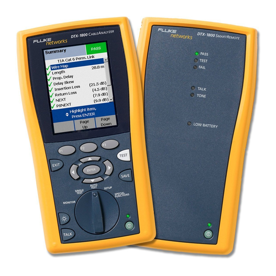
- Page 24 DTX Series CableAnalyzer Technical Reference Handbook Physical Features Basic Features Figures 1-1 and 1-2 describe the tester’s features. Figure The following sections introduce the tester's basic 1-3 describes the smart remote’s features. features. EXIT TEST ENTER SAVE AUTO TEST SINGLE...
- Page 25 Getting Acquainted Basic Features LCD display with backlight and adjustable : Press to turn the display backlight on or off. brightness. Hold for 1 second to adjust the display contrast. H B C A D : Starts the currently selected test. Activates the : Arrow keys for navigating tone generator for twisted pair cabling if no smart through screens and incrementing or decrementing...
- Page 26 DTX Series CableAnalyzer Technical Reference Handbook amd33f.eps Figure 1-2. Tester Side and Top Panel Features 1-10...
- Page 27 DTX-1200) ports for uploading test reports to a PC and updating the tester’s software. The RS-232C port uses a custom DTX cable available from Fluke Networks. See Chapter 9 for more information. Figure 1-2. Tester Side and Top Panel Features (cont.)
- Page 28 DTX Series CableAnalyzer Technical Reference Handbook PASS TEST FAIL TALK TONE LOW BATTERY TEST TALK amd30f.eps Figure 1-3. Smart Remote Features 1-12...
- Page 29 Getting Acquainted Basic Features : Starts the test currently selected on the main Caution unit. Activates the tone generator for twisted pair All the LEDs flash if the smart remote detects cabling if no main tester is detected. The test starts excessive voltage on the cable.
- Page 30 DTX Series CableAnalyzer Technical Reference Handbook Charging the Battery Changing the Language • To charge the battery, connect the ac adapter to the To change the tester’s language: battery pack, as shown in Figure 1-4. Turn the rotary switch to SETUP.
- Page 31 Getting Acquainted Basic Features Charging the battery Removing the battery amd124f.eps Figure 1-4. Charging and Removing the Battery 1-15...
- Page 32 DTX Series CableAnalyzer Technical Reference Handbook Checking the Battery Status Turn the rotary switch to SPECIAL FUNCTIONS. The battery status icon ( ) near the upper-right to highlight Battery Status; then press corner of the tester’s main screens shows the battery’s charge level.
- Page 33 Getting Acquainted Basic Features 91 % - 100 % PASS PASS PASS PASS PASS PASS TEST TEST TEST TEST TEST TEST PASS FAIL FAIL FAIL FAIL FAIL FAIL 75 % - 90 % TALK TALK TALK TALK TALK TALK TEST TONE TONE TONE...
- Page 34 LAN cabling. The channel and permanent link interface adapters provided are suitable for testing cabling up to Cat 6. For information on other adapter types, contact Fluke Networks or visit the Fluke Networks website. EXIT TEST...
- Page 35 Getting Acquainted Basic Features 7 in (18 cm) minimum 7 in (18 cm) minimum radius or bend DSP-7XXX CABLE ANALYZER EXIT EXIT TEST TEST ENTER ENTER SAVE SAVE AUTO AUTO TEST TEST SINGLE SINGLE SETUP SETUP TEST TEST SPECIAL SPECIAL MONITOR MONITOR FUNCTIONS...
- Page 36 DTX Series CableAnalyzer Technical Reference Handbook The DTX-PLA001 universal permanent link adapter has a removable personality module. These may be changed to customize the adapter for different jack configurations. To change the personality module (refer to Figure 1-8): Static sensitive...
- Page 37 Getting Acquainted Basic Features Verifying Operation The tester performs a basic self test when you turn it on. To run a more thorough self test for an acceptance test or as part of a routine equipment check: Connect the main and remote testers as shown in Permanent link adapter Figure 1-9.
- Page 38 Technical Reference Handbook Checking the Hardware and Software Versions To determine if your tester needs a software update, visit the Fluke Networks website to see if an update is To see version information for the tester’s hardware and available. software:...
- Page 39 Getting Acquainted Basic Features The media type selected for testing. Press to change media. Battery status icon. Test Limit: The tester compares test results to the selected limit to determine the PASS/FAIL result. Cable Type: The type of cable to be tested. Press to check the memory status.
- Page 40 DTX Series CableAnalyzer Technical Reference Handbook Changing the Length Units Setting User Preferences Turn the rotary switch to SETUP, use The following sections describe how to change settings highlight Instrument Settings; then press you may want to adjust when you first start using the tester.
- Page 41 Getting Acquainted Setting User Preferences Setting the Power Down Timer Setting the Backlight Timer The power down timer turns off the tester after a selected The backlight timer turns off the backlight after a period of inactivity. The timer starts when the backlight selected period of inactivity.
- Page 42 DTX Series CableAnalyzer Technical Reference Handbook Enabling or Disabling the Beeper Formatting the Memory Card (DTX-1800 and DTX-1200) To enable or disable the tones for key presses and testing progress: To format the memory card: Turn the rotary switch to SETUP, use Insert an MMC or SD memory card into the tester, as highlight Instrument Settings;...
- Page 43 Getting Acquainted Overview of Memory Features DTX-1800, DTX-1200: Press if necessary if you Note want to create the folder on the memory card. If you change storage location, and the selected Current Folder does not exist in the new Press Create Folder.
- Page 44 DTX Series CableAnalyzer Technical Reference Handbook Options for Entering Cable IDs When you save a test, you enter a name for the test. At a job site, you usually name each test with the identification code assigned to the link tested. You can enter this ID character by character, or by selecting the ID from a pre- generated list.
- Page 45 Getting Acquainted Overview of Memory Features The tester offers the following methods for entering cable To create a list of sequential IDs: IDs: On the Auto Sequence screen, select a template. • Auto Increment: You enter an ID for the first test you On the Auto Sequence screen, select Start ID.
- Page 46 LinkWare Getting Started Guide and the online help available under Help on the LinkWare menu. At the smart remote, use to cycle through the Updates to LinkWare software are available on the Fluke volume settings. Networks website. To exit the talk mode at the main tester, press turn the rotary switch to a new position, or start a test.
- Page 47 The LinkWare Stats Statistical Report option for LinkWare software provides statistical analysis of cable test reports and generates browsable, graphical reports. LinkWare software includes a demo version of LinkWare Stats. Contact Fluke Networks or visit the Fluke Networks website for more information on LinkWare Stats. 1-31...
- Page 48 DTX Series CableAnalyzer Technical Reference Handbook 1-32...
- Page 49 Chapter 2 Tutorials on Setup and Test Procedure The tutorials in this chapter guide you through setting up the tester, checking the tester’s status, testing twisted pair and fiber cabling, and setting up cable ID lists. Preparing to Save Tests Step 1: Checking the Memory Space Available 1-1 DTX-1800, DTX-1200: Insert a memory card into the tester.
- Page 50 DTX Series CableAnalyzer Technical Reference Handbook BCAD Step 2: Entering Job Information 2-4 Use , and enter your name in the box. Press when you are Job information includes the operator name, name of done. the job site, and the customer’s company name. These settings are stored with results you save.
- Page 51 Tutorials on Setup and Test Procedure Preparing to Save Tests The characters available for use. To select a character to enter in the text box, use ADBC to highlight the character; then press The character is entered to the left of the cursor. The text you are entering.
- Page 52 DTX Series CableAnalyzer Technical Reference Handbook Step 4: Setting the Storage Location (DTX-1800 Step 3: Setting Up a Job Folder and DTX-1200) You can organize test results by saving them in a folder To set the destination for saved results on a DTX-1800 or named for the job.
- Page 53 Tutorials on Setup and Test Procedure Certifying Twisted Pair Cabling Step 5: Selecting a Cable ID Source Certifying Twisted Pair Cabling Cable IDs are names you enter for tests you save. You can This tutorial familiarizes you with testing twisted pair select IDs from a pre-generated list, or enter them cabling by guiding you through the following tasks: manually after each test.
- Page 54 DTX Series CableAnalyzer Technical Reference Handbook Required Equipment Figure 2-2 shows the equipment for testing twisted pair cabling. PASS TEST FAIL TALK TONE LOW BATTERY EXIT TEST ENTER SAVE AUTO SINGLE TEST TEST SETUP SPECIAL MONITOR FUNCTIONS TEST TALK TALK amd40f.eps...
- Page 55 Tutorials on Setup and Test Procedure Certifying Twisted Pair Cabling Step 1: Checking the Battery Status and Verifying Operation with Twisted Pair Adapters You should check the tester and smart remote’s battery status and verify all equipment is in good working order before going to the job site.
- Page 56 DTX Series CableAnalyzer Technical Reference Handbook Step 2: Selecting a Cable Type and Test Limit 2-7 Use to select a different limit group, if necessary, and to select the test limit Select the cable type and test limit specified for the job.
- Page 57 Tutorials on Setup and Test Procedure Certifying Twisted Pair Cabling Horizontal cabling Optional consolidation point Work area Patch panel Wall outlet Start permanent permanent link link PASS TEST FAIL TALK TONE Tester with permanent Smart remote with LOW BATTERY link adapter permanent link adapter EXIT TEST...
- Page 58 DTX Series CableAnalyzer Technical Reference Handbook Horizontal cabling Hub or switch Optional consolidation point Patch cord from hub or Work area switch Patch Wall panels outlet Start Patch channel cord channel from PC PASS TEST FAIL TALK TONE LOW BATTERY...
- Page 59 Tutorials on Setup and Test Procedure Certifying Twisted Pair Cabling Step 4: Viewing the Autotest Results Autotest Summary The Summary screen, shown in Figure 2-6, tells you if the Screen test results met the selected test limit. This screen also shows a status for each measurement: : PASS : FAIL...
- Page 60 DTX Series CableAnalyzer Technical Reference Handbook Step 5: Saving the Results Certifying Fiber Cabling 5-1 Press This section familiarizes you with the optional DTX-MFM and DTX-SFM fiber modules by guiding you through the 5-2 Use the text editing screen to enter a name for the following tasks: results.
- Page 61 Tutorials on Setup and Test Procedure Certifying Fiber Cabling PASS TEST FAIL TALK TONE LOW BATTERY EXIT TEST ENTER SAVE AUTO SINGLE TEST TEST SETUP SPECIAL MONITOR FUNCTIONS TEST TALK TALK amd46f.eps Tester and smart remote with fiber modules. Use Two adapters of the appropriate type DTX-MFM modules for testing multimode fiber.
- Page 62 DTX Series CableAnalyzer Technical Reference Handbook Caution Step 1: Installing the Fiber Modules Leave the module bay covers in place when the 1-1 Turn off the tester and smart remote. fiber modules are not installed. 1-2 Remove the cover from the back of each unit and...
- Page 63 Tutorials on Setup and Test Procedure Certifying Fiber Cabling Step 3: Selecting a Fiber Type and Test Limit SC to SC patch cords Select the cable type and test limit specified for the job. 3-1 Turn the rotary switch to SETUP. 3-2 Use to highlight Fiber;...
- Page 64 DTX Series CableAnalyzer Technical Reference Handbook • Step 4: Configuring the Fiber Test Number of Splices: Enter the number of splices in the cabling you will test. 4-1 Turn the rotary switch to SETUP. • Connector Type: Select the type of connector 4-2 Use to highlight Fiber;...
- Page 65 Tutorials on Setup and Test Procedure Certifying Fiber Cabling Adapters Mandrel* Mandrel* Patch cords that match the fiber and connectors to be tested with SC at tester end PASS TEST FAIL TALK TONE EXIT TEST ENTER Tester Smart remote SAVE AUTO TEST (End 1)
- Page 66 DTX Series CableAnalyzer Technical Reference Handbook Step 6: Running the Test 6-3 Turn the rotary switch to AUTOTEST. Verify that the media type is set to Fiber. Press Change Media 6-1 Clean the connectors on the cabling to be tested.
- Page 67 Tutorials on Setup and Test Procedure Certifying Fiber Cabling Step 7: Viewing the Results The Summary screen, shown in Figure 2-12, tells you if the test results met the selected test limit. This screen also shows a status for each measurement: : PASS : FAIL : The results are for informational purposes only.
- Page 68 DTX Series CableAnalyzer Technical Reference Handbook Step 8: Saving the Results Using the Auto Increment and Sequential Cable ID Features 8-1 Press 8-2 Use the text editing screen to enter a name for the The auto increment and sequential ID features generate results.
- Page 69 Tutorials on Setup and Test Procedure Using the Auto Increment and Sequential Cable ID Features Consecutive digits increment from right to left, but other Creating a List of Sequential IDs characters do not. The tester includes templates for creating a list of sequential IDs.
- Page 70 DTX Series CableAnalyzer Technical Reference Handbook For example, the following start and stop IDs could be Turn the rotary switch to SETUP. used for testing the cabling in two rooms where each to highlight Instrument Settings, then room has three cable drops:...
- Page 71 Tutorials on Setup and Test Procedure Using the Auto Increment and Sequential Cable ID Features • 12 Press Sample List. You should see a list of 12 Verify that the Stop ID is not sequentially greater sequential fiber IDs: 03A-A01 through 03A-B06. If the than the Start ID.
- Page 72 DTX Series CableAnalyzer Technical Reference Handbook About ANSI/TIA/EIA-606-A Cable IDs Horizontal Link Identifier Horizontal links run between telecommunications closets The following sections give basic examples of the 606-A and work areas. IDs. For detailed information, including ID formats for other elements in cabling installations, contact the TIA to Format: [f][t]-[pp][p] purchase a copy of the 606-A standard.
- Page 73 Tutorials on Setup and Test Procedure Using the Auto Increment and Sequential Cable ID Features Campus Cable Identifier Campus cables are backbone cables that run between buildings. Format: [b1]-[f 1][t1]/[b2]-[f2][t2]-[c].[n] Example: LBRY-01A/AUD-01A-5.16 The cable tested is in the backbone cable that runs between the library (LBRY), floor 1, telecom room A and the auditorium (AUD), floor 1, telecom room A.
- Page 74 DTX Series CableAnalyzer Technical Reference Handbook 2-26...
- Page 75 Chapter 3 Certifying Twisted Pair Cabling You do not need to set the reference after changing link Setting the Reference interface adapters. The reference procedure sets a baseline for insertion loss, ELFEXT, and dc resistance measurements. Note Turn on the tester and smart remote and let Run the tester’s reference procedure at the following them sit for 1 minute before setting the times:...
- Page 76 DTX Series CableAnalyzer Technical Reference Handbook To set the reference: Attach permanent link and channel adapters and make the connections shown in Figure 3-1. Turn the rotary switch to SPECIAL FUNCTIONS and Permanent link turn on the smart remote. adapter Highlight Set Reference;...
- Page 77 Certifying Twisted Pair Cabling Twisted Pair Test Settings Twisted Pair Test Settings To access the settings, turn the rotary switch to SETUP, to highlight Twisted Pair; then press Table 3-1 describes the settings that apply to twisted pair cabling tests. Table 3-1.
- Page 78 DTX Series CableAnalyzer Technical Reference Handbook Table 3-1. Twisted Pair Test Settings (cont.) Setting Description SETUP > The Outlet Configuration setting determines which cable pairs are tested and which pair numbers are Twisted Pair > assigned to the pairs. Outlet...
- Page 79 Certifying Twisted Pair Cabling Twisted Pair Test Settings Table 3-1. Twisted Pair Test Settings (cont.) Setting Description SETUP > Instrument Yes: the tester displays and saves plot data for frequency-based tests such as NEXT, return loss, Settings > Store Plot and insertion loss.
- Page 80 DTX Series CableAnalyzer Technical Reference Handbook Equipment for Certifying Twisted Pair Cabling Autotest on Twisted Pair Cabling Figure 3-2 shows the equipment needed for certifying Verify that the settings listed in Table 3-1 are twisted pair cabling. appropriate. Attach adapters appropriate for the job to the tester and the smart remote.
- Page 81 Certifying Twisted Pair Cabling Twisted Pair Test Settings Horizontal cabling Optional consolidation point Work area Patch panel Wall outlet Start permanent permanent link link PASS TEST FAIL TALK TONE Tester with permanent Smart remote with LOW BATTERY link adapter permanent link adapter EXIT TEST ENTER...
- Page 82 DTX Series CableAnalyzer Technical Reference Handbook Horizontal cabling Hub or switch Optional consolidation point Patch cord from hub or Work area switch Patch Wall panels outlet Start Patch channel cord channel from PC PASS TEST FAIL TALK TONE LOW BATTERY...
- Page 83 Certifying Twisted Pair Cabling Twisted Pair Autotest Results • Twisted Pair Autotest Results PSACR (power-sum attenuation to crosstalk ratio) and PSACR at the smart remote The tests listed below apply to twisted pair cabling. • ELFEXT (equal level far-end crosstalk) Note •...
- Page 84 DTX Series CableAnalyzer Technical Reference Handbook Figure 3-5 describes the Autotest Summary screen. PASS: All parameters are within limits. FAIL: One or more parameters exceeds the limit. PASS*/FAIL*: One or more parameters are within the tester’s accuracy uncertainty range, and the “*” notation is required by the selected test standard.
- Page 85 Certifying Twisted Pair Cabling Twisted Pair Autotest Results Automatic Diagnostics can take to solve the problem. A failed test may produce more than one diagnostic screen. In this case, press If an Autotest fails, press Fault Info for diagnostic to see additional screens. information about the failure.
- Page 86 DTX Series CableAnalyzer Technical Reference Handbook For a PASS* result you should look for ways to improve PASS*/FAIL* Results the cabling installation to eliminate the marginal A result marked with an asterisk means that performance. measurements are in the tester’s accuracy uncertainty A FAIL* result should be considered a failure.
- Page 87 Certifying Twisted Pair Cabling Twisted Pair Autotest Results Wire Map If the wire map test fails, the Autotest stops and the tester displays the wire map. You may continue the test Wire map results show the connections between the near by pressing Yes.
- Page 88 DTX Series CableAnalyzer Technical Reference Handbook Split pair Reversed pair Crossed pairs A wire in the 3, 6 pair is crossed with a Wires 1 and 2 are crossed. Pairs 1, 2 and 3, 6 are crossed. wire in the 4, 5 pair.
- Page 89 Certifying Twisted Pair Cabling Twisted Pair Autotest Results Resistance Resistance results show the dc loop resistance for each cable pair. The smart remote shorts the end of each pair to create the loops. A pair’s resistance depends on the integrity of the contacts in the connector, the length of the pair, and its wire gauge.
- Page 90 DTX Series CableAnalyzer Technical Reference Handbook Characteristic impedance is the impedance a cable would Notes have if the cable were infinitely long. Proper network Differences between measured and actual operation depends on constant characteristic impedance length values can be caused by variations in the throughout the system’s cables and connectors.
- Page 91 Certifying Twisted Pair Cabling Twisted Pair Autotest Results Propagation Delay and Delay Skew cable pairs. The shortest delay is shown as “0 ns” in the delay skew results. Propagation delay is the time taken for a test pulse to travel the length of a cable pair. The delay is measured in The propagation delay and delay skew results show a nanoseconds.
- Page 92 DTX Series CableAnalyzer Technical Reference Handbook Insertion Loss hardware and by leakage of electrical energy through the cable’s insulation. Note At higher frequencies, signals tend to travel only near Insertion loss is also known as attenuation. the surface of a conductor. This “skin effect”, along with the cabling’s inductance and capacitance, cause insertion...
- Page 93 Certifying Twisted Pair Cabling Twisted Pair Autotest Results The overall insertion loss result. “PASS*/FAIL* Results” on page 3-12 describes results marked with an asterisk. Magnification level for the plot. Use to zoom in or out at the cursor’s location. The limit line (in red) for insertion loss. The lower the measurements fall below the limit line, the better the cabling performance.
- Page 94 DTX Series CableAnalyzer Technical Reference Handbook NEXT (Near-End Crosstalk) For NEXT failures, the testers diagnostic screens ( Fault Info) may show more than one possible cause for NEXT results show the crosstalk attenuation between the failure. In this case, you can use the HDTDX analyzer cable pairs.
- Page 95 Certifying Twisted Pair Cabling Twisted Pair Autotest Results The location of the NEXT results. Press to switch between the tester and smart remote. The overall NEXT result. “PASS*/FAIL* Results” on page 3-12 describes results marked with an asterisk. Magnification level for the plot. Use to zoom in or out at the cursor’s location.
- Page 96 DTX Series CableAnalyzer Technical Reference Handbook between NEXT and attenuation (insertion loss). Higher ACR (Attenuation to Crosstalk Ratio) ACR values mean received signals are much larger than ACR is like a signal-to-noise ratio. ACR values indicate crosstalk signals. Higher ACR values correspond to better how the amplitude of signals received from a far-end cabling performance.
- Page 97 Certifying Twisted Pair Cabling Twisted Pair Autotest Results The location of the ACR results. Press to switch between the tester and smart remote. The overall ACR result. “PASS*/FAIL* Results” on page 3-12 describes results marked with an asterisk. Magnification level for the plot. Use to zoom in or out at the cursor’s location.
- Page 98 DTX Series CableAnalyzer Technical Reference Handbook to distinguish between incoming and outgoing signals. Return Loss The couplers may interpret strong reflected signals as Return loss is the difference between the power of a incoming data, resulting in data errors. transmitted signal and the power of the signals reflected A return loss plot indicates how well a cable’s impedance...
- Page 99 Certifying Twisted Pair Cabling Twisted Pair Autotest Results The location of the return loss results. Press to switch between the tester and smart remote. The overall return loss result. “PASS*/FAIL* Results” on page 3-12 describes results marked with an asterisk. Magnification level for the plot.
- Page 100 DTX Series CableAnalyzer Technical Reference Handbook PSNEXT (Power Sum Near End Crosstalk) Test received from the other pairs. The tester uses the PSNEXT and attenuation values to calculate PSACR values. PSNEXT results show how much each cable pair is affected by the combined crosstalk from the other pairs.
- Page 101 Certifying Twisted Pair Cabling Twisted Pair Autotest Results directional signals on all four wire pairs, so ELFEXT is a Some connectors achieve good NEXT performance by critical parameter for 1000BASE-T certification. balancing the inductive and capacitive currents that cause crosstalk. Since these currents are 180° out of phase Like ACR, ELFEXT represents a signal-to-noise ratio for at the near-end of the cabling, they cancel out, which the cabling.
- Page 102 DTX Series CableAnalyzer Technical Reference Handbook The location of the ELFEXT results. Press to switch between the tester and smart remote. The overall ELFEXT result. “PASS*/FAIL* Results” on page 3-12 describes results marked with an asterisk. Magnification level for the plot. Use to zoom in or out at the cursor’s location.
- Page 103 Certifying Twisted Pair Cabling Running Single Tests Running Single Tests PSELFEXT Test The tester’s single test mode (SINGLE TEST on the rotary PSELFEXT results show how much the far end of each switch) lets you run individual tests for isolating cabling cable pair is affected by the combined far-end crosstalk failures and quickly testing repairs.
- Page 104 DTX Series CableAnalyzer Technical Reference Handbook Table 3-2. Smart Remote Requirements for Single Tests Test Smart Remote Requirements* HDTDX analyzer Recommended. Without a smart remote, results for short cables may be unreliable. HDTDR analyzer Optional. Without a smart remote, the plot shows large reflections at the end of the cabling.
- Page 105 Certifying Twisted Pair Cabling Monitoring Impulse Noise Monitoring Impulse Noise Noise distorts the shape of digital signals, as shown in Figure 3-22. Too much noise can cause transmission Impulse noise is electrical noise generated by fluorescent errors, resulting in poor network performance. lights, electric motors, electric heaters and air The impulse noise test lets you monitor noise on inactive conditioners, photocopiers, refrigerators, microwave...
- Page 106 Press resume testing. Tip: Fluke Networks recommends a noise threshold of 30 mV with an average pulse rate below 0.01/sec for testing 1000BASE-T (Gigabit Ethernet) cabling. To stop the test at any time, press...
- Page 107 Certifying Twisted Pair Cabling Monitoring Impulse Noise The average number of noise hits per second. The highest number of noise hits per second since the start of the test. The time shows when the peak was recorded. The minimum level of noise considered to be a noise hit. To change the threshold, press Stop;...
- Page 108 with a tone probe such as a Fluke Networks IntelliTone Connect the tester or smart remote to the cabling as probe. The tone probe converts the toner’s signal to shown in Figure 3-24.
- Page 109 Certifying Twisted Pair Cabling Using the Tone Generator Patch panel Tone probe, such as Volume control the Fluke Networks PASS IntelliTone probe TEST FAIL TALK TONE LOW BATTERY Tester or smart remote Press to start the toner TEST TALK amd96f.eps Figure 3-24.
- Page 110 DTX Series CableAnalyzer Technical Reference Handbook 3-36...
- Page 111 Using the Automatic Diagnostics Run the self test before going to the job site. See Chapter 1 for details. The DTX Series testers helps you isolate cabling faults by • Be sure to select the correct test standard and cable automatically diagnosing Autotest failures.
- Page 112 DTX Series CableAnalyzer Technical Reference Handbook Common Causes of Twisted Pair Test Failures Table 4-1 describes common causes of test failures on twisted pair cabling. Table 4-1. Diagnosing Twisted Pair Test Failures Wire Map: open • Wires connected to wrong pins at connector or punchdown blocks •...
- Page 113 Diagnosing Twisted Pair Cabling Faults Common Causes of Twisted Pair Test Failures Table 4-1. Diagnosing Twisted Pair Test Failures (cont.) Wire Map: crossed wires • Wires connected to wrong pins at connector or punchdown block. • Mix of 568A and 568B wiring standards (12 and 36 crossed). •...
- Page 114 DTX Series CableAnalyzer Technical Reference Handbook Table 4-1. Diagnosing Twisted Pair Test Failures (cont.) NEXT, PSNEXT, ELFEXT, PSELFEXT gives FAIL, FAIL*, or PASS* result Note Fixing NEXT problems usually corrects ELFEXT problems. • Excessive untwisting of pairs at connector •...
- Page 115 Diagnosing Twisted Pair Cabling Faults Common Causes of Twisted Pair Test Failures Table 4-1. Diagnosing Twisted Pair Test Failures (cont.) NEXT passes, but the plot shows that measurements exceed the limit For ISO/IEC standards, NEXT is not evaluated where insertion loss is less than 4 dB (the 4 dB rule). Return passes, but the plot shows that measurements exceed the limit Return loss is not evaluated where insertion loss is less than 3 dB (the 3 dB rule).
- Page 116 DTX Series CableAnalyzer Technical Reference Handbook Table 4-1. Diagnosing Twisted Pair Test Failures (cont.) Return loss gives FAIL, FAIL*, or PASS* result (cont.) • Mismatches in cable construction (such as cable from different manufacturers) • Cable compression (tight cable ties, pinches, kinks, etc.) •...
- Page 117 Diagnosing Twisted Pair Cabling Faults Common Causes of Twisted Pair Test Failures Table 4-1. Diagnosing Twisted Pair Test Failures (cont.) Characteristic impedance exceeds the limit or an anomaly is detected • Bad connection • Cable compression (tight cable ties, pinches, kinks, etc.) •...
- Page 118 DTX Series CableAnalyzer Technical Reference Handbook Table 4-1. Diagnosing Twisted Pair Test Failures (cont.) Propagation delay or delay skew gives FAIL result • Cable is too long (may need to remove coiled service loops) • Cable uses different insulation materials on different pairs Impulse noise is detected •...
- Page 119 Diagnosing Twisted Pair Cabling Faults The HDTDX Analyzer The HDTDX Analyzer Turn the rotary switch to SINGLE TEST and verify that the test limit and cable type are correct. Change The HDTDX (High-Definition Time Domain Crosstalk) them in SETUP if necessary. analyzer plots the locations and magnitudes of crosstalk Attach the appropriate interface adapters to the on the cabling under test.
- Page 120 DTX Series CableAnalyzer Technical Reference Handbook The magnitude of crosstalk on the cable pairs. Crosstalk levels shown on the plot are adjusted to compensate for insertion loss. This means that the levels represent the magnitudes of the signals as they appear at the crosstalk source.
- Page 121 Diagnosing Twisted Pair Cabling Faults The HDTDX Analyzer Recognizing Faults on HDTDX Plots Figure 4-2 shows how some common faults appear on HDTDX plots. Bad section of cable Bad spool of cable Bad connector amd98f.eps A bad connector at the end of a patch cord near the A spool of cable with poor NEXT performance.
- Page 122 DTX Series CableAnalyzer Technical Reference Handbook Turn the rotary switch to SINGLE TEST and verify The HDTDR Analyzer that the test limit and cable type are correct. Change them in SETUP if necessary. The HDTDR (High-Definition Time Domain Reflectometry) analyzer plots the locations and...
- Page 123 Diagnosing Twisted Pair Cabling Faults The HDTDR Analyzer The percentage of the HDTDR test signal reflected back to the tester. See Figure 4-4 for details. Reflections shown on the plot are adjusted to compensate for insertion loss. This means that the reflections represent the magnitudes of the signals as they appear at the cause of the reflection.
- Page 124 DTX Series CableAnalyzer Technical Reference Handbook Bad connection Open Short or a kink in the cable Cable section with Spool of cable with wrong impedance poor return loss amd100f.eps Figure 4-4. Interpreting HDTDR Plots 4-14...
- Page 125 Diagnosing Twisted Pair Cabling Faults The HDTDR Analyzer Open on pair 7, 8 near the smart remote. A positive Cable section with higher impedance than the rest of reflection indicates an increase in impedance. Opens the cable. The bad cable section is near the smart are large increases in impedance and create large remote.
- Page 126 DTX Series CableAnalyzer Technical Reference Handbook 4-16...
- Page 127 Visual fault locator helps you locate breaks, bad Overview of Features splices, bends, and check fiber continuity and The optional DTX-MFM and DTX-SFM fiber modules are polarity. used with a DTX Series CableAnalyzer to test and certify • FindFiber function helps you identify and verify fiber optic cabling installations.
- Page 128 • Do not use magnification to view the optical • outputs without proper filtering. Use a Fluke Networks FiberInspector Video Microscope to periodically inspect the fiber • Use of controls, adjustments, or procedures not module’s OUTPUT connector for scratches and stated herein might result in hazardous other damage.
- Page 129 Certifying Fiber Optic Cabling Overview of Features Physical Features Button for activating the visual fault locator (B) and output port (D). See “Using the Visual Fault Locator” in Chapter 6 and “Autotest in Far End Source Mode” on page 5-30. Universal fiber connector (with dust cap) for the visual fault locator output.
- Page 130 DTX Series CableAnalyzer Technical Reference Handbook Installing and Removing Fiber Modules Verifying Operation Figure 5-2 shows how to install and remove the fiber Clean the tester’s connectors and the connectors on modules. two SC/SC patch cords. Connect the tester and smart remote together, as Caution shown in Figure 5-1.
- Page 131 • Inspect connectors with a fiber microscope, such as Always clean and inspect fiber connectors before making the Fluke Networks FiberInspector Video Microscope connections. Use 99 %-pure isopropyl alcohol and before making connections. optical-grade wipes or swabs to clean connectors as Periodically clean fiber adapters with a swab and alcohol.
- Page 132 DTX Series CableAnalyzer Technical Reference Handbook • About Setting the Reference Anytime the tester warns you that the reference is out of date. The reference serves as the baseline power level for loss • measurements. Regular referencing helps account for Anytime you see a negative loss measurement.
- Page 133 3 mm jacket. Mandrels for 50 µm fiber are available from Using Mandrels for Testing Multimode Fiber Fluke Networks. Refer to the appropriate standard for You should use mandrels when testing multimode fiber mandrel requirements if you follow other standards.
- Page 134 DTX Series CableAnalyzer Technical Reference Handbook Place top wrap in groove under retainer Wrap 5 times in grooves Right: no bends at retainer Wrong: bends at retainer amd67f.eps Figure 5-4. Wrapping a Patch Cord Around a Mandrel Testing Your Patch Cords You should test your patch cords before each job.
- Page 135 Certifying Fiber Optic Cabling Fiber Test Settings To access the fiber test settings turn the rotary switch to Fiber Test Settings SETUP; then select Fiber. Use to see different tabs. Table 5-2 describes the test settings that apply to fiber cabling.
- Page 136 DTX Series CableAnalyzer Technical Reference Handbook Table 5-2. Fiber Test Settings (cont.) Setting Description SETUP > Fiber > When enabled in Smart Remote or Loopback mode, the tester prompts you to swap the test Bi-Directional connections halfway through the test. The tester can then make bi-directional measurements for each fiber at each wavelength (850 nm/1300 nm;...
- Page 137 Certifying Fiber Optic Cabling Fiber Test Settings Smart Remote mode reference connections One adapter in each path. PASS TEST FAIL Example of Smart Remote mode test connections Loss of reference adapters removed during referencing. Measurement includes loss of 2 adapters in each path. NUMBER OF ADAPTERS setting = 2 PASS TEST...
- Page 138 See Appendix B or visit the Fluke Networks Knowledge Base for suggestions. Method C: Loss results exclude connections at the ends of the link. Only the fiber loss is measured.
- Page 139 Certifying Fiber Optic Cabling Autotest in Smart Remote Mode Table 5-2. Fiber Test Settings (cont.) Setting Description SETUP > Fiber > The tester uses the index of refraction (n) defined in the currently selected fiber type (Default) or Index of Ref. Source (n) a value you define (User Defined).
- Page 140 DTX Series CableAnalyzer Technical Reference Handbook Autotest in Smart Remote Mode Use Smart Remote mode to test and certify dual-fiber cabling. In this mode, the tester measures loss, length, and propagation delay on two fibers at two wavelengths in one or both directions.
- Page 141 Certifying Fiber Optic Cabling Autotest in Smart Remote Mode PASS TEST FAIL TALK TONE LOW BATTERY EXIT TEST ENTER SAVE AUTO SINGLE TEST TEST SETUP SPECIAL MONITOR FUNCTIONS TEST TALK TALK amd46f.eps Tester and smart remote with fiber modules Two short patch cords (match fiber and connectors to be tested) Memory card (optional) Two adapters of the appropriate type...
- Page 142 DTX Series CableAnalyzer Technical Reference Handbook Setting the Reference for Smart Remote Mode Press Turn on both testers and let them sit for 5 minutes. The View Reference screen shows the reference Allow additional time if the modules have been values and the date and time the reference was set.
- Page 143 Certifying Fiber Optic Cabling Autotest in Smart Remote Mode Adapters Mandrel* Mandrel* Patch cords that match the fiber and connectors to be tested with SC at tester end PASS TEST FAIL TALK TONE Tester Smart remote EXIT TEST ENTER SAVE AUTO TEST SINGLE...
- Page 144 DTX Series CableAnalyzer Technical Reference Handbook Press Running the Autotest in Smart Remote Mode If Open or Unknown appears as the status, try the Caution following: If the patch cords have been disconnected from • Verify that all connections are good.
- Page 145 Certifying Fiber Optic Cabling Autotest in Smart Remote Mode Short patch cords Patch cords Fiber link Patch cords Mandrel* Mandrel* PASS TEST FAIL TALK TONE Tester Smart remote TEST EXIT ENTER SAVE AUTO TEST SINGLE SETUP TEST SPECIAL MONITOR FUNCTIONS Mandrels used only for TEST multimode fiber...
- Page 146 DTX Series CableAnalyzer Technical Reference Handbook Figure 5-9 describes the Summary screen and loss results Smart Remote Mode Autotest Results screen for an unsaved, single-directional Autotest in The Summary screen appears when the test is finished. Smart Remote mode. To see more detailed results, use...
- Page 147 Certifying Fiber Optic Cabling Autotest in Smart Remote Mode To see the propagation delay, select the length result. Note Propagation delay is half the time taken for a signal to The results described here are for an unsaved test. travel from the main tester to the remote and back Unsaved tests for Smart Remote mode show results again.
- Page 148 DTX Series CableAnalyzer Technical Reference Handbook Autotest in Loopback Mode In this mode, the tester measures loss, length, and propagation delay at two wavelengths in one or both Use Loopback mode to test spools of cable, segments of directions. uninstalled cable, and patch cords.
- Page 149 Certifying Fiber Optic Cabling Autotest in Loopback Mode EXIT TEST ENTER SAVE AUTO SINGLE TEST SETUP TEST SPECIAL MONITOR FUNCTIONS TALK amd49f.eps Tester with fiber module One short patch cord (match fiber and connectors to be tested) Memory card (optional) Three adapters of the appropriate type AC adapter with line cord (optional) Mandrel.
- Page 150 DTX Series CableAnalyzer Technical Reference Handbook Setting the Reference in Loopback Mode Press Turn on the tester and let it sit for 5 minutes. Allow The View Reference screen shows the reference additional time if the modules have been stored values and the date and time the reference was set.
- Page 151 Certifying Fiber Optic Cabling Autotest in Loopback Mode Adapter Mandrel used only for multimode EXIT TEST ENTER fiber SAVE Patch cords that match the fiber and AUTO TEST SINGLE SETUP TEST connectors to be tested with SC SPECIAL MONITOR FUNCTIONS at tester end TALK amd50f.eps...
- Page 152 DTX Series CableAnalyzer Technical Reference Handbook Connect the tester to the cabling. Figure 5-12 shows Running the Autotest in Loopback Mode connections for Method B. Caution Turn the rotary switch to AUTOTEST. Verify that the If the patch cords have been disconnected from media type is set to Fiber.
- Page 153 Certifying Fiber Optic Cabling Autotest in Loopback Mode Short patch cord Patch cords Fiber under test Adapters Mandrel used only for multimode fiber EXIT TEST ENTER SAVE AUTO TEST SINGLE SETUP TEST SPECIAL MONITOR FUNCTIONS TALK TALK amd24f.eps Figure 5-12. Loopback Mode Test Connections (Modified Method B) 5-27...
- Page 154 DTX Series CableAnalyzer Technical Reference Handbook Figure 5-13 describes the Summary screen and loss results Loopback Mode Autotest Results screen for a single-directional Autotest in Loopback mode. The Summary screen appears when the test is finished. For bi-directional results in Loopback mode, see...
- Page 155 Certifying Fiber Optic Cabling Autotest in Loopback Mode The overall result for the test. The measured loss for the fiber. Overall results for the fiber (E is PASS, F is FAIL): Note Loss (Output -> Input): Loss on the fiber connected If loss is negative, set the reference again and retest the cabling.
- Page 156 DTX smart remote with a fiber module. selected test limit calculates loss based on fiber You can also use other sources, such as a Fluke Networks length. An example of such a limit is the ...
- Page 157 Certifying Fiber Optic Cabling Autotest in Far End Source Mode PASS TEST FAIL TALK TONE LOW BATTERY EXIT TEST ENTER SAVE AUTO TEST SINGLE SETUP TEST SPECIAL MONITOR FUNCTIONS TEST TALK TALK amd51f.eps Tester and smart remote with fiber modules One short patch cord (match fiber and connectors to be tested) Memory card (optional)
- Page 158 DTX Series CableAnalyzer Technical Reference Handbook Setting the Reference in Far End Source Mode The patch cords in the tester’s diagrams are numbered. If you want to meet TSB-140 Turn on the tester and smart remote and let them sit reporting requirements, you can enter lengths for 5 minutes.
- Page 159 Certifying Fiber Optic Cabling Autotest in Far End Source Mode Caution 11 To enter patch cord lengths to meet TSB-140 reporting requirements, press Patch Lengths. Do not disconnect the patch cord from the smart remote’s output after setting the On the Patch Lengths screen, enter the lengths of reference.
- Page 160 DTX Series CableAnalyzer Technical Reference Handbook To set the wavelength on a DTX-MFM/SFM module Running the Autotest in Far End Source Mode used as a source, hold down the button on the smart remote’s fiber module for 3 seconds. This turns on...
- Page 161 Certifying Fiber Optic Cabling Autotest in Far End Source Mode Fiber link Short patch cord Patch cord Patch cord Mandrel** INPUT port Adapter OUTPUT port PASS TEST FAIL TALK TONE LOW BATTERY Tester Smart remote EXIT TEST ENTER SAVE AUTO TEST SINGLE SETUP...
- Page 162 DTX Series CableAnalyzer Technical Reference Handbook Far End Source Mode Autotest Results Figure 5-17 describes the Summary screen loss results screen for an Autotest in Far End Source mode. The Summary screen appears when the test is finished. To see more detailed results, use to highlight a measurement;...
- Page 163 Certifying Fiber Optic Cabling Autotest in Far End Source Mode Overall results for the fiber: The maximum loss allowed by the selected test limit. Loss (Remote -> Main): Overall loss on the fiber The difference between the limit and the measured loss. connected between the tester’s output and Margin is negative if the loss exceeded the limit.
- Page 164 DTX Series CableAnalyzer Technical Reference Handbook Bi-Directional Results for Smart Remote Mode Bi-Directional Testing Unsaved tests show the results for both fibers in one set The Bi-Directional setting lets you test cabling in both of screens, as shown at the left of Figure 5-18. Input Fiber...
- Page 165 Certifying Fiber Optic Cabling Bi-Directional Testing First saved result (Input Fiber) Input Fiber Output Fiber Second saved result (Output Fiber) Unsaved Bi-DirectionalResults Saved Bi-DirectionalResults amd127f.eps Figure 5-18. Unsaved and Saved Bi-Directional Results for Smart Remote Mode 5-39...
- Page 166 DTX Series CableAnalyzer Technical Reference Handbook Using FindFiber in Smart Remote Mode Finding Connections with FindFiber Use the FindFiber function in Smart Remote mode to help The FindFiber function helps you trace connections at you determine which fibers go to which connectors at a patch panels and quickly check fiber continuity.
- Page 167 Certifying Fiber Optic Cabling Finding Connections with FindFiber PASS TEST FAIL TALK TONE LOW BATTERY EXIT TEST ENTER SAVE AUTO SINGLE TEST SETUP TEST SPECIAL MONITOR FUNCTIONS TEST TALK TALK amd53f.eps Tester and smart remote with fiber modules Four patch cords (match fiber and connectors to be tested, SC at tester end) Two ac adapters with line cords (optional) Fiber cleaning supplies...
- Page 168 DTX Series CableAnalyzer Technical Reference Handbook To use the FindFiber function in Smart Remote mode: Try various connections to the patch panel with the main tester’s INPUT fiber until the input fiber’s status Turn the rotary switch to SETUP; then select Fiber.
- Page 169 Certifying Fiber Optic Cabling Finding Connections with FindFiber Fiber link INPUT fiber PASS TEST FAIL TALK TONE EXIT TEST ENTER SAVE AUTO TEST SINGLE SETUP TEST SPECIAL MONITOR FUNCTIONS TEST TALK TALK amd54f.eps Figure 5-21. Using FindFiber in Smart Remote Mode...
- Page 170 DTX Series CableAnalyzer Technical Reference Handbook Clean all connectors; then connect the tester's Using FindFiber in Loopback Mode OUTPUT fiber to one end of the fiber path, as shown Use FindFiber in Loopback mode to quickly check the in Figure 5-23.
- Page 171 Certifying Fiber Optic Cabling Finding Connections with FindFiber Patch cord or cable segment EXIT TEST ENTER SAVE AUTO TEST SINGLE SETUP TEST SPECIAL MONITOR FUNCTIONS TALK amd56f.eps Figure 5-23. Using FindFiber in Loopback Mode 5-45...
- Page 172 DTX Series CableAnalyzer Technical Reference Handbook Using the Power Meter The power meter lets you measure the optical power produced by a source such as an optical network interface card or optical test equipment. EXIT TEST ENTER SAVE AUTO TEST...
- Page 173 Certifying Fiber Optic Cabling Using the Power Meter To use the power meter: Turn on the source. Press Note If you need to save the power reading, use the For MONTOR mode, select the appropriate power meter function in the SINGLE TEST mode. wavelength.
- Page 174 DTX Series CableAnalyzer Technical Reference Handbook Results for SINGLE TEST mode Results for MONITOR mode (Smart Remote mode) amd107f.eps amd106f.eps Meters showing the power readings taken at each Meter showing the power reading. The reading updates wavelength. The tester takes one measurement for continuously until you press each wavelength.
- Page 175 Tester The tester’s SINGLE TEST mode lets you run individual tests for isolating cabling failures and quickly testing You can use a DTX Series smart remote with a fiber repairs. module as the remote for a Fluke Networks OptiFiber Certifying OTDR. The DTX remote takes the place of a...
- Page 176 DTX Series CableAnalyzer Technical Reference Handbook 5-50...
- Page 177 Chapter 6 Locating Fibers and Faults with the Visual Fault Locator • Reveal problems in connectors. A damaged fiber Visual Fault Locator Applications inside a connector causes a red glow in the The fiber test module includes a visual fault locator that connector.
- Page 178 DTX Series CableAnalyzer Technical Reference Handbook Figure 6-1 shows the equipment needed for using the Using the Visual Fault Locator visual fault locator. The visual fault locator port accepts connectors with 2.5 mm ferrules (SC, ST, or FC). To connect to other ferrule...
- Page 179 Locating Fibers and Faults with the Visual Fault Locator Using the Visual Fault Locator Continuity check/tracing fibers Press once: Press again: Press again: Blinking Microbend or broken fiber Broken fiber connector in connector Bad splice Tester or smart remote Sharp bend with fiber module amd23f.eps Figure 6-2.
- Page 180 DTX Series CableAnalyzer Technical Reference Handbook...
- Page 181 Chapter 7 Diagnosing Fiber Cabling Faults Common Causes of Failures The table shows results of a survey of 89 contractors and private network owners. The results show what Most problems in fiber links are caused by dirty, percentage of each group commonly found the faults scratched, or damaged connectors, as shown in Table 7-1.
- Page 182 The tester’s visual fault locator can reveal damaged connectors and other faults. See Chapter 6 for details. An OTDR, such as the Fluke Networks OF-500 OptiFiber Certifying OTDR, can help you locate faults not revealed with the visual fault locator.
- Page 183 Diagnosing Fiber Cabling Faults Diagnosing Failures Table 7-2. Diagnosing Fiber Test Failures (cont.) Loss is negative. • The fiber ends were dirty during referencing. • The connections to the tester were disturbed after referencing. • There was a kink in a reference patch cord during referencing. •...
- Page 184 DTX Series Cable Analyzer Technical Reference Handbook Table 7-2. Diagnosing Fiber Test Failures (cont.) Power meter measurement is too low • Fiber endface is dirty or damaged. • Patch cord not connected to tester’s INPUT port, or a connection is loose.
- Page 185 The DTX-1800 and DTX-1200 can store up to 500 Cat 6 Autotest results, including graphical data, on a 16 MB All DTX Series testers can store up to 250 Cat 6 removable memory card. Autotest results, including graphical data, in internal memory.
- Page 186 DTX-Series CableAnalyzer Technical Reference Handbook Checking the Memory Status Or, press Memory from the main Autotest screen. To check the memory status, the rotary switch to Figure 8-1 describes the memory status screen. SPECIAL FUNCTIONS, use to highlight Memory Status; then press The memory status currently displayed.
- Page 187 Memory Functions Setting the Storage Location (DTX-1800, DTX-1200) Setting the Storage Location (DTX-1800, Working with Folders DTX-1200) You can create folders for each job to organize your test results. The tester saves test results in the folder To set the destination for saved results on a DTX-1800 you select.
- Page 188 DTX-Series CableAnalyzer Technical Reference Handbook Changing Folders You can also create a new folder from the View/Delete Results screen: To change the current folder: Turn the rotary switch to SPECIAL FUNCTIONS. Turn the rotary switch to SETUP. to highlight View/Delete Results; then to highlight Instrument Settings;...
- Page 189 Memory Functions Working with Folders Deleting Folders To delete a folder and all the results it contains: Turn the rotary switch to SPECIAL FUNCTIONS. to highlight View/Delete Results; then press If necessary, press Change Folder to find the folder you want to delete. Press Delete.
- Page 190 DTX-Series CableAnalyzer Technical Reference Handbook Viewing and Managing Saved Results Figure 8-2 describes the View Results screen. To view and manage saved results, turn the rotary switch to SPECIAL FUNCTIONS, use to highlight View/Delete Results; then press Sorting order of the list of results. For example, ID means the list is sorted by cable IDs in ascending order.
- Page 191 Memory Functions Viewing and Managing Saved Results Deleting Results Moving or Copying Results to a Memory Card (DTX-1800, DTX-1200) To delete results: To move or copy all results from internal memory to Turn the rotary switch to SPECIAL FUNCTIONS. the memory card: to highlight View/Delete Results;...
- Page 192 DTX-Series CableAnalyzer Technical Reference Handbook Sorting Results Formatting a Memory Card (DTX-1800, DTX-1200) You can sort the list of saved results in ascending or descending order by the following parameters: To format a memory card: • PASS/FAIL result Insert the card into the slot on the left side of the •...
- Page 193 Install the latest version of LinkWare software on your PC. Turn on the tester. Connect the tester to the PC with the USB cable included or the DTX serial cable available from Fluke Networks. Insert the memory card containing results into the PC’s memory card reader.
- Page 194 DTX-Series CableAnalyzer Technical Reference Handbook 8-10...
- Page 195 30 days or • whenever you start using the tester with a different Use only specified replacement parts for user- remote. replaceable items. • See “Setting the Reference” in Chapter 3 for details. Use only Fluke Networks authorized service centers.
- Page 196 Fluke Networks website, or contact Fluke To get a software update, download the update from the Networks to get the update by other means. You can Fluke Networks website or contact Fluke Networks to get access the software page at the update by other means.
- Page 197 RS-232 serial port to the miniature RS-232 serial port on the DTX-1800 and DTX-1200 testers. This cable is included with the DTX-1800 and is available from Fluke Networks. Table 9-4 shows the pin connections for this cable. USB or DTX RS-232 Select Utilities >...
- Page 198 DTX Series CableAnalyzer Technical Reference Handbook Updating with Another Tester You can update a tester’s software using another tester that is already updated. Use link interface adapters to connect an updated tester or smart remote to a tester or smart remote that needs updating (Figure 9-4).
- Page 199 Press Yes to start the update procedure. Download the DTX CableAnalyzer update file from the Fluke Networks website, or contact Fluke When the tester is updated, it reboots, then prompts Networks to get the update by other means. You can you about updating the smart remote’s software.
- Page 200 If the internal lithium battery Charge the battery for at least 4 hours with the unit fails, send the tester to a Fluke Networks service center for turned off. a replacement.
- Page 201 If Table 9-1 does not help you solve a problem with the • Core and cladding size: match the fiber to be tested tester, contact Fluke Networks for additional help. See Chapter 1 for contact information. • Connector polish: PC or UPC If possible, have the tester’s serial number, software and...
- Page 202 OK. If the tester does not recover, press and hold until the tester turns off. If the error recurs, update the tester's software. If the tester already has the latest software, contact Fluke Networks for assistance. The tester will not turn on, even with the ac adapter connected.
- Page 203 The reference fiber patch cords and adapters are good, but the reference power level is too low. Clean the tester’s input and output connectors and use a fiber microscope to inspect the endfaces. If an endface is damaged, contact Fluke Networks for service information. A fiber test produces a negative loss reading.
- Page 204 Universal Permanent Link Adapters, set of 2 DTX-PLA001S Cat 6 Centered Personality Module DSP-PM06 Personality modules for IDC and legacy cabling systems DSP-PMxx Many models are available. Contact Fluke Networks or visit the Fluke Networks website for details. -continued- 9-10...
- Page 205 Maintenance and Specifications Options and Accessories Table 9-2. Options and Accessories (cont.) Fluke Networks Option or Accessory Model Number Siemon Tera Channel Adapter DTX-CHA011 Siemon Tera Permanent Link Adapter DTX-PLA011 Siemon Tera adapter kit DTX-TERA Nexans GG45 Channel Adapter DTX-CHA012...
- Page 206 MMC CASE IntelliTone IT100 Probe MT-8200-53A LinkWare Cable Test Management Software LinkWare (You may download this at no charge from the Fluke Networks website.) LinkWare Stats Statistical Report Option LinkWare-Stats DTX-1800 main unit replacement with battery pack DTX-1800/MU DTX-1800 smart remote replacement with battery pack...
- Page 207 Maintenance and Specifications Options and Accessories Table 9-2. Options and Accessories (cont.) Fluke Networks Option or Accessory Model Number DTX-1200 Main Replacement with Battery Pack DTX-1200/MU DTX-1200 Smart Remote Replacement with Battery Pack DTX-1200/RU DTX-LT Main Replacement with Battery Pack...
- Page 208 DTX Series CableAnalyzer Technical Reference Handbook Specifications Specifications apply at 23 C (73 F), unless otherwise noted. Environmental and Regulatory Specifications Operating temperature 32 °F to 104 °F (0 C to 40 Storage temperature -4 °F to +140 °F (-20 C to +60 32 °F to 95 °F (0 °C to 35 °C): 0 % to 90 %...
- Page 209 Plug type and life: shielded 8-pin modular (RJ45); different cabling types, or fiber optic cabling, >5000 insertions contact Fluke Networks. Tests supported: shielded and unshielded cable, TIA Cat 3, 4, 5, 5e, and 6 and ISO/IEC Class C and D, and E permanent link •...
- Page 210 Summary of Performance Specifications Note Twisted Pair Cabling All specifications for tests on twisted pair Single-ended Dual-ended Test cabling apply to 100 Ω cable. Contact Fluke Parameter Test (main and remote) Networks for information on measurement performance for cable with a different...
- Page 211 Maintenance and Specifications Specifications Propagation Delay DC Loop Resistance Test Twisted pair cabling Parameter Twisted pair cabling 0 Ω to 530 Ω Parameter Single-ended Dual-ended Test Range Test (main and remote) 0.1 Ω Resolution Range 4000 ns 750 ns ± (1 Ω + 1 %) Accuracy Resolution 1 ns...
- Page 212 DTX Series CableAnalyzer Technical Reference Handbook Table 9-3. Level IV Accuracy Performance Parameters per IEC Guidelines* Field Tester with Level IV Field Tester with Level IV Parameter Baseline Field Tester Permanent Link Adapter Channel Adapter Dynamic range 3 dB over test limit...
- Page 213 Maintenance and Specifications Specifications Table 9-3. Level IV Accuracy Performance Parameters per IEC Guidelines (cont.)* Field Tester with Level IV Field Tester with Level IV Parameter Baseline Field Tester Permanent Link Adapter Channel Adapter Source/load return 1 MHz to 300 MHz: 1- 300 MHz: 18 –...
- Page 214 DTX Series CableAnalyzer Technical Reference Handbook Table 9-3. Level IV Accuracy Performance Parameters per IEC Guidelines (cont.)* Field Tester with Level IV Field Tester with Level Parameter Baseline Field Tester Permanent Link Adapter IV Channel Adapter Common Mode 40 - 20 log(f/100)
- Page 215 Typical Measurement Accuracy based on the worst case of each parameter at each frequency data point. Observed differences between The typical measurement accuracy of the DTX Series laboratory equipment and DTX CableAnalyzers using CableAnalyzer testers meets or exceeds accuracy Level IV.
- Page 216 DTX Series CableAnalyzer Technical Reference Handbook Level IV Accuracy Typical DTX Accuracy Network Analyzer Accuracy Best Case DTX Accuracy Frequency in MHz amd110f.eps Figure 9-3. Typical Baseline Insertion Loss Measurement Accuracy 9-22...
- Page 217 Maintenance and Specifications Specifications Level IV Accuracy Typical DTX Accuracy Network Analyzer Accuracy Best Case DTX Accuracy Frequency in MHz amd111f.eps Figure 9-4. Typical Baseline NEXT Loss Measurement Accuracy 9-23...
- Page 218 DTX Series CableAnalyzer Technical Reference Handbook Level IV Accuracy Typical DTX Accuracy Network Analyzer Accuracy Best Case DTX Accuracy Frequency in MHz amd112f.eps Figure 9-5. Typical Baseline Return Loss Measurement Accuracy 9-24...
- Page 219 Maintenance and Specifications Specifications Level IV Accuracy Typical DTX Accuracy Network Analyzer Accuracy Best Case DTX Accuracy Frequency in MHz amd113f.eps Figure 9-6. Typical Baseline ELFEXT Measurement Accuracy 9-25...
- Page 220 DTX Series CableAnalyzer Technical Reference Handbook HDTDX Analyzer Specifications for Cables <100 m Characteristic Impedance (328 ft) The tester reports an estimate of the cable's impedance at 4 m from the beginning of the link. The accuracy of The specifications below are typical for cables less than the measurement is relative to a 100 Ω...
- Page 221 Maintenance and Specifications Specifications DTX-MFM/DTX-SFM Fiber Module Specifications Power Meter Specifications Input connector Detector type InGaAs Calibrated wavelengths 850 nm, 1310 nm, 1550 nm Power measurement range 0 dBm to -60 dBm (1300/1310 nm and 1550 nm) 0 dBm to -52 dBm (850 nm) Display resolution dB, dBm: 0.01 Linear (µW): >400, >40, >4, >0.4, ≤0.4: 1, 0.1, 0.01, 0.001, 0.0001...
- Page 222 DTX Series CableAnalyzer Technical Reference Handbook Loss/Length Specifications DTX-MFM DTX-SFM Specification Multimode Modules Singlemode Modules Far End Source mode (1 wavelength): ≤ 4.5 s Testing speeds Loopback mode (2 wavelengths, one direction): ≤ 5 s (excluding Smart Remote mode (2 wavelengths, one direction): ≤ 15 s...
- Page 223 Maintenance and Specifications Specifications Loss/Length Specifications (cont.) DTX-MFM DTX-SFM Specification Multimode Modules Singlemode Modules ± 1.5 m plus ± 2 % of length Length measurement accuracy ± 15 ns plus ± 2 % of propagation time Propagation time accuracy Output power (nominal) -20 dBm - 7 dBm ±...
- Page 224 DTX Series CableAnalyzer Technical Reference Handbook Loss/Length Specifications (cont.) DTX-MFM DTX-SFM Specification Multimode Modules Singlemode Modules ± 0.25 dB Power measurement uncertainty (accuracy) 1300/1310 nm and 1550 nm: ±0.1 dB Measurement linearity (18 °C to 28 °C constant temperature) 850 nm: ±0.2 dB...
- Page 225 * Into SMF-28 singlemode fiber, continuous wave and pulse modes, SC/UPC connector. Tone Generator Generates tones that can be detected by a tone probe, such as a Fluke Networks IntelliTone probe. The tones are generated on all pairs. Frequency range of tones: 440 Hz to 831 Hz...
- Page 226 The battery will not charge at temperatures outside of 0 °C to 45 °C (32 °F to 113 °F). The A DTX Series tester and remote are designed to measure battery charges at a reduced rate between 40 °C unpowered cables. The inputs are protected against and 45 °C (104 °F and 113 °F).
- Page 227 Maintenance and Specifications Specifications CSA Standards Laser Classification and Safety for DTX-MFM and DTX-SFM Fiber Modules CAN/CSA-C22.2 No. 1010.1-92 + Amendment 2: 1997 and CAN/CSA-C22.2 No. 1010.1 2000 (2 edition) Safety OUTPUT port: Class 1 Requirements for Electrical Equipment for Measurement, VFL port: Class 2 Control, and Laboratory Use, Part 1: General Requirements.
- Page 228 Serial Interfaces The RS-232 (EIA/TIA-232) serial port connects to a PC with a DB-9 to IEEE 1394 (Firewire) cable available from Fluke The tester and smart remote have a USB client interface. Networks. Table 9-4 shows the pin connections for the The main DTX-1800 and DTX-1200 testers also have an DTX serial cable.
- Page 229 Appendices Appendix Title Page Fiber Test Method Reference Tables ..................A-1 Loss Test Methods for Fiber Cabling..................B-1...
- Page 231 Appendix A Fiber Test Method Reference Tables Industry standards use different names for equivalent fiber test methods. Table A-1 shows the names used in this manual and by four common industry standards for the three fiber test methods. Table A-1. Test Method Names Link End Connections This TIA/EIA-526-14A...
- Page 232 DTX Series CableAnalyzer Technical Reference Handbook Table A-2 shows the test methods required by standards. Table A-2. Test Methods Required by Standards Standard or Test Method Standard or Test Method Application (as named in this manual) Application (as named in this manual)
- Page 233 Appendix B Loss Test Methods for Fiber Cabling Introduction This appendix also describes alternate reference and test connections you can use for all types of connectors, including installations that have different connector Note styles at the patch panels and outlets. The following discussion uses TIA/EIA-526 terminology for the names of the three Use the Test Method setting on the tester’s Fiber menu in...
- Page 234 DTX Series CableAnalyzer Technical Reference Handbook Method A/A.2 The test connections add one connection, plus the fiber in the link, to each path. Loss results for Method A/A.2 Method A/A.2 results account for the loss of one therefore represent only one connection plus the fiber in connection plus the fiber in the link.
- Page 235 Loss Test Methods for Fiber Cabling Method A/A.2 Reference Connections PASS TEST FAIL Test Connections PASS TEST FAIL amd69f.eps Figure B-1. Method A/A.2 Reference and Test Connections (singlemode shown)
- Page 236 To test links with cords. SFF patch cord kits are available from different connectors you would have to add Fluke Networks for this purpose. adapters after referencing. This would add the loss of a connection not present in the link.
- Page 237 Loss Test Methods for Fiber Cabling Method B/A.1 Reference Connections PASS TEST FAIL Test Connections PASS TEST FAIL amd70f.eps Figure B-2. Modified Method B/A.1 Reference and Test Connections (singlemode shown)
- Page 238 DTX Series CableAnalyzer Technical Reference Handbook Method C/A.3 Because the results omit both connections in the link, ANSI/TIA/EIA-526-14A and 526-7 do not recommend Method C/A.3 results account for the loss of only the Method C/A.3 for testing premises fiber, where patch fiber in the link.
- Page 239 Loss Test Methods for Fiber Cabling Method C/A.3 Reference Connections PASS TEST FAIL Test Connections PASS TEST FAIL amd71f.eps Figure B-3. Method C/A.3 Reference and Test Connections (singlemode shown)
- Page 240 DTX Series CableAnalyzer Technical Reference Handbook To account for the loss of both connections in the link, The Alternate Method you must add connections to each end after referencing, as shown at the bottom of Figure B-4. Each fiber path Like Method B/A.1, the alternate method described in...
- Page 241 Loss Test Methods for Fiber Cabling The Alternate Method Reference Connections PASS TEST FAIL Short patch cord Short patch cord (SC to MT-RJ) (SC to LC) MT-RJ Test Connections with Different Connectors at PASS Each End of the Link TEST FAIL amd114f.eps Figure B-4.
- Page 242 DTX Series CableAnalyzer Technical Reference Handbook Short patch cords Short patch cords (SC to SC) (SC to SC) PASS TEST FAIL Short patch cord Short patch cord (MT-RJ to MT-RJ) (MT-RJ to MT-RJ) MT-RJ MT-RJ PASS TEST FAIL amd115f.eps Figure B-5. Alternate Method Test Connections with Same Connectors at Each End of the Link (singlemode shown)
- Page 243 Index Auto Increment, 1-29 tutorial, 2-20 —*— —B— Auto Sequence, 1-29 tutorial, 2-21 * in results, 3-12 backbone template, 2-24 Autotest backlight asterisk in results, 3-12 key, 1-9 —6— automatic diagnostics, 3-11 timer, 1-25 Far End Source mode, 5-30 Bad patch cord, 4-3 606-A, 2-24 fiber failures, 7-2 battery...
- Page 244 DTX Series CableAnalyzer Technical Reference Handbook —C— channel, 3-8 folders, 8-5 fiber. See Smart Remote, results, 8-7 Cable ID Source, 1-28 Loopback, or Far End Source diagnosing test failures cable IDs, 1-28 mode fiber, 7-2 $, 1-29 permanent link, 3-7...
- Page 245 4-2 tutorial on testing, 2-12 FAIL*, 3-12 Fiber Type, 5-9 —I— FindFiber, 5-40 Far End Source mode Fluke Networks Autotest, 5-34 i in fiber results, 5-21, 5-29 contacting, 1-2 equipment, 5-31 i in twisted pair results, 3-10 Knowledge Base, 1-3 referencing, 5-32 IDs.
- Page 246 DTX Series CableAnalyzer Technical Reference Handbook main tester, 1-9 test connections, 5-27 moving results, 8-7 smart remote, 1-13 loss Knowledge Base, 1-3 diagnosing failures, 7-2 —N— Smart Remote mode, 5-21, 5-29 loss is negative, 5-6, 7-3 n, 5-13 —L— loss/length testing (fiber)
- Page 247 Index (continued) —P— PSACR test, 3-26 specifications, 9-20 PSELFEXT test, 3-24 PASS*, 3-12 diagnosing failures, 4-4 RJ11 connector, 1-7 patch cord test, 3-29 replacement, 9-7 PSNEXT —S— testing, 5-8 diagnosing failures, 4-4 Patch Lengths, 5-13 test, 3-26 safety permanent link information, 1-6 interface adapters, 1-18 standards, 9-33...
- Page 248 DTX Series CableAnalyzer Technical Reference Handbook —T— twisted pair settings, 3-3 equipment for testing, 3-6 user preferences, 1-24 referencing, 3-1 talk mode, 1-30 SFF connectors, B-8 test settings, 3-3 templates for cable IDs, 2-24 short, 3-14, 4-3 tutorial on testing, 2-5...
- Page 249 Index (continued) —X— X in twisted pair results, 3-10...
- Page 250 DTX Series CableAnalyzer Technical Reference Handbook This page is for holding the Refer- ence Document (RD) fields. Do not remove from this master docu- ment. All RD fields will be placed after this text...