
Related Manuals for Navman Qube3


Summary of Contents for Navman Qube3
- Page 1 #099 Installation Training & Troubleshooting • Qube3 • M-Nav800 TECHNICIAN SERVICE PORTAL Powered by Rev. 08052013...
-
Page 2: Table Of Contents
Fleet Tracking & Management ………..….……………..……….……… Page 3 Recommended Installation Practices ….……………..……….……… Page 4 Recommended Tools and Supplies …….……………….………………. Page 5 Qube3 Hardware …….…………………….……………………………………. Pages 6-10 Identifying Correct Wires ……………..….………………………….…….. Pages 11-12 “Poke & Wrap” Solder-less Connections ………….…………………. Page 13 Chassis Ground Connection …………………………….…………….……... -
Page 3: Fleet Tracking & Management
Fleet Tracking and Management Global Positioning Mobile iAVL Online AVL2 System Satellites Cellular Network (SMS) Qube3 – ATT Qube Fleet Navman Wireless Operations Center Qtanium Fleet 3 | Confidential... -
Page 4: Recommended Installation Practices
Recommended Installation Practices Review this installation manual to become familiar with all installation procedures and electrical wiring requirements prior to starting the installation. This installation guide has been prepared to provide you with details necessary to complete the Qube installation. Use of proper tools and testing equipment is required. -
Page 5: Recommended Tools And Supplies
Recommended Tools and Supplies Basic Tools: Basic Supplies: • • Wire Strippers Ring Terminals • • Connector Crimping Tool Cable Zip-Ties • • Panel Removal Tool Electrical Tape • • Digital Multimeter (DMM) Spare Fuses (3 Amp) • • T-10S Torx Screwdriver Self-Tapping Screws T-10S Recommended Tool:... -
Page 6: Qube3 Hardware
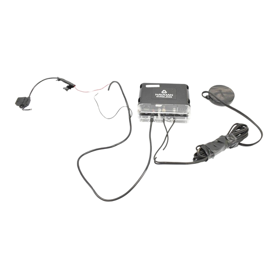
Qube3 Hardware To allow for quicker and easier installations, Navman To ensure professional installation, Navman Wireless Wireless designed an all-in-one antenna system that provides an install hardware kit for all new Qube includes both GPS and cellular components built into systems. - Page 7 Qube3 Hardware Qube3 Box Contents: Mounting Tabs Mounting Tabs 2-piece Anti-Tamper Cover Tamper Switch T-10S Security Screws (3 pcs) Diagnostic LED’s Green – Power (On/Off/Sleep) Orange – GPS (Fix/No Fix) Red – Cell (Online/Offline) 4 Mounting Screws 6-pin ConEx GPS (SMA)
- Page 8 Qube3 Hardware: Tamper Cover 2 Piece Anti-Tamper Cover Upper Tamper Cover T-10S Security Screws Lower Tamper Cover T-10S Torx Screwdriver Required 8 | Confidential...
- Page 9 Qube3 Hardware: Power Harness • RED wire – Uninterrupted Power Source (3A fuse) Red* - Constant +12/24V • PINK wire – Primary Ignition /Switched Source (3A fuse) Pink* - Ignition • BLACK wire – Chassis Ground Black - Ground *These connections must be fused (3A)
- Page 10 Qube3 Hardware: Shipping Plug Yellow Shipping Plug Internal Back-Up Battery The Yellow Shipping Plug is inserted into the Serial Data Port prior to shipping the device. This disables the internal back-up battery during shipping and prevents any cellular signal transmissions while in transit.
-
Page 11: Identifying Correct Wires
Identifying Correct Wires 1. Remove any interior/under dash trim necessary to gain access to vehicle’s wiring as well as all areas where interconnecting wire harnesses will need to be located. 2. Attach fuse holders to the Constant and Ignition wires of the Qube’s harness. 3. - Page 12 Identifying Correct Wires Vehicle’s Constant Power wire The correct wire will have battery voltage +12V (or +24V) present at all times, even when the ignition key is in off position or removed. Connect Qube’s red wire here. Vehicle’s Ignition wire The correct wire will have +12V (or +24V) present only when -- the key is in ON position, during cranking and while motor is running.
-
Page 13: Poke & Wrap" Solder-Less Connections
“Poke & Wrap” Solder-less Connections Whenever connecting wires inside the cab, the recommended method soldering. alternative, a “Poke & Wrap” method for solder- less connections can be used. Strip. Use wire strippers to pull back at least ¾ inch insulation from the vehicle’s source wire. Next, strip back approximately 1”... -
Page 14: Chassis Ground Connection
Chassis Ground Connection • Connect the Qube’s Ground wire (black) to vehicle’s chassis. • For a solid connection, use a ring tongue terminal connector, star washer and a self-tapping screw • Do not ground under existing bolts that hold brackets or panels in place. 14 | Confidential... -
Page 15: Mounting The Antenna
Mounting the Antenna GPS/Cell Combination Antenna *View from under the dash • Exposed install: Using the supplied double-sided tape pad, mount the antenna to the bottom corner of the windshield. Make sure the correct side of antenna is facing out, into the sky. •... -
Page 16: Mobile Data Terminal: M-Nav800
Mobile Data Terminal: M-Nav800 Suction Mount Cradle Power Adaptor Qube3 Power/Data Cable M-Nav800 Route the M-Nav800 Power/Data cable from the Qube to the top of dashboard, where M-Nav800 will be mounted. Use the supplied suction cup mount or the optional dash mount bracket to secure the device in place. - Page 17 Mobile Data Terminal: M-Nav800 4 Screws 2 Screws Install Zip Tie In-Line Power Adaptor Optional: 2 screws for permanent mount 17 | Confidential...
-
Page 18: Conex Sensor Monitoring
ConEx Sensor Monitoring Qube3 Optional 6-pin Harness: Yellow – Multi IN-1 Green – Digital I/O-2 Blue – Digital IN-3 Purple – Digital IN-4 Black - GND Out Reference White - +3V Out Reference • Qubes are capable of monitoring multiple vehicle sensors/switches thru ConEx multi function inputs. - Page 19 ConEx Sensor Monitoring (cont.) Digital Inputs: Positive Trigger and Reverse Polarity Circuits Locate and connect directly to the trigger wire. +12V Dome Light Door Pin (+) Yellow – Multi IN-1 Digital Inputs: Negative Trigger Circuits Locate the trigger wire. Install a standard SPDT relay to convert from a negative to a positive trigger. Door Pin (-) Yellow –...
- Page 20 ConEx Sensor Monitoring (cont.) Digital Output ConEx Digital I/O -2 (green wire) can be configured as an output thru OnlineAVL2. This output will pull low with a maximum current of 250mA when activated. Standard automotive relay is required for most applications.
-
Page 21: Qube Power Up Procedure
Qube Power Up Procedure When the installation is complete, perform the following steps in the order they are listed to bring the device online promptly 1. Ensure the vehicle is outside and has clear view of sky 2. Attach both antenna cables to the Qube, 3. - Page 22 Completing the Installation: Tamper-Evident Seal “Poke and Wrap” Ground Screw Fuse Holders Apply Tamper-Evident Seal paste (Torque-Seal or inspector’s lacquer) to all “Poke and Wrap” connections, fuse holders and the ground screw. Once applied it sticks to the surface and dries hard over 24 hours. Once hard it will crack on removal making the tampering obvious.
-
Page 23: Completing The Installation
Mount the Qube to an existing wire harness with strong zip-ties or to sheet metal using screws. Position the Qube with the LEDs facing down (LEDs visible for troubleshooting and Qube3 protection from water ingress). • Complete the installation by securing all wires with zip-ties, away from any moving parts or sharp metal edges. -
Page 24: Live Test Using Technician Service Portal
Live Test with Technician Service Portal 24 | Confidential... - Page 25 Technician Service Portal (TSP) • To ensure all Navman Wireless hardware is installed and functioning properly all new installations and field technician repairs must be verified through our web-based electronic system: Technician Service Portal (TSP) • TSP is a website designed for access with mobile devices in the field, specifically a smart phone or tablet.
- Page 26 (phone/tablet/computer) at http://install.navmanwireless.com – Enter Username (your email) and Password and click the “Sign In” button • Username and Password is available to all certified installation partners • To add a new account please contact Navman Wireless installation support at: us.dispatch@navmanwireless.com...
- Page 27 Qube • Press the “Start Tests” Button • Trouble: If the serial number is not available in the drop-down list, the Qube hasn’t been loaded into the Technician’s account. Contact Navman Technical Support (866)527-9896.
- Page 28 Technician Service Portal (TSP) Device Verification • The Live Test system must verify communication with the Qube To continue, 3 LEDs (Power/GPS/Cell) on the Qube must be lit solid Turn the Ignition “ON” Turn the Ignition “OFF” Press “NEXT” – Trouble: Allow the Qube to fully power up and establish a cellular connection prior to starting the test (approximately 3 minutes after initial power up)
- Page 29 Technician Service Portal (TSP) If Verification Fails • Verification will fail if: – The incorrect serial number is entered – The ignition is in the “ON” position – The Qube does not have a cellular connection (red LED) • Use the “Retry” button after inspecting the LEDs and verifying the ignition status •...
- Page 30 Technician Service Portal (TSP) MNav/MDT Message Testing • When installing an M-Nav or MDT make sure the serial number is added at the beginning of the test (alongside the Qube serial number) • The system will require the technician to enter a code on both the M-Nav/MDT and through the Test system to verify 2-way communication...
- Page 31 • Follow the instructions on the screen to complete each test as required – Important: Navman Wireless requires the ignition (Pink) wire to be connected to a true ignition source. The source wire must have power in the “ON/Crank/RUN” key positions. Do...
- Page 32 Technician Service Portal (TSP) Skipping Tests • In cases where a test cannot be completed or will not pass the technician can choose to “Skip” the test • When skipping a test the technician must provide an explanation for skipping –...
- Page 33 Technician Service Portal (TSP) Vehicle Data Entry • The system will prompt the technician to enter vehicle information, all fields must be completed with as much information as possible – Vehicle Number will be the “ Vehicle Display Name” in Online AVL2 –...
- Page 34 Technician Service Portal (TSP) Installation Data • Details about the installation must be entered, please give good descriptions of the hardware installation locations • Please add the wire color/code for the vehicle wires that feed the Qube power supply...
- Page 35 Technician Service Portal (TSP) Test Results • After completing the test the system will indicate a successful test and allow the technician to “Start a new test” • Upon completing a test where sections of the test failed or were skipped will be noted with a red “X”...
- Page 36 Live Test with OnlineAVL2 36 | Confidential...
-
Page 37: Live Test Using Onlineavl2
Live Test using OnlineAVL2 Verify vehicle is outside and has clear view of sky for the Live Test. Access vehicle properties in Online AVL2 and rename the Qube’s Display Name you’ve just installed from generic to customer specific asset name/number. While in vehicle properties, record odometer mileage into the maintenance window. - Page 38 Live Test using Online AVL2 (cont.) Send Message Button Satellites Column ConEx Sensor Activity Installation Power Up Events 38 | Confidential...
-
Page 39: Troubleshooting Section
Troubleshooting Section 39 | Confidential... - Page 40 Troubleshooting Qube Installation shipping plug can be used Cold Reset Qube3 1. Verify both antenna connectors are attached (perform this procedure with antennas connected) 2. Insert yellow shipping plug into RJ45 Data port (unplug any other device from RJ45 Data port) 3.
- Page 41 Qube’s power wiring, including the main harness, fuses and fuse holders. If the spare Qube is not available, remove the original Qube from vehicle for replacement. 8. When all above fails, contact Navman Support at 866-527-9896 to continue with troubleshooting and replacement hardware. Please, have device’s serial number and brief description of issue.
- Page 42 Cell LED is not on, remove the original Qube from vehicle for replacement. 15. When all above fails, contact Navman Support at 866-527-9896 to continue with troubleshooting and replacement hardware. Please, have device’s serial number and brief description of issue.
- Page 43 If the orange GPS LED is not on at this point, remove the original Qube from vehicle for replacement. 11. When all above fails, contact Navman Support at 866-527-9896 to continue with troubleshooting and replacement hardware. Please, have device’s serial number and brief description of issue.
- Page 44 Troubleshooting Wiring Symptom: Qube is reporting to AVL2 but displays “Power up” and “Ignition On” icons. This condition is most likely caused by improper connections of the Qube’s power wires to vehicle circuits. The installer may have connected the constant +12V wire or the ground wire from the Qube’s power harness to a switched source in vehicle. In some cases, the constant +12V and the ignition wires are connected in reverse.
- Page 45 Hardware Swap Procedure: determining faulty piece of hardware 1. Verify that the Qube is functional and reporting to Online AVL2. 2. Call Navman Support to have the Qube’s serial port set to communicate with the M-Nav. If problem persists, proceed to next step.
-
Page 46: Dimensions And Specifications
Dimensions and Specifications: Qube3 Physical • Weight: 300 g • Packed Weight (Gift Box): 540 g • Case Material: Bayer KU2 1514 ABS/Polycarbonate blend • Tamper Cover: Polycarbonate Power Supply • Nominal operating voltage: 12 or 24V vehicle supplies • Minimum operating voltage: 9 V •... -
Page 47: Technical Support
Technical Support Department Hours: Monday – Friday 7am – 7pm (Central Time) e-mail: us.support@navmanwireless.com Toll Free Phone # 866-527-9896 Local Phone # 847-832-6950 47 | Confidential... -
Page 48: Global Positioning System (Gps)
Global Positioning System (GPS) Global Positioning System (GPS) is a space-based global navigation satellite system (GNSS) that provides reliable location and time information in all weather and at all times and anywhere on or near the Earth. As a national resource, it is maintained by the United States government and is freely accessible by anyone with a GPS receiver. -
Page 49: Disclaimer
Disclaimer Although Navman Wireless’s goods, services, and software can be useful as a part of a logistics and/or property management program, Navman Wireless makes no warranty whatsoever that its goods, services, or software will prevent or mitigate any theft, misappropriation, injury, delay, or other adverse condition. Navman Wireless’s goods, services, and software are not designed,... - Page 50 2701 Patriot Blvd. Suite 150 Glenview, IL 60026 USA T: +1.866.527.9896 F: +1.847.832.2475 navmanwireless.com...