Agilent Technologies 7000 Series Operating Manual
Hide thumbs
Also See for 7000 Series:
- Service manual (120 pages) ,
- User manual (428 pages) ,
- Operating manual (216 pages)
Table of Contents
Advertisement
Advertisement
Table of Contents

Related Manuals for Agilent Technologies 7000 Series


Summary of Contents for Agilent Technologies 7000 Series
- Page 1 Agilent 7000/7010 Series Triple Quadrupole Operating Manual...
- Page 2 Notices Warranty © Agilent Technologies, Inc. 2019 WAR N IN G No part of this manual may be repro- The material contained in this docu- duced in any form or by any means ment is provided “as is,” and is subject...
-
Page 3: About This Manual
About This Manual This manual contains information for operating and maintaining the Agilent 7000/7010 Series Triple Quad (TQ) Mass Spectrometer (MS) system. “Introduction” Chapter 1 describes general information about the 7000/7010 Series TQ GC/MS, including a hardware description, general safety warnings, and hydrogen safety information. -
Page 4: Hardware User Information
Hardware User Information Accompanying your hardware and software is a comprehensive collection of manuals, videos, user applications, and method development tools. These are located on the: • Agilent GC and GC/MS User Manuals and Tools DVD set • Agilent GC/MS Software Information and Manuals memory stick To Install Your Hardware Library Insert the disk into your DVD drive and follow the prompts. -
Page 5: Table Of Contents
Contents About This Manual Hardware User Information Introduction Abbreviations Used The 7000/7010 Series TQ GC/MS Physical description Vacuum gauge 7000/7010 CI MS System 7000/7010 Series Triple Quadrupole Hardware Description Important Safety Warnings Many internal parts of the MS carry dangerous voltages Electrostatic discharge is a threat to MS electronics Many parts are dangerously hot... - Page 6 Cleaning/Recycling the Product Accidental Liquid Spill Moving or Storing the MS Installing 8890 GC Columns Columns Conditioning columns Conditioning ferrules Tips and hints To Install a Capillary Column in a Split/Splitless Inlet To Condition a Capillary Column To Install a Capillary Column in the GC/MS Interface Using the Self-Tightening Column Nut To Install a Capillary Column in the GC/MS Interface Using a Standard Column Nut...
- Page 7 To Install the GC/MS Interface Tip Seal The GC/MS Interface for a 9000 GC Installing 7890 GC Columns Columns Conditioning columns Conditioning ferrules Tips and hints To Install a Capillary Column in a Split/Splitless Inlet To Condition a Capillary Column To Install a Capillary Column in the GC/MS Interface Using the Self-Tightening Column Nut To Install a Capillary Column in the GC/MS Interface Using a...
- Page 8 Controlling CC Flow Controlling JetClean Hydrogen Flow Venting the MS High Vacuum Pressure in EI Mode To Set Monitors for MS Temperature and Vacuum Status To Set the MS Analyzer’s Temperatures To Set the GC/MS Interface Temperature from MassHunter To Configure CC Gas To Set the Mode for the Optional JetClean System To Set the JetClean Parameters for the Clean Only Mode...
- Page 9 Analyzer vacuum with reagent gas flowing Other Reagent Gases Isobutane CI Carbon Dioxide CI CI Autotune The CI Flow Control Module To Operate the Reagent Gas Flow Control Module To Set a Reagent Gas Flow To Perform a CI Autotune To Pumpdown and Switch from EI to CI Mode General Maintenance Before Starting...
- Page 10 To Remove the EI HES To Connect or Disconnect Wiring to the EI HES To Remove the EI XTR Source To Connect or Disconnect Wiring to the EI XTR Source To Disassemble the EI HES To Disassemble the EI XTR Source To Clean the EI HES To Clean the EI XTR Source To Assemble the EI HES...
- Page 11 To Switch from the CI Source to the EI XTR Source To Connect or Disconnect 7010 Series CI Source Wiring To Connect or Disconnect 7000 Series CI Source Wiring To Switch from the CI Source to an EI XTR Source...
- Page 12 To Install a CI Source Filament 7000/7010 Series TQ GC/MS Operating Manual...
-
Page 13: Introduction
Introduction Abbreviations Used 14 The 7000/7010 Series TQ GC/MS 16 7000/7010 Series Triple Quadrupole Hardware Description 18 Important Safety Warnings 19 Hydrogen Safety 21 Safety and Regulatory Certifications 24 Intended Use 28 Cleaning/Recycling the Product 28 Accidental Liquid Spill 28 Moving or Storing the MS 28 This section provides general information about the 7000/7010 Series Triple Quad (TQ) Gas Chromatograph (GC) / Mass Spectrometer (MS), including a hardware... -
Page 14: Abbreviations Used
Introduction Abbreviations Used Abbreviations Used The abbreviations in Table 1 are used in discussing this product. They are collected here for convenience. Table 1 Abbreviations Abbreviation Definition Alternating current Automatic liquid sampler Collision cell Chemical ionization Collision induced dissociation Ceramic source board Direct current Electron impact Electron multiplier (detector) - Page 15 Introduction Abbreviations Used Table 1 Abbreviations (continued) Abbreviation Definition Front quadrupole Rear quadrupole Negative chemical ionization Octafluoronaphthalene (sample) Positive chemical ionization PFDTD Perfluoro-5,8-dimethyl-3,6,9-trioxydodecane (calibrant) PFTBA Perfluorotributylamine (calibrant) Quad Quadrupole mass filter Radio frequency RFPA Radio frequency power amplifier Torr Unit of pressure, 1 mm Hg Triple Quad (quadrupole) Turbo Split flow turbomolecular vacuum pump...
-
Page 16: The 7000/7010 Series Tq Gc/Ms
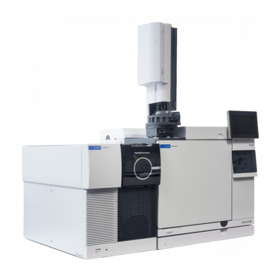
Introduction The 7000/7010 Series TQ GC/MS The 7000/7010 Series TQ GC/MS The 7000/7010 Series TQ GC/MS is a standalone capillary GC detector for use with the Agilent 8890, 9000, or 7890 GCs. (See Figure 1 on page 18.) The TQ GC/MS features: •... -
Page 17: Vacuum Gauge
Introduction Vacuum gauge Vacuum gauge The 7000/7010 Series TQ GC/MS is equipped with two ion vacuum gauges. The Agilent MassHunter GC/MS Acquisition software can be used to read the pressure (high vacuum) in the vacuum manifold and at the turbomolecular vacuum pump discharge. -
Page 18: 7000/7010 Series Triple Quadrupole Hardware Description
Introduction 7000/7010 Series Triple Quadrupole Hardware Description 7000/7010 Series Triple Quadrupole Hardware Description 8890 GC 7000/7010 Series TQ MS Drawer MS power switch GC power switch System status LED Figure 1. 7000/7010 Series TQ GC/MS system with 8890 GC 7000/7010 Series TQ GC/MS Operating Manual... -
Page 19: Important Safety Warnings
Introduction Important Safety Warnings Important Safety Warnings There are several important safety notices to always keep in mind when using the MS. Many internal parts of the MS carry dangerous voltages If the MS is connected to a power source, even if the power switch is off, potentially dangerous voltages exist on: •... -
Page 20: Many Parts Are Dangerously Hot
Introduction Many parts are dangerously hot Many parts are dangerously hot Many parts of the GC/MS operate at temperatures high enough to cause serious burns. These parts include, but are not limited to the: • Inlet • Oven and its contents •... -
Page 21: Hydrogen Safety
Introduction Hydrogen Safety Hydrogen Safety The use of hydrogen as a GC carrier gas, detector fuel gas, or in the optional WAR N IN G JetClean system, is potentially dangerous. When using hydrogen (H ) as the carrier gas or fuel gas, be aware that WAR N IN G hydrogen gas can flow into the GC oven and create an explosion hazard. -
Page 22: Hydrogen Accumulation In An Ms
Introduction Hydrogen accumulation in an MS • Accumulation of hydrogen in the GC oven and subsequent combustion. See your GC documentation and the label on the top edge of the GC oven door. • Accumulation of hydrogen in the MS and subsequent combustion Hydrogen accumulation in an MS The MS cannot detect leaks in inlet or detector gas streams. -
Page 23: Precautions
Introduction Precautions Once hydrogen has accumulated in a MS, extreme caution must be used when WAR N IN G removing it. Incorrect startup of a MS filled with hydrogen can cause an explosion. After a power failure, the MS may start up and begin the pumpdown process WAR N IN G by itself. -
Page 24: Safety And Regulatory Certifications
Introduction Safety and Regulatory Certifications Operating precautions • Turn off the hydrogen at its source every time you shut down the GC or MS. • Do not use hydrogen as a CC gas. • Turn off the hydrogen at its source every time you vent the MS. (Do not heat the capillary column without carrier gas flow.) •... -
Page 25: Information
이 기기는 업무용 (A 급 ) 전자파적합기기로서 판 매자 또는 사용자는 이 점을 주 의하시기 바라 며 , 가정외의 지역에서 사용하는 것을 목적으 로 합니다 . Information The Agilent Technologies 7000/7010 Series TQ GC/MS meets the following IEC classifications: Equipment Class I, Laboratory Equipment, Installation Category II, and Pollution Degree 2. -
Page 26: Symbols
Failure to comply with these precautions violates safety standards of design and the intended use of the instrument. Agilent Technologies assumes no liability for the customer’s failure to comply with these requirements. -
Page 27: Sound Emission Declaration
• Ensure that all peripheral devices are also certified. • Ensure that appropriate cables are used to connect the device to peripheral equipment. • Consult your equipment dealer, Agilent Technologies, or an experienced technician for assistance. Changes or modifications not expressly approved by Agilent Technologies could void the user’s authority to operate the equipment. -
Page 28: Intended Use
Introduction Intended Use Intended Use Agilent products must only be used in the manner described in the Agilent product user guides. Any other use may result in damage to the product or personal injury. Agilent is not responsible for any damages caused, in whole or in part, by improper use of the products, unauthorized alterations, adjustments or modifications to the products, failure to comply with procedures in Agilent product user guides, or use of the products in violation of applicable laws, rules... -
Page 29: Installing 8890 Gc Columns
Installing 8890 GC Columns Columns 30 To Install a Capillary Column in a Split/Splitless Inlet 32 To Condition a Capillary Column 35 To Install a Capillary Column in the GC/MS Interface Using the Self-Tightening Column Nut 37 To Install a Capillary Column in the GC/MS Interface Using a Standard Column Nut 42 To Install the GC/MS Interface Tip Seal 45 The GC/MS Interface for an 8890 Series GC 47... -
Page 30: Columns
Installing 8890 GC Columns Columns Columns Many types of GC columns can be used with the MS, but there are some restrictions. During tuning or data acquisition, the rate of column flow into the MS should not exceed the maximum recommended flow. Therefore, there are limits to column length and flow. -
Page 31: Conditioning Columns
Installing 8890 GC Columns Conditioning columns Conditioning columns Conditioning a column before it is connected to the GC/MS interface is essential. A small portion of the capillary column stationary phase is often carried away by the carrier gas. This is called column bleed. Column bleed deposits traces of the stationary phase in the MS ion source. -
Page 32: To Install A Capillary Column In A Split/Splitless Inlet
Installing 8890 GC Columns To Install a Capillary Column in a Split/Splitless Inlet To Install a Capillary Column in a Split/Splitless Inlet Materials needed • Gloves, clean, lint-free (Large 8650-0030) (Small 8650-0029) • Metric ruler • Wrench, open-end, 1/4-inch and 5/16-inch (8710-0510) •... - Page 33 Installing 8890 GC Columns To Install a Capillary Column in a Split/Splitless Inlet Always wear clean gloves while handling any parts that go inside the GC or C AU T I O N analyzer chambers. 2 Wearing clean gloves, slide a septum, column nut, and conditioned ferrule onto the free end of the column.
- Page 34 Installing 8890 GC Columns To Install a Capillary Column in a Split/Splitless Inlet 10 Adjust the column position so the septum is even with the bottom of the column nut. Never use a wrench to tighten a self-tightening nut. This may result in damage C AU T I O N to the nut or instrument....
-
Page 35: To Condition A Capillary Column
Installing 8890 GC Columns To Condition a Capillary Column To Condition a Capillary Column Materials needed • Carrier gas, (99.9995% pure or better) • Wrench, open-end, 1/4-inch and 5/16-inch (8710-0510) Do not condition your capillary column with hydrogen. Hydrogen accumulation WAR N IN G in the GC oven can result in an explosion. - Page 36 Installing 8890 GC Columns To Condition a Capillary Column See also For more information about installing a capillary column, refer to Optimizing Splitless Injections on Your GC for High Performance MS Analysis, Agilent Technologies publication number 5988-9944EN. 7000/7010 Series TQ GC/MS Operating Manual...
-
Page 37: To Install A Capillary Column In The Gc/Ms Interface Using The Self-Tightening Column Nut
Installing 8890 GC Columns To Install a Capillary Column in the GC/MS Interface Using the Self-Tightening Column Nut To Install a Capillary Column in the GC/MS Interface Using the Self-Tightening Column This procedure is for the installation of a capillary column directly into the analyzer using the Agilent recommended self-tightening column nut. - Page 38 Installing 8890 GC Columns To Install a Capillary Column in the GC/MS Interface Using the Self-Tightening Column Nut Procedure Always wear clean gloves while handling any parts that go inside the GC or the C AU T I O N analyzer chambers.
- Page 39 Installing 8890 GC Columns To Install a Capillary Column in the GC/MS Interface Using the Self-Tightening Column Nut 10 Adjust the column so it extends this specified distance from the end of the transfer line. (See Figure 4 Figure 5 on page 39.)...
- Page 40 Installing 8890 GC Columns To Install a Capillary Column in the GC/MS Interface Using the Self-Tightening Column Nut 11 Hand-tighten the nut. (See Figure 6.) Ensure the position of the column does not change as you tighten the nut. 12 Tighten the nut in the clockwise direction. Continue to tighten until you feel the ferrule grip the column.
- Page 41 16 You can align the ion source and interface tip seal by wiggling the side plate on its hinge. If the door still will not close, contact your Agilent Technologies service representative. 17 Close the front analyzer chamber. (See “To Close the Front Analyzer...
-
Page 42: To Install A Capillary Column In The Gc/Ms Interface Using A Standard Column Nut
Installing 8890 GC Columns To Install a Capillary Column in the GC/MS Interface Using a Standard Column Nut To Install a Capillary Column in the GC/MS Interface Using a Standard Column Nut This procedure is for the installation of a capillary column directly into the analyzer. - Page 43 Installing 8890 GC Columns To Install a Capillary Column in the GC/MS Interface Using a Standard Column Nut Procedure Always wear clean gloves while handling any parts that go inside the GC or the C AU T I O N analyzer chambers.
- Page 44 16 You can align the ion source and interface tip seal by wiggling the side plate on its hinge. If the door still will not close, contact your Agilent Technologies service representative. 17 Close the front analyzer chamber. (See “To Close the Front Analyzer...
-
Page 45: To Install The Gc/Ms Interface Tip Seal
Installing 8890 GC Columns To Install the GC/MS Interface Tip Seal To Install the GC/MS Interface Tip Seal Materials needed • Interface tip seal (G3870-20542) • Tip seal spring (G7005-20024) • Knurled tip seal retainer (G3870-20547) • Gloves, clean, lint-free (Large 8650-0030) (Small 8650-0029) The interface tip seal must be in place for the CI source, the EI XTR source, and HES. - Page 46 5 You can align the analyzer and interface by wiggling the side plate on its hinge. If the analyzer still will not close, contact your Agilent Technologies service representative.
-
Page 47: The Gc/Ms Interface For An 8890 Series Gc
Installing 8890 GC Columns The GC/MS Interface for an 8890 Series GC The GC/MS Interface for an 8890 Series GC The GC/MS interface is a heated conduit into the MS for the capillary column. (See Figure 8.) It is bolted onto the right side of the analyzer chamber, with an O-ring seal and has a protective cover which should be left in place. - Page 48 Installing 8890 GC Columns The GC/MS Interface for an 8890 Series GC When operating in CI mode, reagent gas is plumbed into the interface. The interface assembly extends into the ionization chamber. A spring-loaded seal helps to keep reagent gases inside the source. The reagent gas enters the interface body and mixes with carrier gas and sample in the ion source.
-
Page 49: Installing Intuvo 9000 Gc Column
Installing Intuvo 9000 GC Column Columns 50 To Replace an Intuvo GC Column 53 To Replace an Intuvo 9000 GC Gasket 57 To Install a Column Guard or Jumper Chip 58 To Replace the 9000 GC/MS Tail 62 To Condition an Intuvo Capillary Column 66 To Install the GC/MS Interface Tip Seal 68 The GC/MS Interface for a 9000 GC 70 This chapter shows you how to install an Agilent Intuvo column, connect a flow... -
Page 50: Columns
Installing Intuvo 9000 GC Column Columns Columns Many types of Intuvo 9000 GC columns can be used with the MS, but there are some restrictions. During tuning or data acquisition, the rate of column flow into the MS should not exceed the maximum recommended flow. -
Page 51: Conditioning Intuvo Columns
Installing Intuvo 9000 GC Column Conditioning Intuvo columns Conditioning Intuvo columns An Intuvo column is checked for column bleed as part of the manufacturing process. This eliminates the need for conditioning of an Intuvo column before it is connected to the GC/MS interface. When first connected to the GC/MS interface, Agilent recommends running a short column conditioning procedure. -
Page 52: Handling The Intuvo 9000 Gc Column And Bus Components
Installing Intuvo 9000 GC Column Handling the Intuvo 9000 GC Column and Bus Components Handling the Intuvo 9000 GC Column and Bus Components The Agilent Intuvo 9000 Gas Chromatograph (Intuvo 9000 GC) does not use traditional ferrules and nuts for most column and flow path seals. In a traditional gas chromatography connection, the seal is made by deforming a soft ferrule around the periphery of a column or tube, with a second seal made between the ferrule and the fitting. -
Page 53: To Replace An Intuvo Gc Column
Installing Intuvo 9000 GC Column To Replace an Intuvo GC Column To Replace an Intuvo GC Column This procedure applies to GCs with a single column. For a 2 column replacement see the Agilent Intuvo 9000 Gas Chromatograph Maintaining Your GC manual. Materials needed •... - Page 54 Installing Intuvo 9000 GC Column To Replace an Intuvo GC Column Bus door Oven door Front door Intuvo torque driver Figure 9. 9000 GC front door, bus door, oven door, and Intuvo torque driver 5 Open the bus door and remove it by lifting the door vertically off its hinge pins.
- Page 55 Installing Intuvo 9000 GC Column To Replace an Intuvo GC Column Click and run connectors Compression bolts Column clamps Retainer ring SmartID key Figure 10. 9000 GC column and related parts 8 Unplug the column SmartID key from the lower USB port. 9 Using the Intuvo torque driver, remove the two compression bolts that seal the column's click and run connectors to the bus and store for later use.
- Page 56 Installing Intuvo 9000 GC Column To Replace an Intuvo GC Column 12 Verify that all Intuvo gaskets in the flow path are rated for the maximum column temperature expected with your method. Replace any gaskets that have a lower temperature rating with one that has a temperature rating that is compatible with your method.
-
Page 57: To Replace An Intuvo 9000 Gc Gasket
Installing Intuvo 9000 GC Column To Replace an Intuvo 9000 GC Gasket To Replace an Intuvo 9000 GC Gasket This procedure assumes you have already removed the column, 9000 GC/MS Tail, or other part that sits on top of the gasket and that the instrument components are below 40 °C. -
Page 58: To Install A Column Guard Or Jumper Chip
Installing Intuvo 9000 GC Column To Install a Column Guard or Jumper Chip To Install a Column Guard or Jumper Chip The column Guard Chip and the Jumper Chip are both single-use, consumable parts. Installation deforms part of the Chip to make a good seal, so that a mis-installed Chip cannot be re- used. - Page 59 Installing Intuvo 9000 GC Column To Install a Column Guard or Jumper Chip 3 Wait until the GC reaches the ready state indicating the components are cooled below 40 °C and the instrument is vented before continuing the steps in this procedure. 4 If you are using hydrogen or other flammable gas as a carrier gas or for the JetClean system, close the manual gas supply valve to the instrument before turning off the MS power.
- Page 60 Installing Intuvo 9000 GC Column To Install a Column Guard or Jumper Chip Guard chip compression bolt Guard chip Inlet base Guard chip screw Guard chip heater Figure 12. Guard chip and related parts 10 Use a 7/16- inch open-end wrench to loosen the Guard Chip screw at the base of the inlet.
- Page 61 Installing Intuvo 9000 GC Column To Install a Column Guard or Jumper Chip 20 Tighten the Guard Chip compression bolt using the provided torque driver until you hear one click. 21 Install the inlet cover. 22 Install the bus door on its hinges and close it. 23 Close the GC front door.
-
Page 62: To Replace The 9000 Gc/Ms Tail
Installing Intuvo 9000 GC Column To Replace the 9000 GC/MS Tail To Replace the 9000 GC/MS Tail This procedure is necessary if you are switching to a source that requires a different 9000 GC/MS Tail, replacing a leaking gasket or a contaminated 9000 GC/MS Tail, or separating the 9000 GC from the MS. - Page 63 Installing Intuvo 9000 GC Column To Replace the 9000 GC/MS Tail 5 Unscrew the knurled tip seal retainer from the tip seal holder and remove the tip seal, spring, and knurled tip seal retainer from the GC/MS interface. (See “GC/MS interface tip seal” on page 69.) 6 Ensure the MS is properly aligned with the GC.
- Page 64 Installing Intuvo 9000 GC Column To Replace the 9000 GC/MS Tail Ferrule release hole Transfer line Bus click and run connection Figure 14. MS tail heater assembly clamp open with 9000 GC/MS Tail removed Ferrule and nut Exit in ion source Click and run connection Figure 15.
- Page 65 26 You can align the ion source and interface tip seal by wiggling the side plate on its hinge. If the door still will not close, contact your Agilent Technologies service representative. 27 Close the front analyzer chamber. (See “To Close the Front Analyzer...
-
Page 66: To Condition An Intuvo Capillary Column
Installing Intuvo 9000 GC Column To Condition an Intuvo Capillary Column To Condition an Intuvo Capillary Column Materials needed • Carrier gas, (99.9995% pure or better) • Gloves, clean, lint-free (Large 8650-0030) (Small 8650-0029) • Tweezers (8710-2460) • Intuvo torque driver stored on oven door (5190-9571) •... - Page 67 Installing Intuvo 9000 GC Column To Condition an Intuvo Capillary Column 7 Hold at the maximum temperature for 30 minutes. The column is conditioned and ready to be used with your method. 7000/7010 Series TQ GC/MS Operating Manual...
-
Page 68: To Install The Gc/Ms Interface Tip Seal
Installing Intuvo 9000 GC Column To Install the GC/MS Interface Tip Seal To Install the GC/MS Interface Tip Seal Materials needed • Interface tip seal (G3870-20542) • Tip seal spring (G7005-20024) • Knurled tip seal retainer (G3870-20547) • Gloves, clean, lint-free (Large 8650-0030) (Small 8650-0029) The interface tip seal must be in place for the CI source, the EI XTR source, and HES. - Page 69 5 You can align the analyzer and interface by wiggling the side plate on its hinge. If the analyzer still will not close, contact your Agilent Technologies service representative.
-
Page 70: The Gc/Ms Interface For A 9000 Gc
Installing Intuvo 9000 GC Column The GC/MS Interface for a 9000 GC The GC/MS Interface for a 9000 GC The GC/MS Interface is a heated conduit into the MS for maintaining MS vacuum and a suitable column effluent temperature. (See Figure 17.) The GC/MS Interface is bolted onto the right side of the analyzer chamber, with an O-ring seal... - Page 71 Installing Intuvo 9000 GC Column The GC/MS Interface for a 9000 GC The 9000 GC/MS Tail is heated by an electric cartridge heater. The heater is powered and controlled by a heated zone of the 9000 GC. The 9000 GC/MS Tail temperature can be set from the Agilent MassHunter GC/MS Acquisition software or from the GC.
- Page 72 Installing Intuvo 9000 GC Column The GC/MS Interface for a 9000 GC 7000/7010 Series TQ GC/MS Operating Manual...
-
Page 73: Installing 7890 Gc Columns
Installing 7890 GC Columns Columns 74 To Install a Capillary Column in a Split/Splitless Inlet 76 To Condition a Capillary Column 79 To Install a Capillary Column in the GC/MS Interface Using the Self-Tightening Column Nut 81 To Install a Capillary Column in the GC/MS Interface Using a Standard Column Nut 86 To Install the GC/MS Interface Tip Seal 89 The GC/MS Interface for an 7890 Series GC 91... -
Page 74: Columns
Installing 7890 GC Columns Columns Columns Many types of GC columns can be used with the MS, but there are some restrictions. During tuning or data acquisition, the rate of column flow into the MS should not exceed the maximum recommended flow. Therefore, there are limits to column length and flow. -
Page 75: Conditioning Columns
Installing 7890 GC Columns Conditioning columns Conditioning columns Conditioning a column before it is connected to the GC/MS interface is essential. A small portion of the capillary column stationary phase is often carried away by the carrier gas. This is called column bleed. Column bleed deposits traces of the stationary phase in the MS ion source. -
Page 76: To Install A Capillary Column In A Split/Splitless Inlet
Installing 7890 GC Columns To Install a Capillary Column in a Split/Splitless Inlet To Install a Capillary Column in a Split/Splitless Inlet Materials needed • Gloves, clean, lint-free (Large 8650-0030) (Small 8650-0029) • Metric ruler • Wrench, open-end, 1/4-inch and 5/16-inch (8710-0510) •... - Page 77 Installing 7890 GC Columns To Install a Capillary Column in a Split/Splitless Inlet Always wear clean gloves while handling any parts that go inside the GC or C AU T I O N analyzer chambers. 2 Wearing clean gloves, slide a septum, column nut, and conditioned ferrule onto the free end of the column.
- Page 78 Installing 7890 GC Columns To Install a Capillary Column in a Split/Splitless Inlet 10 Adjust the column position so the septum is even with the bottom of the column nut. Never use a wrench to tighten a self-tightening nut. This may result in damage C AU T I O N to the nut or instrument....
-
Page 79: To Condition A Capillary Column
Installing 7890 GC Columns To Condition a Capillary Column To Condition a Capillary Column Materials needed • Carrier gas, (99.9995% pure or better) • Wrench, open-end, 1/4-inch and 5/16-inch (8710-0510) Do not condition your capillary column with hydrogen. Hydrogen accumulation WAR N IN G in the GC oven can result in an explosion. - Page 80 Installing 7890 GC Columns To Condition a Capillary Column See also For more information about installing a capillary column, refer to Optimizing Splitless Injections on Your GC for High Performance MS Analysis, Agilent Technologies publication number 5988-9944EN. 7000/7010 Series TQ GC/MS Operating Manual...
-
Page 81: To Install A Capillary Column In The Gc/Ms Interface Using The Self-Tightening Column Nut
Installing 7890 GC Columns To Install a Capillary Column in the GC/MS Interface Using the Self-Tightening Column Nut To Install a Capillary Column in the GC/MS Interface Using the Self-Tightening Column This procedure is for the installation of a capillary column directly into the analyzer using the Agilent recommended self-tightening column nut. - Page 82 Installing 7890 GC Columns To Install a Capillary Column in the GC/MS Interface Using the Self-Tightening Column Nut Procedure Always wear clean gloves while handling any parts that go inside the GC or the C AU T I O N analyzer chambers.
- Page 83 Installing 7890 GC Columns To Install a Capillary Column in the GC/MS Interface Using the Self-Tightening Column Nut 10 Adjust the column so it extends this specified distance from the end of the transfer line. (See Figure 20 Figure 21 on page 83.)...
- Page 84 Installing 7890 GC Columns To Install a Capillary Column in the GC/MS Interface Using the Self-Tightening Column Nut 11 Hand-tighten the nut. (See Figure 22.) Ensure the position of the column does not change as you tighten the nut. 12 Tighten the nut in the clockwise direction. Continue to tighten until you feel the ferrule grip the column.
- Page 85 16 You can align the ion source and interface tip seal by wiggling the side plate on its hinge. If the door still will not close, contact your Agilent Technologies service representative. 17 Close the front analyzer chamber. (See “To Close the Front Analyzer...
-
Page 86: To Install A Capillary Column In The Gc/Ms Interface Using A Standard Column Nut
Installing 7890 GC Columns To Install a Capillary Column in the GC/MS Interface Using a Standard Column Nut To Install a Capillary Column in the GC/MS Interface Using a Standard Column Nut This procedure is for the installation of a capillary column directly into the analyzer. - Page 87 Installing 7890 GC Columns To Install a Capillary Column in the GC/MS Interface Using a Standard Column Nut Procedure Always wear clean gloves while handling any parts that go inside the GC or the C AU T I O N analyzer chambers.
- Page 88 16 You can align the ion source and interface tip seal by wiggling the side plate on its hinge. If the door still will not close, contact your Agilent Technologies service representative. 17 Close the front analyzer chamber. (See “To Close the Front Analyzer...
-
Page 89: To Install The Gc/Ms Interface Tip Seal
Installing 7890 GC Columns To Install the GC/MS Interface Tip Seal To Install the GC/MS Interface Tip Seal Materials needed • Interface tip seal (G3870-20542) • Tip seal spring (G7005-20024) • Knurled tip seal retainer (G3870-20547) • Gloves, clean, lint-free (Large 8650-0030) (Small 8650-0029) The interface tip seal must be in place for the CI source, the EI XTR source, and HES. - Page 90 5 You can align the analyzer and interface by wiggling the side plate on its hinge. If the analyzer still will not close, contact your Agilent Technologies service representative.
-
Page 91: The Gc/Ms Interface For An 7890 Series Gc
Installing 7890 GC Columns The GC/MS Interface for an 7890 Series GC The GC/MS Interface for an 7890 Series GC The GC/MS interface is a heated conduit into the MS for the capillary column. (See Figure 24.) It is bolted onto the right side of the analyzer chamber, with an O-ring seal and has a protective cover which should be left in place. - Page 92 Installing 7890 GC Columns The GC/MS Interface for an 7890 Series GC When operating in CI mode, reagent gas is plumbed into the interface. The interface assembly extends into the ionization chamber. A spring-loaded seal helps to keep reagent gases inside the source. The reagent gas enters the interface body and mixes with carrier gas and sample in the ion source.
-
Page 93: To Calibrate The Column
Installing 7890 GC Columns To Calibrate the Column To Calibrate the Column Capillary columns must be calibrated prior to use with the MS. This procedure applies only to the 7890 GC. Procedure 1 Set Data Acquisition for splitless manual injection and selected ion monitoring (SIM) of m/z 28. - Page 94 Installing 7890 GC Columns To Calibrate the Column Figure 25. Calculate Column Length dialog 11 When the new column length appears, click OK to save the changes. 12 Click OK on the Calibrate Columns dialog to save the calibration. 7000/7010 Series TQ GC/MS Operating Manual...
-
Page 95: Operating In Ei Mode
Operating in EI Mode Operating the MS from the Data System 96 Set the IP Address and View TQ Parameters with the WUI 97 Before You Turn On the MS 102 Pumping Down 103 Controlling Temperatures 103 Controlling Column Flow 104 Controlling CC Flow 104 Controlling JetClean Hydrogen Flow 104 Venting the MS 105... -
Page 96: Operating The Ms From The Data System
Operating in EI Mode Operating the MS from the Data System Operating the MS from the Data System The Agilent MassHunter GC/MS Acquisition software performs tasks such as pumping down, monitoring pressures, setting temperatures, tuning, and preparing to vent. These tasks are described in this chapter. Additional information is described in the manuals and online help supplied with the MassHunter GC/MS Acquisition software. -
Page 97: Set The Ip Address And View Tq Parameters With The Wui
Operating in EI Mode Set the IP Address and View TQ Parameters with the WUI Set the IP Address and View TQ Parameters with the WUI The Web User Interface (WUI) is used by Agilent field support for setup and monitoring of the instrument. - Page 98 Operating in EI Mode To change the network settings of the TQ 3 Click Edit NetConfig, and go to Edit NetConfig (QQQ network configuration). (See Figure 27.) Figure 27. WUI Edit NetConfig 4 Enter the GC IP Address in the DCOMM Partner IP Address if your GC supports DCOMM.
-
Page 99: View The Tq Parameters
Operating in EI Mode View the TQ parameters GC/MS Instrument Configuration program. See Configure the system in the 7890A+ or 7890B GC in the GC/MS Instrument Configuration program help. 9 In the GC/MS Instrument Configuration program, edit the TQ IP address using these new parameters. - Page 100 Operating in EI Mode View the TQ parameters 3 Click Instrument Status to display the TQ turbo pump speed, zone temperatures, high vacuum pressure, TQ faults, net configuration parameters, and smart card firmware version. (See Figure 29.) Figure 29. WUI instrument status 4 When done, close the browser.
-
Page 101: Front Panel Instrument Status Led
Operating in EI Mode Front Panel Instrument Status LED Front Panel Instrument Status LED Through the front panel Instrument Status LED, the operator can view the current status of the instrument using color codes and LED On/Off timing. (See Table Table 6 Front panel Instrument Status LED codes Instrument status... -
Page 102: Before You Turn On The Ms
Operating in EI Mode Before You Turn On the MS Before You Turn On the MS Verify the following before you turn on or attempt to operate the MS. • The vent valve must be closed (the knob turned all the way clockwise). (See “To Pumpdown the MS”... -
Page 103: Pumping Down
Operating in EI Mode Pumping Down When hydrogen is used as a carrier gas or during the JetClean system acquire C AU T I O N and clean mode, do not use helium in the collision cell. Pumping Down The data system helps you pumpdown the MS. The process is primarily automated. -
Page 104: Controlling Column Flow
Operating in EI Mode Controlling Column Flow Controlling Column Flow Carrier gas flow is controlled by column inlet pressure in the GC. Set the column mode to Constant Pressure to maintain a constant inlet pressure, and the column flow will decrease as the GC oven temperature increases. With EPC and the column mode set to Constant Flow, the same column flow is maintained regardless of temperature. -
Page 105: Venting The Ms
Operating in EI Mode Venting the MS Venting the MS A program in the data system guides you through the venting process. It turns off the GC and MS heaters and the turbo pump at the correct time. It also lets you monitor temperatures in the MS, and indicates when to vent the MS. -
Page 106: High Vacuum Pressure In Ei Mode
Operating in EI Mode High Vacuum Pressure in EI Mode High Vacuum Pressure in EI Mode The largest influences on operating pressure in EI mode are the carrier gas (column) and CC gas flows. Table 7 lists typical pressures for various helium and nitrogen CC gas flows. -
Page 107: To Set Monitors For Ms Temperature And Vacuum Status
Operating in EI Mode To Set Monitors for MS Temperature and Vacuum Status To Set Monitors for MS Temperature and Vacuum Status A monitor displays the current value of a single instrument parameter. They can be added to the standard instrument control window. Monitors can be set to change color if the actual parameter varies beyond a user-determined limit from its setpoint. - Page 108 Operating in EI Mode To Set Monitors for MS Temperature and Vacuum Status 2 In the Available Monitors column, select MS High Vac and click Add to move the selection to the Selected Monitors column. 3 In the Available Monitors column, select MS 1 Heater, and click Add to move the selection to the Selected Monitors column.
-
Page 109: To Set The Ms Analyzer's Temperatures
Operating in EI Mode To Set the MS Analyzer’s Temperatures To Set the MS Analyzer’s Temperatures Setpoints for the MS ion source, front quad (MS1), rear quad (MS2), and temperatures are stored in the current tune file. When a method is loaded, the setpoints in the tune file associated with that method are downloaded automatically. - Page 110 Operating in EI Mode To Set the MS Analyzer’s Temperatures Figure 32. MS1 parameters The GC/MS interface, ion source, and the MS1 quadrupole heated zones interact. The analyzer heater may not be able to accurately control temperature if the setpoint for one zone is much different from that of an adjacent zone. The software will not allow you to exceed 200 °C for the quadrupole or 350 °C for the source.
-
Page 111: To Set The Gc/Ms Interface Temperature From Masshunter
Operating in EI Mode To Set the GC/MS Interface Temperature from MassHunter To Set the GC/MS Interface Temperature from MassHunter You can also use the GC Control panel to perform this task. Procedure 1 Select Instrument > GC Parameters from the Instrument Control panel. 2 Click the Aux Heaters icon to edit the interface temperature. -
Page 112: To Configure Cc Gas
Operating in EI Mode To Configure CC Gas To Configure CC Gas 1 Configure the use of Quench Gas and Collision Gas. (See “To Set the CC Gas Flow Rates” on page 115.) 2 Select Instrument > GC Parameters from the Instrument Control panel. 3 Click the Configuration icon, then select the Modules tab to display the screen. -
Page 113: To Set The Mode For The Optional Jetclean System
Operating in EI Mode To Set the Mode for the Optional JetClean System To Set the Mode for the Optional JetClean System 1 Click the MS Parameters icon in the Instrument Control view. 2 Click Source Cleaning from the Triple Quadrupole MS Method Editor navigation panel. -
Page 114: To Set The Jetclean Parameters For The Clean Only Mode
Operating in EI Mode To Set the JetClean Parameters for the Clean Only Mode To Set the JetClean Parameters for the Clean Only Mode 1 Click the MS Parameters icon in the Instrument Control view. 2 Select Source Cleaning from the Triple Quadrupole MS Method Editor navigation panel. -
Page 115: To Set The Cc Gas Flow Rates
Operating in EI Mode To Set the CC Gas Flow Rates To Set the CC Gas Flow Rates 1 From the Agilent MassHunter GC/MS Acquisition software Instrument Control panel, select Instrument > GC Parameters. 2 Click the Columns icon to display the control parameter entry screen for column and Aux flow modules. - Page 116 Operating in EI Mode To Set the CC Gas Flow Rates Figure 37. Setting CC gas flow rate 7000/7010 Series TQ GC/MS Operating Manual...
-
Page 117: To Autotune The Ms For Ei Mode
Operating in EI Mode To Autotune the MS for EI Mode To Autotune the MS for EI Mode The MS can be tuned using the Agilent MassHunter GC/MS Acquisition software. Procedure 1 Set the system to the same conditions (column flow and MS analyzer temperatures) that will be used for data acquisition. - Page 118 Operating in EI Mode To Autotune the MS for EI Mode Figure 38. Setting up for autotune on a system configured with CI 9 Click Autotune to start the autotune. The Status line displays the current step in the autotune process, and the plot of the tuned parameter for that step is shown in the top graph.
-
Page 119: To Open Left Side Panel For Access To The Analyzer Chambers
Operating in EI Mode To Open Left Side Panel for Access to the Analyzer Chambers To Open Left Side Panel for Access to the Analyzer Chambers The left side panel should only be opened to access the front and rear analyzer chambers or the analyzer side plates. -
Page 120: To Pumpdown The Ms
Operating in EI Mode To Pumpdown the MS To Pumpdown the MS Ensure your MS meets all the conditions listed in the introduction to this WAR N IN G chapter before starting up and pumping down the MS. Failure to do so can result in personal injury. - Page 121 Operating in EI Mode To Pumpdown the MS Vent valve knob Figure 40. Vent valve knob 4 Open the vent valve by turning it counterclockwise 45 degrees. 5 Verify that the MS power cord is plugged into a grounded building’s mains receptacle.
- Page 122 Operating in EI Mode To Pumpdown the MS 11 Select the Manual Tune tab. 12 Click Pumpdown. You are prompted if you want to load high temperature settings for the ion source and MS1 and MS2 quads. 13 Click Yes to set the source/MS1/MS2 at 230/150/150 or click No to set them at 100/100/100.
- Page 123 Operating in EI Mode To Pumpdown the MS Within 10 to 15 minutes, the turbo pump speed should be up to 80% . The C AU T I O N pump speed should eventually reach 95%. If these conditions are not met, the MS electronics will shut off the foreline pump.
-
Page 124: To Vent The Ms
Operating in EI Mode To Vent the MS To Vent the MS Agilent MassHunter GC/MS Acquisition software allows you to specify parameters in a GC method that will automate and speed up the vent process if direct communication (DCOMM) with the GC is established. You must predefine a Fast Vent method to use this option. - Page 125 Operating in EI Mode To Vent the MS 7 Remove the analyzer window cover. (See “To Open Left Side Panel for Access to the Analyzer Chambers” on page 119.) 8 Turn the vent valve knob counterclockwise only 3/4 turn or until you hear the hissing sound of air flowing into the analyzer chamber.
-
Page 126: To Set The Gc/Ms Interface Temperature From The 7890 Gc
Operating in EI Mode To Set the GC/MS Interface Temperature from the 7890 GC To Set the GC/MS Interface Temperature from the 7890 GC The interface temperature can be set directly at the GC. For the Agilent 7890 Series GC, this is usually the Aux #2 temperature. See the 7890 Series GC Advanced User Guide for details. -
Page 127: To Save A Method On The 7890 Gc
Operating in EI Mode To Save a Method on the 7890 GC To Save a Method on the 7890 GC Procedure 1 Press [Method], and scroll to the specific method number. 2 Press [Store] and [On/Yes] to store the new method using the chosen number. - Page 128 Operating in EI Mode To Save a Method on the 7890 GC 7000/7010 Series TQ GC/MS Operating Manual...
- Page 129 Operating in CI Mode Setting Up Your MS to Operate in CI Mode 130 Operating the CI MS 131 High Vacuum Pressure in CI Mode 132 Other Reagent Gases 133 CI Autotune 135 The CI Flow Control Module 137 To Operate the Reagent Gas Flow Control Module 139 To Set a Reagent Gas Flow 141 To Perform a CI Autotune 142 To Pumpdown and Switch from EI to CI Mode 144...
-
Page 130: Operating In Ci Mode
Operating in CI Mode Setting Up Your MS to Operate in CI Mode Setting Up Your MS to Operate in CI Mode Setting up your MS for operation in CI mode requires special care to avoid contamination and air leaks. •... -
Page 131: Operating The Ci Ms
Operating in CI Mode Operating the CI MS Operating the CI MS Operating your GC/MS in the CI mode is slightly more complicated than operating in the EI mode. After tuning, gas flow, source temperature, and electron energy may need to be optimized for your specific analyte. (See Table Table 9 Temperatures for CI operation... -
Page 132: High Vacuum Pressure In Ci Mode
Operating in CI Mode High Vacuum Pressure in CI Mode High Vacuum Pressure in CI Mode The largest influences on operating pressure in CI mode are the reagent and CC gas flows. Table 10 lists typical pressures for various reagent gas flows, depending upon the CC gas flowrate. -
Page 133: Other Reagent Gases
Operating in CI Mode Other Reagent Gases Other Reagent Gases This section describes the use of isobutane or ammonia as the reagent gas. You should be familiar with operating the CI-equipped 7000/7010 Series TQ GC/MS with methane reagent gas before attempting to use other reagent gases. Do not use nitrous oxide as a reagent gas. -
Page 134: Carbon Dioxide Ci
Operating in CI Mode Carbon Dioxide CI Ammonia CI Ammonia (NH ) is commonly used for CI when less fragmentation is desired in the CI spectrum. This is because the proton affinity of ammonia is higher than that of methane; hence less energy is transferred in the ionization reaction. Because many compounds of interest have insufficient proton affinities, + and then, in some ammonia CI spectra often result from the addition of NH... -
Page 135: Ci Autotune
Operating in CI Mode CI Autotune CI Autotune After the reagent gas flow is set, the lenses and electronics of the MS should be tuned. (See Table 11.) Perfluoro-5,8-dimethyl-3,6,9-trioxidodecane (PFDTD) is used as the calibrant. Instead of flooding the entire vacuum chamber, the PFDTD is introduced directly into the ionization chamber through the GC/MS interface by means of the gas flow control module. - Page 136 Operating in CI Mode CI Autotune Table 11 CI tune default settings (continued) Parameter Methane Isobutane Ammonia Front quad temp 150 °C 150 °C 150 °C 150 °C 150 °C 150 °C Rear quad temp 150 °C 150 °C 150 °C 150 °C 150 °C 150 °C...
-
Page 137: The Ci Flow Control Module
Operating in CI Mode The CI Flow Control Module The CI Flow Control Module The CI reagent gas flow control module regulates the flow of reagent gas through the GC/MS interface and into the CI source. (See Figure 43 Table 12 on page 138.) The CI option consists of the MFC, gas select valves, CI calibration valve, shutoff valve, control electronics, plumbing, tip seal assembly, and CI source. - Page 138 Operating in CI Mode The CI Flow Control Module When a CI system is installed along with a JetClean system, the MFC is shared by both systems. By design, its use is restricted to one of these systems at a time.
-
Page 139: To Operate The Reagent Gas Flow Control Module
Operating in CI Mode To Operate the Reagent Gas Flow Control Module To Operate the Reagent Gas Flow Control Module Procedure 1 In Instrument Control panel, select the MS Tune icon to display the Triple Quadrupole MS Tune window. Select the Manual Tune tab, then select the Ion Source tab to display the ion source parameters. - Page 140 Operating in CI Mode To Operate the Reagent Gas Flow Control Module 2 Use the parameters in the CI Reagent Gas Control area to control reagent gas flow. CI Gas A - Selects Methane as the reagent gas. CI Gas B - Selects the gas connected to the B inlet on the gas flow controller as the reagent gas.
-
Page 141: To Set A Reagent Gas Flow
Operating in CI Mode To Set a Reagent Gas Flow To Set a Reagent Gas Flow After the system has been switched from EI to CI mode, or vented for any other C AU T I O N reason, the MS must be baked out for at least 2 hours before tuning. Continuing with CI autotune if the MS has an air leak or large amounts of water C AU T I O N will result in severe ion source contamination. -
Page 142: To Perform A Ci Autotune
Operating in CI Mode To Perform a CI Autotune To Perform a CI Autotune If you are switching from an EI to a CI source, do not use this procedure. See “To Pumpdown and Switch from EI to CI Mode” on page 144. - Page 143 Operating in CI Mode To Perform a CI Autotune 8 Select the Tune from default settings check box if you are restarting the system after a system vent, major servicing, or a power outage. If you clear the Tune from default settings box, the Autotune process starts using previous tune values.
-
Page 144: To Pumpdown And Switch From Ei To Ci Mode
Operating in CI Mode To Pumpdown and Switch from EI to CI Mode To Pumpdown and Switch from EI to CI Mode This procedure assumes that the instrument is switching from EI to CI mode, and will be PCI tuned using methane after the system is stable. Procedure 1 Follow the instructions for the EI MS pumpdown. - Page 145 Operating in CI Mode To Pumpdown and Switch from EI to CI Mode 4 Select CI/JetClean - EI/CI system since this controller is installed for the CI control option. 5 For Channel A gas, select Methane. Click OK. 6 Click the MS Tune icon in the Instrument Control panel to display the Triple Quadrupole MS Tune window, and select the Vacuum Control tab to monitor that the pressure is decreasing.
- Page 146 Operating in CI Mode To Pumpdown and Switch from EI to CI Mode 14 Click Autotune to start the autotune. At the completion of the autotune a Tune Report is printed. 15 Review the Tune Report. If the results are acceptable, save the autotune by clicking the Files and Report tab, then click Save.
-
Page 147: General Maintenance
General Maintenance Before Starting 148 Maintaining the Vacuum System 153 Maintaining the Analyzer 154 To Open the Front Analyzer Chamber 156 To Remove the EI HES 159 To Connect or Disconnect Wiring to the EI HES 161 To Remove the EI XTR Source 162 To Connect or Disconnect Wiring to the EI XTR Source 164 To Disassemble the EI HES 165 To Disassemble the EI XTR Source 168... -
Page 148: Before Starting
General Maintenance Before Starting Before Starting You can perform much of the maintenance required by your MS. For your safety, read all of the information in this introduction before performing any maintenance tasks. Scheduled maintenance Performing common maintenance tasks when scheduled can reduce operating problems, prolong system life, and reduce overall operating costs. -
Page 149: Tools, Spare Parts, And Supplies
General Maintenance Tools, spare parts, and supplies Tools, spare parts, and supplies Some of the required tools, spare parts, and supplies are included in the GC shipping kit, MS shipping kit, or MS tool kit. You must supply others yourself. Each maintenance procedure includes a list of the materials required for that procedure. - Page 150 General Maintenance Dangerous temperatures • Analyzer parts • Vacuum pumps Never touch these parts while your MS is on. After the MS is turned off, give WAR N IN G these parts enough time to cool before handling them. The GC/MS interface heater is powered by a thermal zone on the GC. The WAR N IN G interface heater can be on, and at a dangerously high temperature, even though the MS is off.
-
Page 151: Ion Source Cleaning
General Maintenance Ion source cleaning When replacing pump fluid, use appropriate chemical-resistant gloves and WAR N IN G safety glasses. Avoid all contact with the fluid. The optional dry scroll foreline pump may contain significant quantities of WAR N IN G dust. - Page 152 General Maintenance Electrostatic discharge mass filter (quadrupole) and CC contact wires which can carry ESD to sensitive components on the quad driver board. ESD damage may not cause immediate failure, but it will gradually degrade the performance and stability of your MS. When you work on or near printed circuit boards, or when you work on components with wires, contacts, or cables connected to printed circuit boards, always use a grounded antistatic wrist strap and take other antistatic...
-
Page 153: Maintaining The Vacuum System
General Maintenance Maintaining the Vacuum System Maintaining the Vacuum System Periodic maintenance Some maintenance tasks for the vacuum system must be performed periodically. (See Table 14 on page 148.) These include: • Checking the foreline pump fluid (every week) • Checking the calibration vial(s) (every 6 months) •... -
Page 154: Maintaining The Analyzer
General Maintenance Maintaining the Analyzer Maintaining the Analyzer Scheduling None of the analyzer components requires periodic maintenance. Some tasks, however, must be performed when MS behavior indicates they are necessary. These tasks include: • Cleaning the ion sources • Replacing filaments •... -
Page 155: More Information Is Available
In the event of extreme contamination, they can be cleaned, but such cleaning should only be done by a trained Agilent Technologies service representative. Incorrect handling or cleaning of the mass filter can damage it and have a C AU T I O N serious, negative effect on instrument performance. -
Page 156: To Open The Front Analyzer Chamber
General Maintenance To Open the Front Analyzer Chamber To Open the Front Analyzer Chamber The front analyzer chamber should only be opened to clean or replace the ion source, or to change a filament. Materials needed • Gloves, clean, lint-free (Large 8650-0030) (Small 8650-0029) •... - Page 157 General Maintenance To Open the Front Analyzer Chamber The bottom thumbscrew on the front analyzer side plate should be unfastened during normal use. It is only fastened during shipping. The top thumbscrew on the front side plate should only be fastened if hydrogen or other flammable or toxic substances are used for carrier gas, or during CI operation.
- Page 158 General Maintenance To Open the Front Analyzer Chamber Rear analyzer side plate Quad driver boards Front analyzer side plate Chamber closed Thumbscrews Post-filter Side plate Ceramic source board Ion source Front analyzer Figure 47. The front analyzer chamber on a 7010 MS 7000/7010 Series TQ GC/MS Operating Manual...
-
Page 159: To Remove The Ei Hes
General Maintenance To Remove the EI HES To Remove the EI HES Materials needed • Gloves, clean, lint-free (Large 8650-0030) (Small 8650-0029) • Tweezers (8710-2460) Procedure 1 Vent the MS. (See “To Vent the MS” on page 124.) The analyzers, GC/MS interface, and other components in the analyzer WAR N IN G chamber operate at very high temperatures. - Page 160 General Maintenance To Remove the EI HES 5 Using the source finger grip, pull the ion source out of the source radiator. The source contacts have spring loaded pins so some force must be applied to pull the source out. (See Figure 48.) Ion source...
-
Page 161: To Connect Or Disconnect Wiring To The Ei Hes
General Maintenance To Connect or Disconnect Wiring to the EI HES To Connect or Disconnect Wiring to the EI This topic is used to identify the wiring connections to the ion source. (For detailed procedures and videos, see “To Remove the EI HES” on page 159 or “To Install the EI HES”... -
Page 162: To Remove The Ei Xtr Source
General Maintenance To Remove the EI XTR Source To Remove the EI XTR Source Materials needed • Gloves, clean, lint-free (Large 8650-0030) (Small 8650-0029) • Tweezers (8710-2460) Procedure 1 Vent the MS. (See “To Vent the MS” on page 124.) The analyzers, GC/MS interface, and other components in the analyzer WAR N IN G chamber operate at very high temperatures. - Page 163 General Maintenance To Remove the EI XTR Source 3 Disconnect wiring from the EI XTR. Do not bend the wires any more than necessary. (See “To Connect or Disconnect Wiring to the EI XTR Source” page 164.) 4 Remove the thumbscrews that hold the ion source in place. (See Figure 50.) 5 Pull the ion source out of the source radiator.
-
Page 164: To Connect Or Disconnect Wiring To The Ei Xtr Source
General Maintenance To Connect or Disconnect Wiring to the EI XTR Source To Connect or Disconnect Wiring to the EI XTR Source This topic is used to identify the wiring connections to the ion source. (For detailed procedures and videos, see “To Remove the EI XTR Source”... -
Page 165: To Disassemble The Ei Hes
General Maintenance To Disassemble the EI HES To Disassemble the EI HES Materials needed • Gloves, clean, lint-free (Large 8650-0030) (Small 8650-0029) • Cloths, clean (05980-60051) • T6 Torx driver, (8710-2548) • Tweezers (8710-2460) Procedure Refer to the exploded parts view and the EI HES parts list while using this procedure. - Page 166 General Maintenance To Disassemble the EI HES Use care when removing the lenses from the lens insulator casing. Putting C AU T I O N excessive stress on this casing can break or crack it. If this happens, do not attempt to operate with a defective lens insulator, it must be replaced.
- Page 167 General Maintenance To Disassemble the EI HES Table 15 Parts list for EI HES (Figure 52) (continued) Item number Item description Part number Entrance lens assembly, Extended, HES (1)* G7004-20065 Ion focus lens (2)* G7004-20068 Lens insulator/holder G7002-20074 M2 x 0.4 screw x 12 mm long gold plated screw G7002-20083 Source body G7002-20084...
-
Page 168: To Disassemble The Ei Xtr Source
General Maintenance To Disassemble the EI XTR Source To Disassemble the EI XTR Source Materials needed • Gloves, clean, lint-free (Large 8650-0030) (Small 8650-0029) • Hex ball driver, 1.5 mm (8710-1570) • Hex ball driver, 2.0 mm (8710-1804) • Wrench, open-end, 10 mm (8710-2353) •... - Page 169 General Maintenance To Disassemble the EI XTR Source Figure 53. Disassembling the EI XTR source Table 16 Parts list for EI XTR source (Figure Item Description Part number Setscrews G3870-20446 Screws G3870-20021 Source body G3870-20440 Extractor lens G3870-20444 Extractor lens insulator G3870-20445 Filaments G7005-60061...
- Page 170 General Maintenance To Disassemble the EI XTR Source Table 16 Parts list for EI XTR source (Figure 53) (continued) Item Description Part number Lens insulator G3870-20530 Entrance lens assembly, Extended G7000-20026 Ion focus lens 05971-20143 Repeller insulator G1099-20113 Repeller G3870-60171 Flat washer 3050-0891 Belleville spring washer...
-
Page 171: To Clean The Ei Hes
General Maintenance To Clean the EI HES To Clean the EI HES Materials needed • Abrasive paper (5061-5896) • Alumina abrasive powder, 100 g (393706201) • Aluminum foil, clean • Cloths, clean (05980-60051) • Cotton swabs (5080-5400) • Glass beakers, 500 mL •... - Page 172 General Maintenance To Clean the EI HES If insulators are dirty, clean them with a cotton swab dampened with C AU T I O N reagent-grade methanol. If that does not clean the insulators, replace them. Do not abrasively or ultrasonically clean the insulators. Source body Repeller Post extractor...
- Page 173 General Maintenance To Clean the EI HES 5 Rinse away all abrasive residue with reagent-grade methanol. Ensure all abrasive residue is rinsed away before ultrasonic cleaning. If the methanol becomes cloudy or contains visible particles, rinse again. 6 Separate the parts that were abrasively cleaned from the parts that were not abrasively cleaned.
-
Page 174: To Clean The Ei Xtr Source
General Maintenance To Clean the EI XTR Source To Clean the EI XTR Source Materials needed • Abrasive paper (5061-5896) • Alumina abrasive powder, 100 g (393706201) • Aluminum foil, clean • Cloths, clean (05980-60051) • Cotton swabs (5080-5400) • Glass beakers, 500 mL •... - Page 175 General Maintenance To Clean the EI XTR Source If insulators are dirty, clean them with a cotton swab dampened with C AU T I O N reagent-grade methanol. If that does not clean the insulators, replace them. Do not abrasively or ultrasonically clean the insulators. The filaments, source heater assembly, and insulators cannot be cleaned C AU T I O N ultrasonically.
- Page 176 General Maintenance To Clean the EI XTR Source 3 Rinse away all abrasive residue with reagent-grade methanol. Ensure all abrasive residue is rinsed before ultrasonic cleaning. If the methanol becomes cloudy or contains visible particles, rinse again three times. 4 Separate the parts that were abrasively cleaned from the parts that were not abrasively cleaned.
-
Page 177: To Assemble The Ei Hes
General Maintenance To Assemble the EI HES To Assemble the EI HES Materials needed • Gloves, clean, lint-free (Large 8650-0030) (Small 8650-0029) • T6 Torx driver, (8710-2548) • Tweezers (8710-2460) Procedure Always wear clean gloves when working in the analyzer chamber to avoid C AU T I O N contamination. - Page 178 General Maintenance To Assemble the EI HES Grooves aligned Figure 56. Assembled EI HES lens stack 2 Insert the extractor ceramic insulator into the source body. The ceramic insulator must be positioned flat against the source body when C AU T I O N inserting the lens stack in the next step.
- Page 179 General Maintenance To Assemble the EI HES Figure 57. Secure the lens screw and locking ring insulator 5 Place the heater/sensor assembly over the guide pins on the source body with the four electrical pins oriented down the flat side of the source body. 6 Place the repeller onto the heater/sensor assembly with the flat side of the repeller circumference aligned with the interface socket in the source body.
- Page 180 General Maintenance To Assemble the EI HES Figure 58. Assembling the EI HES Table 17 Parts list for EI HES (Figure Item number Item description Part number Source finger grip G7002-20008 Filament block G7002-20019 Extractor lens (5)*, with 3 mm opening G7004-20061 Ceramic insulator for extractor G7002-20064...
- Page 181 General Maintenance To Assemble the EI HES Table 17 Parts list for EI HES (Figure 58) (continued) Item number Item description Part number Post extractor lens 2 (3)* G7004-20090 Post extractor lens 1 (4)* G7004-20004 M2 × 6 mm gold plated screw G7002-20109 Locking ring lens insulator G7002-20126...
-
Page 182: To Assemble The Ei Xtr Source
General Maintenance To Assemble the EI XTR Source To Assemble the EI XTR Source Materials needed • Gloves, clean, lint-free (Large 8650-0030) (Small 8650-0029) • Hex ball driver, 1.5 mm (8710-1570) • Hex ball driver, 2.0 mm (8710-1804) • Wrench, open-end, 10 mm (8710-2353) ... - Page 183 General Maintenance To Assemble the EI XTR Source Figure 59. Assembling the EI XTR source Table 18 Parts list for EI XTR source (Figure Item Description Part number Setscrews G3870-20446 Screws G3870-20021 Source body G3870-20440 Extractor lens G3870-20444 Extractor lens insulator G3870-20445 Filaments G7005-60061...
- Page 184 General Maintenance To Assemble the EI XTR Source Table 18 Parts list for EI XTR source (Figure 59) (continued) Item Description Part number Lens insulator G3870-20530 Entrance lens assembly, Extended G7000-20026 Ion focus lens 05971-20143 Repeller insulator G1099-20113 Repeller G3870-60171 Flat washer 3050-0891 Belleville spring washer...
-
Page 185: To Install The Ei Hes
General Maintenance To Install the EI HES To Install the EI HES Materials needed • Gloves, clean, lint-free (Large 8650-0030) (Small 8650-0029) • Tweezers (8710-2460), Pliers, long-nose (8710-1094) Procedure Always wear clean gloves when working in the analyzer chamber to avoid C AU T I O N contamination. - Page 186 General Maintenance To Install the EI HES 4 Snap the source into place so that the source mount tabs are flush against the source mount attachment surface of radiator. Some force is required to overcome the resistance of the electrical contacts, spring loaded surfaces. 5 Connect the ion source wires.
-
Page 187: To Install The Ei Xtr Source
General Maintenance To Install the EI XTR Source To Install the EI XTR Source Materials needed • Gloves, clean, lint-free (Large 8650-0030) (Small 8650-0029) • Tweezers (8710-2460) • Pliers, long-nose (8710-1094) Procedure Always wear clean gloves when working in the analyzer chamber to avoid C AU T I O N contamination. - Page 188 Ion source Thumbscrews Source heater and temperature sensor wires Figure 61. Installing the EI XTR source on a 7000 Series MS 6 Close the front analyzer chamber. (See “To Close the Front Analyzer Chamber” on page 195.) 7 Pumpdown the MS. (See “To Pumpdown the MS”...
-
Page 189: To Remove A Filament From The Ei Xtr Source
General Maintenance To Remove a Filament from the EI XTR Source To Remove a Filament from the EI XTR Source Materials needed • Gloves, clean, lint-free (Large 8650-0030) (Small 8650-0029) • Hex ball driver, 1.5 mm (8710-1570) • Tweezers (8710-2460) ... - Page 190 General Maintenance To Remove a Filament from the EI XTR Source Ion source body Screw Filament Figure 62. Changing the EI XTR filament 7000/7010 Series TQ GC/MS Operating Manual...
-
Page 191: To Install A Filament On The Ei Xtr Source
General Maintenance To Install a Filament on the EI XTR Source To Install a Filament on the EI XTR Source Materials needed • Filament assembly, EI (G7005-60061) • Gloves, clean, lint-free (Large 8650-0030) (Small 8650-0029) • Tweezers (8710-2460) Procedure 1 Remove the old filament. -
Page 192: To Remove The Ei Hes Filaments
General Maintenance To Remove the EI HES Filaments To Remove the EI HES Filaments Materials needed • Gloves, clean, lint-free (Large 8650-0030) (Small 8650-0029) • Cloths, clean (05980-60051) • T6 Torx driver, (8710-2548) Procedure 1 Vent the MS. (See “To Vent the MS”... - Page 193 General Maintenance To Remove the EI HES Filaments Use extra caution when removing the dual filament, as it is extremely brittle. C AU T I O N 6 Remove the dual filament from the filament block by lifting the source body up off of the filament block, while holding the filament block so that the dual filament will not fall and become damaged.
-
Page 194: To Install The Ei Hes Filaments
General Maintenance To Install the EI HES Filaments To Install the EI HES Filaments Materials needed • Filament assembly, high efficiency dual filament (G7002-60001) • Hex ball driver, 1.5 mm (8710-1570) • Gloves, clean, lint-free (Large 8650-0030) (Small 8650-0029) • T6 Torx driver, (8710-2548) ... -
Page 195: To Close The Front Analyzer Chamber
General Maintenance To Close the Front Analyzer Chamber To Close the Front Analyzer Chamber Procedure 1 Check the side plate O-ring. Ensure the O-ring has a very light coat of Apiezon L high vacuum grease. If the O-ring is very dry, it may not seal well. If the O-ring looks shiny, it has too much grease on it. -
Page 196: To Remove Left Rear Cover
General Maintenance To Remove Left Rear Cover To Remove Left Rear Cover The rear cover should be removed to open the rear analyzer side plate. This is necessary when replacing the electron multiplier horn. If you need to access the rear analyzer chamber, follow these procedures to remove the rear cover. - Page 197 General Maintenance To Remove Left Rear Cover Analyzer window cover Left side panel Rear cover screw Rear cover Figure 64. Removing covers 7000/7010 Series TQ GC/MS Operating Manual...
-
Page 198: To Open The Rear Analyzer Chamber
General Maintenance To Open the Rear Analyzer Chamber To Open the Rear Analyzer Chamber The rear analyzer chamber should only be opened to change the EM horn. Materials needed • Gloves, clean, lint-free (Large 8650-0030) (Small 8650-0029) • Wrist strap, antistatic •... - Page 199 General Maintenance To Open the Rear Analyzer Chamber Both thumbscrews for the rear analyzer side plate should have their threads engaged during normal operation. In the next step, if you feel resistance, stop. Do not try to force the side plate C AU T I O N open.
- Page 200 General Maintenance To Open the Rear Analyzer Chamber Rear analyzer side plate Detector board Thumbscrews Chamber closed Collision cell Rear analyzer Detector Rear side plate Chamber open Figure 65. The rear analyzer chamber 7000/7010 Series TQ GC/MS Operating Manual...
-
Page 201: To Replace The Em Horn
General Maintenance To Replace the EM Horn To Replace the EM Horn The replacement EM horn part number for this Series 2 detector is stamped on the front face of the detector. Through MassHunter, you can determine which series detector you have without having to directly check the detector. The detector series is displayed as Triple Axis Series 2 in the detector tab of manual tune, in the detector section on the second page of the tune report, and in the pumpdown dialog. - Page 202 General Maintenance To Replace the EM Horn 9 Close the rear analyzer chamber. (See “To Close the Rear Analyzer Chamber” on page 203.) EM horn Retaining clip Blue signal wire Figure 66. Replacing the EM horn (on a Series 2 detector) Figure 67.
-
Page 203: To Close The Rear Analyzer Chamber
General Maintenance To Close the Rear Analyzer Chamber To Close the Rear Analyzer Chamber Materials needed • Gloves, clean, lint-free (Large 8650-0030) (Small 8650-0029) Procedure 1 Check the side plate O-ring. Ensure the O-ring has a very light coat of Apiezon L high vacuum grease. If the O-ring is very dry, it may not seal well. - Page 204 General Maintenance To Close the Rear Analyzer Chamber 7000/7010 Series TQ GC/MS Operating Manual...
-
Page 205: Ci Maintenance
To Switch from the CI Source to the EI XTR Source 216 To Connect or Disconnect 7010 Series CI Source Wiring 217 To Connect or Disconnect 7000 Series CI Source Wiring 218 To Switch from the CI Source to an EI XTR Source 219... -
Page 206: General Information
CI Maintenance General Information General Information Ion source cleaning The main effect of operating the MS in CI mode is the need for more frequent ion source cleaning. In CI operation, the ion source chamber is subject to more rapid contamination than in EI operation because of the higher source pressures required for CI. -
Page 207: To Switch From An Ei Xtr Source To The Ci Source
CI Maintenance To Switch from an EI XTR Source to the CI Source To Switch from an EI XTR Source to the CI Source Always verify MS performance in EI before switching to CI operation. C AU T I O N Always set up the CI MS in PCI first, even if you are going to run NCI. -
Page 208: To Remove The Ei Hes Radiator
CI Maintenance To Remove the EI HES Radiator To Remove the EI HES Radiator Materials needed • Gloves, clean, lint-free (Large 8650-0030) (Small 8650-0029) • Tweezers (8710-2460) • T10 Torx screwdriver (5182-3466) Procedure 1 Vent the MS. (See “To Vent the MS” on page 124.) The analyzers, GC/MS interface, and other components in the analyzer WAR N IN G... - Page 209 CI Maintenance To Remove the EI HES Radiator Radiator screw HES radiator Radiator screw Figure 68. Removing the EI HES radiator 7000/7010 Series TQ GC/MS Operating Manual...
-
Page 210: To Connect Or Disconnect Ei Hes Radiator Wiring
CI Maintenance To Connect or Disconnect EI HES Radiator Wiring To Connect or Disconnect EI HES Radiator Wiring This topic is used to identify the wiring connections to the ion source. (For detailed procedures and videos, see “To Remove the EI HES Radiator” page 208 or “To Install the EI HES Radiator”... -
Page 211: To Install The 7010 Series Ci Source
CI Maintenance To Install the 7010 Series CI Source To Install the 7010 Series CI Source Electrostatic discharges to analyzer components are conducted to the side C AU T I O N board where they can damage sensitive components. Wear a grounded antistatic wrist strap, and take other antistatic precautions before you open the analyzer chamber. -
Page 212: To Install The 7000 Series Ci Source
CI Maintenance To Install the 7000 Series CI Source To Install the 7000 Series CI Source Electrostatic discharges to analyzer components are conducted to the side C AU T I O N board where they can damage sensitive components. Wear a grounded antistatic wrist strap, and take other antistatic precautions before you open the analyzer chamber. -
Page 213: To Switch From The Ci Source To The Ei Hes
Chamber” on page 156.) 4 Remove the CI source. (See “To Remove the 7000 Series CI Source” on page 220.) 5 Place the CI source in the storage container. 6 Remove the CI source radiator. The Radiator should not be removed or installed with the CI source in place. -
Page 214: To Install The Ei Hes Radiator
CI Maintenance To Install the EI HES Radiator To Install the EI HES Radiator Materials needed • Gloves, clean, lint-free (Large 8650-0030) (Small 8650-0029) • T10 Torx screwdriver (5182-3466) • Tweezers (8710-2460) Procedure The analyzers, GC/MS interface, and other components in the analyzer WAR N IN G chamber operate at very high temperatures. - Page 215 CI Maintenance To Install the EI HES Radiator Radiator screw HES radiator Radiator screw Figure 72. Securing the EI HES radiator 7000/7010 Series TQ GC/MS Operating Manual...
-
Page 216: To Switch From The Ci Source To The Ei Xtr Source
“To Open the Front Analyzer Chamber” on page 156.) 4 Remove the CI source. (See “To Remove the 7000 Series CI Source” page 220.) 5 Install the EI XTR source. (See “To Install the EI XTR Source” on page 187.) 6 Place the CI source in the storage container. -
Page 217: To Connect Or Disconnect 7010 Series Ci Source Wiring
CI Source Wiring This topic is used to identify the wiring connections to the ion source. (For detailed procedures and videos, see “To Remove the 7000 Series CI Source” page 220 or “To Install the 7010 Series CI Source” on page 211.) Materials needed •... -
Page 218: To Connect Or Disconnect 7000 Series Ci Source Wiring
CI Maintenance To Connect or Disconnect 7000 Series CI Source Wiring To Connect or Disconnect 7000 Series CI Source Wiring This topic is used to identify the wiring connections to the ion source. (For detailed procedures and videos, see “To Remove the 7000 Series CI Source”... -
Page 219: To Switch From The Ci Source To An Ei Xtr Source
2 Open the analyzer. (See “To Open the Front Analyzer Chamber” page 156.) 3 Remove the CI source. (See to “To Remove the 7000 Series CI Source” page 220.) 4 Install the EI XTR source. (See “To Install the EI XTR Source”... -
Page 220: To Remove The 7000 Series Ci Source
CI Maintenance To Remove the 7000 Series CI Source To Remove the 7000 Series CI Source Materials needed • Gloves, clean, lint-free (Large 8650-0030) (Small 8650-0029) • Tweezers (8710-2460) Procedure 1 Vent the MS. (See “To Vent the MS”... -
Page 221: To Remove The 7010 Series Ci Source
CI Maintenance To Remove the 7010 Series CI Source To Remove the 7010 Series CI Source Materials needed • Gloves, clean, lint-free (Large 8650-0030) (Small 8650-0029) • Tweezers (8710-2460) Procedure 1 Vent the MS. (See “To Vent the MS” on page 124.) The analyzers, GC/MS interface, and other components in the analyzer WAR N IN G... -
Page 222: To Switch From The Ei Hes To The Ci Source
CI Maintenance To Switch from the EI HES to the CI Source To Switch from the EI HES to the CI Source Procedure Always verify GC/MS performance in EI before switching to CI operation. C AU T I O N 1 Vent the MS. -
Page 223: To Install The Ci/Ei Xtr Source Radiator
CI Maintenance To Install the CI/EI XTR Source Radiator To Install the CI/EI XTR Source Radiator Materials needed • Gloves, clean, lint-free (Large 8650-0030) (Small 8650-0029) • Tweezers (8710-2460) • T10 Torx screwdriver (5182-3466) Procedure The analyzers, GC/MS interface, and other components in the analyzer WAR N IN G chamber operate at very high temperatures. - Page 224 CI Maintenance To Install the CI/EI XTR Source Radiator 2 Connect the green ground wire to the radiator. (See Figure 75.) Radiator screw Radiator Radiator screw Green ground wire Figure 75. CI Source radiator 7000/7010 Series TQ GC/MS Operating Manual...
-
Page 225: To Switch From The Ci Source To The Ei Hes
CI Maintenance To Switch from the CI Source to the EI HES To Switch from the CI Source to the EI HES Procedure 1 Vent the MS. (See “To Vent the MS” on page 124.) The software will prompt you for the appropriate actions. Always wear clean gloves while touching the analyzer or any other parts that C AU T I O N go inside the analyzer chamber. -
Page 226: To Install A Ci Source Filament
CI Maintenance To Install a CI Source Filament To Install a CI Source Filament Materials needed • Filament assembly, 2-pk, CI (G7005-60072) • Gloves, clean, lint-free (Large 8650-0030) (Small 8650-0029) • Tweezers (8710-2460) • Hex ball driver, 1.5 mm (8710-1570) ... -
Page 227: To Remove The Ci Source Radiator From The 7010 Series Tq
CI Maintenance To Remove the CI Source Radiator from the 7010 Series TQ To Remove the CI Source Radiator from the 7010 Series TQ Materials needed • Gloves, clean, lint-free (Large 8650-0030) (Small 8650-0029) • Tweezers (8710-2460) • T10 Torx screwdriver (5182-3466) ... - Page 228 CI Maintenance To Remove the CI Source Radiator from the 7010 Series TQ 2 Disconnect the green ground wire from the radiator. (See Figure 76.) 3 Use a T-10 Torx screwdriver to loosen the two retained screws that secure the radiator to the analyzer and place the radiator in its storage container. Radiator screw Radiator Radiator screw...
-
Page 229: To Disassemble The Ci Source
(See Figure 77 Table 19 on page 230.) 1 Remove the CI source. (See “To Remove the 7000 Series CI Source” page 220.) 2 Remove the filaments. (See “To Remove the CI Source Filament” page 238.) 3 Separate the source heater assembly from the source body. The source heater assembly includes the source heater, repeller, and related parts. - Page 230 CI Maintenance To Disassemble the CI Source Figure 77. Disassembling the CI source Table 19 Parts list for CI source (Figure Item Description Part number Set screw G1999-20022 Filament screw G1999-20021 CI repeller insulator G1999-20433 CI lens insulator G3170-20540 CI drawout cylinder G1999-20444 CI drawout plate G1999-20446...
- Page 231 CI Maintenance To Disassemble the CI Source Table 19 Parts list for CI source (Figure 77) (continued) Item Description Part number CI source body G3170-20430 Ion focus lens G1999-20443 CI repeller G7077-20432 CI filament- 2PK G7005-60072 Dummy filament G1999-60454 Washer spring curved 2.2 mm-ID 4.5 mm-OD, Qty. 2 3050-1374 Flat washer 3050-9082...
-
Page 232: To Clean The Ci Source
CI Maintenance To Clean the CI Source To Clean the CI Source Materials needed • Abrasive paper (5061-5896) • Alumina abrasive powder, 100 g (393706201) • Aluminum foil, clean • Cloths, clean (05980-60051) • Cotton swabs (5080-5400) • Glass beakers, 500 mL •... - Page 233 CI Maintenance To Clean the CI Source If the CI lens insulator is dirty, clean it with a cotton swab dampened with C AU T I O N reagent-grade methanol. If that does not clean it, replace it. Do not abrasively or ultrasonically clean this insulator.
- Page 234 CI Maintenance To Clean the CI Source All of these solvents are hazardous. Work in a fume hood and take all WAR N IN G appropriate precautions. 5 Ultrasonically clean the parts (each group separately) for 15 minutes. For dirty parts, use all three solvents in the order shown, cleaning 15 minutes with each of the following solvents: •...
-
Page 235: To Assemble The Ci Source
CI Maintenance To Assemble the CI Source To Assemble the CI Source Materials needed • Gloves, clean, lint-free (Large 8650-0030) (Small 8650-0029) • Hex ball driver, 1.5 mm (8710-1570) • Hex ball driver, 2.0 mm (8710-1804) • Wrench, open-end, 10 mm (8710-2353) ... - Page 236 CI Maintenance To Assemble the CI Source Figure 79. CI source exploded view Table 20 Parts list for CI source (Figure Item Description Part number Set screw G1999-20022 Filament screw G1999-20021 CI repeller insulator G1999-20433 CI lens insulator G3170-20540 CI drawout cylinder G1999-20444 CI drawout plate G1999-20446...
- Page 237 CI Maintenance To Assemble the CI Source Table 20 Parts list for CI source (Figure 79) (continued) Item Description Part number CI source body G3170-20430 Ion focus lens G1999-20443 CI repeller G7077-20432 CI filament- 2PK G7005-60072 Dummy filament G1999-60454 Washer spring curved 2.2 mm-ID 4.5 mm-OD, Qty. 2 3050-1374 Flat washer 3050-9082...
-
Page 238: To Remove The Ci Source Filament
“To Open the Front Analyzer Chamber” on page 156.) 3 Remove the CI source. (See “To Remove the 7000 Series CI Source” page 220.) 4 Remove the screw holding the filament to the CI source body. (See Figure 80 on page 239.) 5 Slide the filament off the CI source assembly. - Page 239 CI Maintenance To Remove the CI Source Filament CI source body Filament Screw Figure 80. Changing the CI source filament 7000/7010 Series TQ GC/MS Operating Manual...
-
Page 240: To Install A Ci Source Filament
CI Maintenance To Install a CI Source Filament To Install a CI Source Filament Materials needed • Filament assembly, 2-pk, CI (G7005-60072) • Gloves, clean, lint-free (Large 8650-0030) (Small 8650-0029) • Tweezers (8710-2460) Procedure 1 Remove the old filament. (See “To Remove the CI Source Filament”... - Page 242 Agilent Technologies, Inc. 2019 First edition, January 2019 *G7003-90050* G7003-90050...