Sign In
Upload
Manuals
Brands
Agilent Technologies Manuals
Laboratory Equipment
7010 Series
Agilent Technologies 7010 Series Manuals
Manuals and User Guides for Agilent Technologies 7010 Series. We have
2
Agilent Technologies 7010 Series manuals available for free PDF download: Operating Manual
Agilent Technologies 7010 Series Operating Manual (242 pages)
Brand:
Agilent Technologies
| Category:
Industrial Equipment
| Size: 18.13 MB
Table of Contents
About this Manual
3
Hardware User Information
4
Table of Contents
5
1 Introduction
13
Abbreviations Used
14
The 7000/7010 Series TQ GC/MS
16
Physical Description
16
Vacuum Gauge
17
7000/7010 CI MS System
17
7000/7010 Series Triple Quadrupole Hardware Description
18
Important Safety Warnings
19
Many Internal Parts of the MS Carry Dangerous Voltages
19
Electrostatic Discharge Is a Threat to MS Electronics
19
Many Parts Are Dangerously Hot
20
The Oil Pan under the Rotary Vane Foreline Pump Can be a Fire Hazard
20
Hydrogen Safety
21
Dangers Unique to GC/MS Operation
21
Hydrogen Accumulation in an MS
22
Precautions
23
Safety and Regulatory Certifications
24
Information
25
Symbols
26
Electromagnetic Compatibility
26
Sound Emission Declaration
27
Intended Use
28
Cleaning/Recycling the Product
28
Accidental Liquid Spill
28
Moving or Storing the MS
28
2 Installing 8890 GC Columns
29
Columns
30
Conditioning Columns
31
Conditioning Ferrules
31
Tips and Hints
31
To Install a Capillary Column in a Split/Splitless Inlet
32
To Condition a Capillary Column
35
To Install a Capillary Column in the GC/MS Interface Using the Self-Tightening Column Nut
37
To Install a Capillary Column in the GC/MS Interface Using a Standard Column Nut
42
Nut
42
To Install the GC/MS Interface Tip Seal
45
The GC/MS Interface for an 8890 Series GC
47
3 Installing Intuvo 9000 GC Column
49
Columns
50
Conditioning Intuvo Columns
51
Tips and Hints
51
Handling the Intuvo 9000 GC Column and Bus Components
52
To Replace an Intuvo GC Column
53
To Replace an Intuvo 9000 GC Gasket
57
To Install a Column Guard or Jumper Chip
58
To Replace the 9000 GC/MS Tail
62
To Condition an Intuvo Capillary Column
66
To Install the GC/MS Interface Tip Seal
68
The GC/MS Interface for a 9000 GC
70
4 Installing 7890 GC Columns
73
Columns
74
Conditioning Columns
75
Conditioning Ferrules
75
Tips and Hints
75
To Install a Capillary Column in a Split/Splitless Inlet
76
To Condition a Capillary Column
79
To Install a Capillary Column in the GC/MS Interface Using the Self-Tightening Column Nut
81
To Install a Capillary Column in the GC/MS Interface Using a Standard Column Nut
86
Nut
86
To Install the GC/MS Interface Tip Seal
89
The GC/MS Interface for an 7890 Series GC
91
To Calibrate the Column
93
5 Operating in EI Mode
95
Operating the MS from the Data System
96
Set the IP Address and View TQ Parameters with the WUI
97
To Change the Network Settings of the TQ
97
View the TQ Parameters
99
Front Panel Instrument Status LED
101
Before You Turn on the MS
102
Pumping down
103
Controlling Temperatures
103
Controlling Column Flow
104
Controlling CC Flow
104
Controlling Jetclean Hydrogen Flow
104
Venting the MS
105
High Vacuum Pressure in EI Mode
106
To Set Monitors for MS Temperature and Vacuum Status
107
To Set the MS Analyzer's Temperatures
109
To Set the GC/MS Interface Temperature from Masshunter
111
To Configure CC Gas
112
To Set the Mode for the Optional Jetclean System
113
To Set the Jetclean Parameters for the Clean Only Mode
114
To Set the CC Gas Flow Rates
115
To Autotune the MS for EI Mode
117
To Open Left Side Panel for Access to the Analyzer Chambers
119
To Pumpdown the MS
120
To Vent the MS
124
To Set the GC/MS Interface Temperature from the 7890 GC
126
To Save a Method on the 7890 GC
127
6 Operating in CI Mode
130
Setting up Your MS to Operate in CI Mode
130
Operating the CI MS
131
Start the System in CI Mode
131
High Vacuum Pressure in CI Mode
132
Analyzer Vacuum with Reagent Gas Flowing
132
Other Reagent Gases
133
Isobutane CI
133
Carbon Dioxide CI
134
CI Autotune
135
The CI Flow Control Module
137
To Operate the Reagent Gas Flow Control Module
139
To Set a Reagent Gas Flow
141
To Perform a CI Autotune
142
To Pumpdown and Switch from EI to CI Mode
144
7 General Maintenance
147
Before Starting
148
Scheduled Maintenance
148
Tools, Spare Parts, and Supplies
149
High Voltage Precautions
149
Dangerous Temperatures
149
Ion Source Cleaning
151
Ammonia
151
Electrostatic Discharge
151
Maintaining the Vacuum System
153
Periodic Maintenance
153
Other Procedures
153
More Information Is Available
153
Maintaining the Analyzer
154
Scheduling
154
Precautions
154
More Information Is Available
155
To Open the Front Analyzer Chamber
156
To Remove the EI HES
159
To Connect or Disconnect Wiring to the EI HES
161
To Remove the EI XTR Source
162
To Connect or Disconnect Wiring to the EI XTR Source
164
To Disassemble the EI HES
165
To Disassemble the EI XTR Source
168
To Clean the EI HES
171
To Clean the EI XTR Source
174
To Assemble the EI HES
177
To Assemble the EI XTR Source
182
To Install the EI HES
185
To Install the EI XTR Source
187
To Remove a Filament from the EI XTR Source
189
To Install a Filament on the EI XTR Source
191
To Remove the EI HES Filaments
192
To Install the EI HES Filaments
194
To Close the Front Analyzer Chamber
195
To Remove Left Rear Cover
196
To Open the Rear Analyzer Chamber
198
To Replace the EM Horn
201
To Close the Rear Analyzer Chamber
203
101 CI Maintenance
205
General Information
206
Ion Source Cleaning
206
Ammonia
206
To Set up Your MS for CI Operation
206
Guidelines
206
To Switch from an EI XTR Source to the CI Source
207
To Remove the EI HES Radiator
208
To Connect or Disconnect EI HES Radiator Wiring
210
To Install the 7010 Series CI Source
211
To Install the 7000 Series CI Source
212
To Switch from the CI Source to the EI HES
213
To Install the EI HES Radiator
214
To Switch from the CI Source to the EI XTR Source
216
To Connect or Disconnect 7010 Series CI Source Wiring
217
To Connect or Disconnect 7000 Series CI Source Wiring
218
To Switch from the CI Source to an EI XTR Source
219
To Remove the 7000 Series CI Source
220
To Remove the 7010 Series CI Source
221
To Switch from the EI HES to the CI Source
222
To Install the CI/EI XTR Source Radiator
223
To Switch from the CI Source to the EI HES
225
To Install a CI Source Filament
226
To Remove the CI Source Radiator from the 7010 Series TQ
227
To Disassemble the CI Source
229
To Clean the CI Source
232
To Assemble the CI Source
235
To Remove the CI Source Filament
238
To Install a CI Source Filament
240
Advertisement
Agilent Technologies 7010 Series Operating Manual (216 pages)
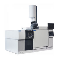
Triple Quadrupole
Brand:
Agilent Technologies
| Category:
Laboratory Equipment
| Size: 16.67 MB
Table of Contents
Table of Contents
3
1 Introduction
12
Abbreviations Used
12
The 7000/7010 Series TQ GC/MS
14
7000/7010 CI MS System
15
TQ GC/MS Hardware Description
16
Important Safety Warnings
17
Hydrogen Safety
19
Safety and Regulatory Certifications
22
Intended Use
26
Cleaning/Recycling the Product
26
Accidental Liquid Spill
26
Moving or Storing the MS
26
2 Installing 7890 GC Columns
28
Columns
28
To Install a Capillary Column in a Split/Splitless Inlet
30
To Condition a Capillary Column
33
To Install a Capillary Column in the GC/MS Interface Using the Self Tightening Column Nut
34
To Install a Capillary Column in the GC/MS Interface Using a Standard Column Nut
39
To Install the Interface Tip Seal
42
The GC/MS Interface for a 7890 Series GC
44
To Calibrate the Column
46
3 Intuvo 9000 GC Column Maintenance
50
Columns
50
Conditioning Intuvo Columns
51
Tips and Hints
51
Handling the Intuvo 9000GC Column and Bus Components
52
To Replace an Intuvo GC Column
53
To Replace an Intuvo 9000 GC Gasket
57
To Install a Column Guard or Jumper Chip
58
To Replace the 9000 GC/MS Tail
62
To Condition an Intuvo Capillary Column
66
To Install the Interface Tip Seal
68
The GC/MS Interface for a 9000 Series GC
69
4 Operating in EI Mode
72
Operating the MS from the Data System
72
Set the IP Address and View TQ Parameters with the WUI
73
To Change the Network Settings of the TQ
73
Front Panel Instrument Status LED
77
Before You Turn on the MS
78
Pumping down
79
Controlling Temperatures
79
Controlling Column Flow
80
Controlling CC Flow
80
Controlling Jetclean Hydrogen Flow
80
Venting the MS
81
High Vacuum Pressure in EI Mode
82
To Set Monitors for MS Temperature and Vacuum Status
83
To Set the MS Analyzer's Temperatures
85
To Set the GC/MS Interface Temperature from Masshunter
87
To Configure CC Gas
88
To Set the Mode for the Optional Jetclean System
89
To Set the Jetclean Parameters for the Clean Only Mode
90
To Set the CC Gas Flow Rates
91
To Autotune the MS for EI Mode
92
To Open Left Side Panel for Access to the Analyzer Chambers
94
To Pumpdown the MS
95
To Vent the MS
99
To Set the Interface Temperature from the 7890 GC
101
To Save a Method on the 7890 GC
102
5 Operating in CI Mode
104
Setting up Your MS to Operate in CI Mode
104
Operating the CI MS
105
High Vacuum Pressure in CI Mode
106
Other Reagent Gases
107
CI Autotune
109
The CI Flow Control Module
111
To Operate the Reagent Gas Flow Control Module
113
To Set a Reagent Gas Flow
115
To Perform a CI Autotune
116
To Pumpdown and Switch from EI to CI Mode
118
6 General Maintenance
122
Before Starting
122
Maintaining the Vacuum System
127
Maintaining the Analyzer
128
To Open the Front Analyzer Chamber
130
To Remove the EI HES
133
To Connect or Disconnect Wiring to the EI HES
135
To Remove the EI XTR Source
136
To Connect or Disconnect Wiring to the EI XTR Source
138
To Disassemble the EI HES
139
To Disassemble the EI XTR Source
142
To Clean the EI HES
145
To Clean the EI XTR Source
148
To Assemble the EI HES
151
To Assemble the EI XTR Source
156
To Install the EI HES
159
To Install the EI XTR Source
161
To Remove a Filament from the EI XTR Source
163
To Install a Filament on the EI XTR Source
165
To Remove the EI HES Filaments
166
To Install the EI HES Filaments
168
To Close the Front Analyzer Chamber
169
To Remove Left Rear Cover
170
To Open the Rear Analyzer Chamber
172
To Replace the EM Horn
175
To Close the Rear Analyzer Chamber
177
101 CI Maintenance
180
General Information
180
To Set up Your MS for CI Operation
180
To Switch from an EI XTR Source to the CI Source
181
To Remove the EI HES Radiator
182
To Connect or Disconnect EI HES Radiator Wiring
184
To Install the 7010 Series CI Source
185
To Install the 7000 Series CI Source
186
To Switch from the CI Source to the EI HES
187
To Install the EI HES Radiator
188
To Switch from the CI Source to the EI XTR Source
190
To Connect or Disconnect 7010 Series CI Source Wiring
191
To Connect or Disconnect 7000 Series CI Source Wiring
192
To Switch from the CI Source to an EI XTR Source
193
To Remove the 7000 Series CI Source
194
To Remove the 7010 Series CI Source
195
To Switch from the EI HES to the CI Source
196
To Install the CI/EI XTR Source Radiator
197
To Switch from the CI Source to the EI HES
199
To Install a CI Source Filament
200
To Remove the CI Source Radiator from the 7010 Series TQ
201
To Disassemble the CI Source
203
To Clean the CI Source
206
To Assemble the CI Source
209
To Remove the CI Source Filament
212
To Install a CI Source Filament
214
Advertisement
Related Products
Agilent Technologies 708-DS
Agilent Technologies 7000 Triple Quadrupole
Agilent Technologies 7000 Triple Quadrupole GC/MS
Agilent Technologies 709-DS
Agilent Technologies 7500 ICP-MS
Agilent Technologies 7673
Agilent Technologies 7890 Series
Agilent Technologies 7890B
Agilent Technologies 7820 VL MSD
Agilent Technologies 7890A GC
Agilent Technologies Categories
Measuring Instruments
Laboratory Equipment
Test Equipment
Water Pump
Power Supply
More Agilent Technologies Manuals
Login
Sign In
OR
Sign in with Facebook
Sign in with Google
Upload manual
Upload from disk
Upload from URL