Table of Contents
Advertisement
Quick Links
Advertisement
Table of Contents

Related Manuals for UNI-T UT3500 Series


Summary of Contents for UNI-T UT3500 Series
- Page 1 UT3500 Series Battery Internal Resistance Tester User Manual www.uni-trend.com...
-
Page 2: Preface
If the product is proved to be defective within the warranty period, UNI-T reserves the rights to either repair the defective product without charging of parts and labor, or exchange the defected product to a working equivalent product (determined by UNI-T). -
Page 3: Guarantee Limit
This warranty is written by UNI-T for this product and it is used to substitute any other express or implied warranties. UNI-T and its distributors do not offer any implied warranties for merchantability or applicability purposes. - Page 4 UT3500 series User Manual Do not use the instrument in flammable and explosive gas, steam or dusty environment. The use of any electronic equipment in such an environment is a risk to personal safety. Do not open the housing of the instrument: Non-professional maintenance personnel should not open the housing of the instrument to try to repair the instrument.
-
Page 5: Table Of Contents
UT3500 series User Manual Table of Contents Preface .............................. 2 Copyright Information ........................2 Warranty Service ..........................2 Guarantee Limit ..........................3 Safety Information ..........................3 1. Product Overview ......................... 8 1.1 Product Series ........................8 1.1.1 Features of Product Series ..................8 1.1.2 Main Functions of the Product ................. - Page 6 UT3500 series User Manual 4.2 Manual Save and View Data ....................25 4.3 Screen Capture Function ....................26 5. [Setup] Setting ..........................27 5.1 Parameters of Measurement .................... 27 5.1.1 [Average] Times ...................... 27 5.1.2 Trigger [Delay] ......................27 5.1.3 [Self-Calibration] Switch ..................28 5.1.4 Measurement [Current] Output Mode ..............
- Page 7 UT3500 series User Manual 8.1.9 [End Mark], [Hand Shake], [Error Code] Setting............. 43 8.1.10 SCPI [Upload] Mode ..................... 45 8.1.11 [Log] and [Stat] ..................... 45 8.1.12 [Filter] Selection ....................45 8.1.13 [Default Setting] ....................45 8.2 System Info ........................46 8.3 System Service........................
-
Page 8: Product Overview
Rear Panel 1.1 Product Series UT3500 series battery internal resistance tester contains two models: UT3562 and UT3563, the measurement voltage range of which is 100V and 400V respectively. The measurement accuracy is shown in the table below, and the complete technical specifications can be found in the last chapter. -
Page 9: Main Functions Of The Product
UT3500 series User Manual It can be used for professional sorting function, independent comparison function of resistance and voltage, and judgment of HI/IN/LO. The judgment result can be displayed on the screen, buzzer, and external I/O output. It can automatically judge whether the battery parameters meet the standards and count the pass rate, which is suitable for the detection and sorting of various batteries. - Page 10 UT3500 series User Manual There are two sorting results: PASS and FAIL, outputting in symbols respectively. Comparison Method: Absolute value tolerance ± TOL sorting: The absolute deviation of the measured value and the nominal value is compared with the limits of each range.
-
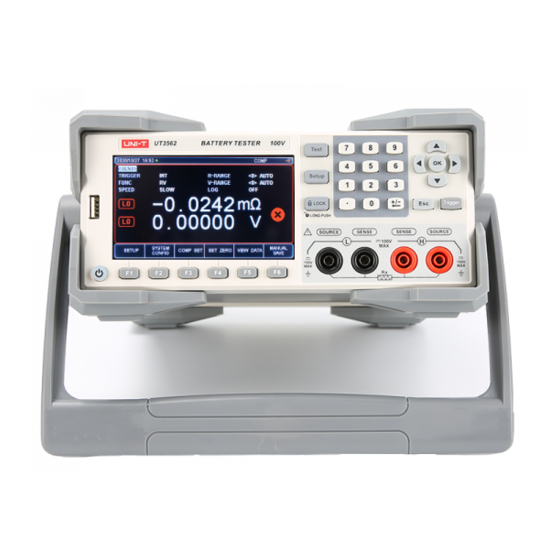
Page 11: Front Panel
UT3500 series User Manual 1.2 Front Panel 1.2.1 Description of the Front Panel Figure 1-2-1 Front Panel, Take UT3563 as an Example Serial Number Picture Description of Function Power switch (touch switch); When the power supply is ON, the button light is yellow. When OFF, it is red. - Page 12 UT3500 series User Manual ② When inserting the U disk, the screen image can be captured and saved. The esc key: It is used to cancel/return. The trigger key is used to trigger a measurement when the trigger source is external.
-
Page 13: Rear Panel
UT3500 series User Manual 1.3 Rear Panel Figure 1-3-1 Rear Panel 1. AC power socket (without fuse, it is inside the instrument). The power supply’s voltage and frequency are marked above the socket. 2. Ground Terminal 3. USB Communication Interface 4. -
Page 14: Requirements Of Power Supply
User Manual download from the official website. 2.2 Requirements of Power Supply UT3500 series can only be used under the following power supply conditions: Voltage: 100VAC~240VAC Frequency: 50Hz~60Hz Warning: In order to prevent the risk of electric shock, please connect the ground wire of the power supply. -
Page 15: Handle Of Instrument
UT3500 series User Manual 2.5 Handle of Instrument The handle of the instrument can be adjusted. Hold both sides of the handle at the same time with hands, gently pull it to both sides, and then rotate the handle. The handle can be... -
Page 16: Preparation Before Measurement
3.2 Connection of Test Terminals 3.2.1 Introduction of Test Lead UT3500 series battery internal resistance tester is equipped with UT-L80 crown probe test pen and UT-L82 Kelvin test lead specially used for battery internal resistance test according to the standards, which is convenient for users to measure more professionally. -
Page 17: Connection Of Test Lead
UT3500 series User Manual Red Crown Probe Test Pen Black Black Crown Probe Test Pen Figure 3-2-1 A UT-L80 Battery Internal Resistance Test Pen-Crown Probe (Standard Accessory) Red Nipper Clip Black Black Nipper Clip Figure 3-2-1 B UT-L82 Battery Internal Resistance Kelvin Test Lead- Nipper Clip... -
Page 18: Measurement Method Of Dut
UT3500 series User Manual Figure 3-2-2 Schematic Diagram of the Connection between the Test Lead and the Terminal Hole of the Instrument (Take the UT3563 Panel as an Example) ▲ The red test lead has only one side with the red symbol, when it is correctly connected, ▲... -
Page 19: Set Zero And Calibrate
UT3500 series User Manual If you are testing with an alligator clip, you can use the test lead to directly clamp the terminal of the DUT for four-terminal testing. If you are testing with a crown probe test pen, you can put the red and black test lead probes against the corresponding positive and negative terminals of the DUT for four- terminal testing, as shown in Figure 3-3-2. - Page 20 UT3500 series User Manual Figure 3-4-1 Alligator Clips Are Opened before Engaging 2. As shown in Figure 3-4-2, make the first row of teeth of one of the alligator clips properly engage with the first row of tooth recesses of the other alligator clip. The state after proper engagement should be the same as Figure 3-4-3.
- Page 21 UT3500 series User Manual Figure 3-4-4-a Crown Probe Test Pen Short Circuit Diagram a Second, apply force in the direction of the arrow shown in Figure 3-4-4-b to make the surface of the object at the third red point contact, that is, the periphery probe is in contact with the peripheral probe (Source and Source).
-
Page 22: Set Zero
UT3500 series User Manual the red test clip is located above the grip direction, and the short upper handle of the black test clip is located above the grip direction of the other hand. Do not cross the left, right, up and down handles. -
Page 23: Test] Measurement Page
UT3500 series User Manual 6. If setting zero fails, there will be a warning message "Correction fail" on the top of the screen. Please check whether the test terminals are properly short-circuited, and perform the setting zero step after the test terminals are correctly short-circuited according to step 4 above. -
Page 24: Trigger]
UT3500 series User Manual 4.1.1 [Trigger] The instrument has 2 trigger modes: internal trigger and external trigger (including manual/HANDLER/remote). Function Description of Function Also called continuous test, the trigger signal is continuously tested by the internal of the instrument according to inherent cycle. -
Page 25: R-Range]
UT3500 series User Manual 4.1.3 [R-Range] The resistance of the UT3500 series battery internal resistance tester has 7 ranges, divided into manual and automatic mode, as shown in the following table 4-1-2: Table 4-1-2 Range Selection Method and Variation Range... -
Page 26: V-Range]
UT3500 series User Manual 4.1.4 [V-Range] Voltage range setting: The voltage of the UT3500 series battery internal resistance tester has 3 ranges and two range selection modes: automatic and manual. Table 4-1-4 Range Selection Mode and Variation Range Range Method... -
Page 27: Manual Save And View Data
UT3500 series User Manual Setting Steps: 1. Press the [Test] key to enter the <TEST> page or press the [Setup] key to enter the <Setup> page; 2. Use the cursor key ▼ to move the cursor to the [SPEED] field;... -
Page 28: Screen Capture Function
UT3500 series User Manual this row of data. 4.3 Screen Capture Function The instrument provides a screen capture function. Insert a USB storage device into the USB interface on the front panel of the instrument, and press the [OK] key on the panel to save the current screen capture to the USB storage disk for subsequent reference. -
Page 29: Average] Times
UT3500 series User Manual 5.1.1 [Average] Times "Average" is one of the most commonly used digital filter, and the "number" is the depth of the filter. Its purpose is to perform multiply measurements and take the average result as the final display value, which can improve the stability and reliability of the measurement results. -
Page 30: Measurement [Current] Output Mode
UT3500 series User Manual control lead is used for self-calibration. To ensure accuracy, the instrument will perform a self-calibration every time it is turned on. 5.1.4 Measurement [Current] Output Mode When multiple identical instruments measure in parallel at the same time, the measurement signals will interfere with each other, causing sudden changes in the measured value. -
Page 31: Auto Save]
UT3500 series User Manual Setting Steps: 1. Enter the <CATALOG> page through the function key at the bottom of the <SETUP> or <COMP SET> page; 2. Use the cursor keys to select the [Auto Recall] field; 3. According to your own needs, use the function keys at the bottom of the screen to select File 0 or CURRENT FILE. -
Page 32: Log/Stat
UT3500 series User Manual 6. Log/Stat 6.1 Data Log 6.1.1 Enable Log Function The instrument has a data [LOG] function, which can log 10,000 sets of data. Through the data logging function, the measurement data can be stored in the instrument buffer in time. -
Page 33: Save Data
UT3500 series User Manual Figure 6-1-1-2 Start Logging Once the data logging is started, the test page will be locked and cannot be switched to other pages. In the external trigger state, before switching to other pages, data logging must also be closed. If switching from other pages to the <TEST> page, data logging will automatically start. - Page 34 UT3500 series User Manual Figure 6-1-3 Before Modifying Figure 6-1-4 After Modifying The specific cell modification steps are as follows: 1. You need to modify the format of the TIME field, select the time row and column, right-click to select "Set Cell Format", select "Custom" on the left side of the opened cell format window, and enter yyyy-m-d hh:mm:ss in the red box.
-
Page 35: Stat
UT3500 series User Manual 6.2 Stat 6.2.1 Process Capability Index Process capability refers to the ability of process processing to meet processing quality. It measures the internal consistency of process processing and the smallest fluctuation in the most stable state. When the process is in a steady state, 99.73% of the product quality characteristic values are scattered in the interval [μ-3σ, μ+3σ]... -
Page 36: Turn On The Stat Function
UT3500 series User Manual 6.2.2 Turn on the Stat Function Setting Steps: 1. Press the [Setup] button to enter the <Setup> page, select the function key corresponding to the [SYSTEM CONFIG] at the bottom of the screen and press it to enter the <SYSTEM CONFIG>... -
Page 37: Save Data To U Disk
UT3500 series User Manual 6. After the data statistics are automatically started, you can use the function key to stop the current statistics at any time; you can also save the data to the U disk at any time; you can also stop and clear the cached data, as shown in Figure 6-2-3. -
Page 38: Comparator Setting
UT3500 series User Manual 7.1 Comparator Setting Figure 7-1 <COMP SET> Page 7.1.1 [Beep] Setting The beep function is effective only after the comparator function is turned on. There are three types of beep settings: PASS, FAIL, OFF. PASS: the buzzer will sound when the sorting result is qualified. FAIL: the buzzer will sound when the sorting result is unqualified. -
Page 39: Nominal Value] Input
UT3500 series User Manual 2. Use the cursor keys to move the cursor to the [R-COMP] or [V-COMP] field to select 3. Move the cursor to the [MODE] field, and use the function keys at the bottom of the screen to select the desired comparison mode among the three according to your needs. -
Page 40: Example Of Qualified Discrimination
UT3500 series User Manual Figure 7-2-1 Page to Be Measured after the Comparator Is Turned on After the comparator is turned on, the "COMP" logo will appear at the top of the screen, which means that the comparator function has been turned on at this time. Because... -
Page 41: Example Of Unqualified Discrimination
UT3500 series User Manual of this group of test data as qualified, and a qualified mark will appear on the screen. If the buzzer is set to "beep when qualified" at this time, the instrument will emit a qualified buzzer for the qualified situation. -
Page 42: Language] Setting
UT3500 series User Manual the bottom of the screen. Press the corresponding function key can enter the <SYSTEM CONFIG> page. All settings on the system configuration page will be automatically saved in the system and loaded automatically when the system is turned on next time. -
Page 43: Account Setting
UT3500 series User Manual the bottom of the screen to enter the < SYSTEM CONFIG> page; 2. Use the cursor keys to move the cursor to the [Date] or [TIME] field; 3. According to your own needs, press the function keys at the bottom of the screen to select the year, month, day, hour, minute and second that you want to set. -
Page 44: Baud] Setting
UT3500 series User Manual 8.1.6 [Baud] Setting The instrument has built-in RS-232 and USB-232 interfaces. After the instrument senses the signal conversion of the RS-232 or USB interface, it immediately communicates with the host at the set baud rate and the keyboard is locked. In order to communicate correctly, it is necessary to confirm whether the baud rate and stop bit are set correctly, otherwise the upper computer cannot communicate correctly. -
Page 45: End Mark], [Hand Shake], [Error Code] Setting
UT3500 series User Manual the bottom of the screen to enter the <SYSTEM CONFIG> page; 2. Use the cursor keys to move the cursor to the [ADDRESS] field; 3. According to your own needs, press the function keys at the bottom of the screen to select different addresses from 01 to 15. -
Page 46: Scpi [Upload] Mode
UT3500 series User Manual Setting Steps: 1. Press the [Test] or [Setup] key, and select [SYSTEM CONFIG] with the function key at the bottom of the screen to enter the <SYSTEM CONFIG> page; 2. Use the cursor keys to move the cursor to the [HAND SHAKE] field;... -
Page 47: Filter] Selection
UT3500 series User Manual 8.1.12 [Filter] Selection The measurement stability of the instrument depends on the filter. Please select according to the filter of the current region. If you are not sure, please select AUTO. The instrument will automatically set the filter of the current region. The filter in China is 50 Hz. -
Page 48: System Info
UT3500 series User Manual 3. The <CATALOG> page is preset to file 0: the shutdown save is set to be prohibited: 8.2 System Info Press the [Test] or [Setup] key, and select [SYSTEM CONFIG] with the function key at the bottom of the screen to enter the <SYSTEM CONFIG>... -
Page 49: Terminals And Signals
UT3500 series User Manual 9.1 Terminals and Signals Table 9-1 Definition of Output Terminal Pin Name Description Table 9-1 Terminals Output Terminal (All signals are active low) Table 9-2 Definition of Input Terminal Pin Name Description TRIG The rising edge is valid. -
Page 50: Electrical Parameters
UT3500 series User Manual When the power is unknown or uncertain, the internal power supply cannot be used, otherwise the instrument will not work normally. In known low-power occasions, you can use the internal power supply to work, but the anti-interference ability of the instrument may deteriorate. -
Page 51: Connection Method Of The Input Circuit
UT3500 series User Manual 9.2.5 Connection Method of the Input Circuit Figure 9-2-5-1 Connection with the Switch Figure 9-2-5-2 Use Relay to Control Figure 9-2-5-3 Use PLC Negative Common Terminal to Control Figure 9-2-5-4 Use PLC Negative Common Terminal to Control... -
Page 52: Connection Method Of The Output Circuit
UT3500 series User Manual 9.2.6 Connection Method of the Output Circuit Figure 9-2-6-1 Control Relay Figure 9-2-6-2 Control Luminous Diode and Optical Coupler Figure 9-2-6-3 Negative Logic Output... -
Page 53: Periodic Table
UT3500 series User Manual Figure 9-2-6-4 Composition Logic or Circuit of Two-Port Output Figure 9-2-6-5 Output to PLC Negative Common Terminal Figure 9-2-6-7 Output to PLC Positive Common Terminal 9.3 Periodic Table Figure 9-3-1 Periodic Table Description Minimum Trigger Pulse Width Trigger Delay <10μs... -
Page 54: Remote Communication
UT3500 series User Manual 10. Remote Communication This chapter mainly covers the following: RS-232 Interface and Connection RS-485 Interface USB Interface Communication Protocol The instrument uses RS-232 interface (standard configuration) to communicate with the computer to complete all the functions. Through standard SCPl commands, users can also easily compile various collection systems suitable for themselves. -
Page 55: Rs232C Interface
UT3500 series User Manual Table 10-1-2 Minimum Subset of RS232 Standard Signal Symbol Pin No. of 9-Core Connector Transmit Data Receive Data Ground 10.1.1 RS232C Interface Figure 10-1-1 RS-232 Interface on the Rear Panel [Male] Suggestion: To avoid electrical shock, please turn off the power of the instrument when plugging or unplugging the connector. -
Page 56: Rs485 Interface
UT3500 series User Manual 10.2 RS485 Interface The instrument is equipped with RS485 interface as standard. The RS485 interface and the RS232 interface of the instrument share the same DB9 terminal: RS485 is a communication interface that supports multi-machine communication, which can be connected with multiple slaves through one host. -
Page 57: Communication Protocol
UT3500 series User Manual 2. In the device manager on the computer, it will be prompted as "other devices". At this time, you need to install the driver. 3. You need to download the CH340 driver (you can download it from the browser by yourself). -
Page 58: Technical Index
UT3500 series User Manual The SCPI protocol defines a set of standard syntaxes and commands for controlling programmable test and measurement instruments. SCPI commands are transmitted using the ASCII character string and passed into the instrument through the physical transport layer. - Page 59 UT3500 series User Manual 0.5%rdg. ±20dgt ± High- ±1%rdg. ±8dgt 0.5%rdg. Speed ±40dgt (± 0.05%rdg. (±0.05%rdg. ±0.5dgt.)/ ℃ Temperature Index ± 1dgt)/ ℃ Voltage Measurement <2>100V [UT3562] Voltage Range <0>6V <1>60V <2>400V [UT3563] ±101.000V [UT3562] ±6.06000V ±60.6000V Maximum Display Value ±404.000V...
-
Page 60: Environmental Requirements
UT3500 series User Manual 11.2 Environmental Requirements Index Environment: Temperature 18℃~28℃ Humidity ≤65%RH Operating Environment: Temperature 10℃~40℃ Humidity 10~80%RH Storage Environment: Temperature 0℃~50℃ Humidity 10~90%RH Power Supply: 100VAC~240VAC Fuse: 250V 1A Slow Melting Power: Maximum 20VA Machine Weight: About 2.6 kg (Net Weight, without Accessories)