Table of Contents
Advertisement
Advertisement
Table of Contents

Related Manuals for UNI-T UTD1000L Series


Summary of Contents for UNI-T UTD1000L Series
- Page 1 User Manual UTD1000L Series DIGITAL STORAGE OSCILLOSCOPE...
- Page 2 2011 . 0 9 U NI-T Technologies, Inc. ...
- Page 4 Preface Dear users, Thank you for purchasing UNI-T product. To operate the Oscilloscope correctly, please read this Manual carefully and especially its “Safety Information” before use. Afer reading it, you are suggested to keep the manual properly. Please keep it with the Oscilloscope together or place it in an accessible location for future use.
- Page 5 The warranty is signed by UNI-T with respect to the product in lieu of any other expressed or implied warranties. UNI-T and its distributor refuse any implied warranty for marketability or suitability with special purpose.
-
Page 6: Table Of Contents
Table of Contents P R EFACE C I O PYRIGHT N FORMATION T C A BLE O F O NTENTS C 1 S I H APTER A FETY N FORMATION 1.1 S T S A FETY E RMS A ND... - Page 7 4.23 S AC C E LECTING O UPLING 4.24 I W D N VERTING T HE A VEFORM I SPLAY 4.25 A S DC O U TOSET F OR I GNALS W ITH F FSET C 5 U...
- Page 8 C 8 S S H APTER E RVICE A ND U PPORT 8.1 U P P DATING R OGRAM 8.1.1 Preparation before Update 8.1.2 Update Conditions 8.1.3 Program Update C 9 A H APTER P PENDIXES A A: T S...
-
Page 9: Chapter 1 Safety Information
Warning: If the Oscilloscope terminals are input with voltages higher than 42 V (30 Vrms), to avoid personal electric shock: ●Use only the insulated voltage probe, test leads and power adaptor supplied or specified by UNI-T for this Oscilloscope Series. - Page 10 ●Do not input voltages higher than 3 00V i n to scope terminals under CAT I I m easuring environment; working voltage applied into multimeter terminals must not exceed 600V u nder CATIII m easuring environment.
-
Page 11: Utd1000L S E Rieso
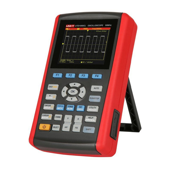
Dual Channel UTD1000L Series Oscilloscopes offer users a simple and clear front panel that helps to perform primary operations , a design you often get used to and can save you a great amount of time to learn about the Oscilloscope. -
Page 12: Multimeter
● I solated USB for much safer communication; ● C olor, White& black display f or your option, perfect for use outdoors with strong sunshine. ● I ntelligent local or network software update ● U nique waveform record, storage and recall functions ●... -
Page 13: C H Apter 3 C O Nnectionst O T Heo
If the Oscilloscope is found damaged externally or it does not work normally or pass any performance test, contact our UNI-T dealership or local UNI-T office If the product is damaged due to the transit, keep the package and inform the shipping agency and UNI-T dealership, UNI-T will arrange the maintenance or replacement for you. -
Page 14: Compensation Output Connection
Connect to the output (1 kHz/3V) terminal as shown below for the Oscilloscope probe compensation. Figure 3-2 Compensation Output Connection 3.3 Front Panel and Keypad Learn about the Oscilloscope front panel and buttons shown in Figure 3-3: Figure 3-3 UTD1000L Series Front Panel UTD1000L User Manual 1 1... - Page 15 : To power on/off the Oscilloscope F1~F4: To set up the submenus : To toggle between Scope (DSO) and multimeter (DMM) modes. : Press this button to access ACQUIRE (sample mode) menu if under DSO mode; press SHIFT first and then this button to access intensity, with help of right and left arrow buttons, you can change screen brightness.
- Page 16 : Combine with other buttons to select function options Timebase: To change scan rate, ranging from 50s/div~10ns/div for 25MHz-bandwidth models and 50s/div~5ns/div for 50MHz-bandwidth models and stepping in 1-2-5. Press “s” to access relatively slower scan rate or “ns” to speed up. Vertical Scale: To change vertical scaling, ranging from 5mV/div~20V/div and stepping in 1-2-5.
-
Page 17: C H Apter 4 U S Ing B A Sic O S Cilloscope
4.2 Powering on the Oscilloscope UTD1000L Series can be powered by: the battery and power adaptor. The power supply voltage from the adaptor is DC9V/1.5A. To operate the Oscilloscope normally, please use the power adaptor specified for the Oscilloscope. -
Page 18: Resetting The Oscilloscope
6. The power supply indicator: ● The Oscilloscope is powered by the battery; The Oscilloscope is powered by DC power adaptor. 7. The marker for ground reference point for displayed waveforms; 8.1×: indicates probe attenuation factor for the channel is 1×; 9. -
Page 19: Using Functional Menus
4.5 Using Functional Menus The procedures below show you how to select functions with use of oscilloscope menus; 1. Press any functional button on the keypad, then corresponding options will show on the bottom display, you can select one of these options with use of F1 ~ F4. After that, press OK button to hide functional menus;... -
Page 20: Compensating The Probe
Figure 4-4 Adjusting Probe Factor 3. Conenct the probe to the output terminal for probe compensation on the Oscilloscope, press AUTObutton, after several seconds, squarewave displays (1kHz, 3Vpp, Peak-to-Peak Value), See Figure 4-5. Figure 4-5 Squarewave Signal from the Oscilloscope Itself 4.8 Compensating the Probe You need to compensate the probe whenever connecting it to channels for the first time so as to match the probe to the input channel. -
Page 21: S E Tting V E Rtical & H O Rizontal
4.9 Setting Vertical&Horizontal Systems and Trigger Level Manually 4.9.1 Vertical System Press V~mV buttons to adjust the vertical scale(VOLT/DIV) and display waveform with proper size on the screen; When channel cursor turns solid, press Up and Down button to adjust ground reference point that can allow the waveform to display at proper location;... -
Page 22: A U Tosetf Or W A Veformd
4.10 Autoset for Waveform Display UTD1000L Series is designed with autoset function that can automatically adjust the vertical scale, scan timebase and trigger mode based on the input signal until the optimal waveform can be obtained. To apply the autoset function, the tested signal should have a frequency at ≥20Hz and duty cycle>1﹪;... -
Page 23: Run/Stop Data Acquisition
Figure 4-9 Full Autoset Note: 1. Under autoset mode, trigger mode is set to “Auto” and cannot change. 2. Once you are in autoset mode, following settings are forced to execute: (1) The Oscilloscope will switch into main timebase status if the current display isn’t under this status; (2) The coupling mode will be set to AC mode and allows no change. -
Page 24: Saving Bitmap
2. Press ACQUIRE button and select backlight menu; 3. Press F1 to switch on backlight intensity bar; 4. Press Left and Right arrow buttons to adjust the intensity to proper value; 5. Press F1 to switch off the backlight intensity bar. Note: Press down AUTO button, the backlight intensity bar will switch off automatically. -
Page 25: Setting Single Trigger
Figure 4-12 Help System 4.16 Setting Single Trigger To set trigger mode to Single directly, do the following: 1. Press SINGLE button, the Oscilloscope will be set under single trigger mode immediately. Figure 4-13 Single Trigger 4.17 Viewing Oscilloscope Status To view the current status of the Oscilloscope, do the following: 1. -
Page 26: C H Ecking O S Cilloscope S Y Stem
Figure 4-14 UTD1000L Status Information 4.18 Checking Oscilloscope System Information To check the system configuration of the Oscilloscope, do the following: 1. Press SHIFT and shift icon shows on upper right corner of screen; 2. Press CONFIGUREbutton to switch on display configuration menu; 3. -
Page 27: Measuring All Parameters
4.19.1 Measuring All Parameters To measure automatically all parameters, do the following: 1. Press MEASURE button to display measurement menu; 2. PressF2, then the screen will show measurement results for all parameters. Note: 1) Switching between different signal sources in UTD1000DL will change the paramteters accordingly for channels;... -
Page 28: U S Ing Avgm Odef Ors
Figure 4-17 UTD1000L Customized Measurement 4.20 Using AVG mode for Smoothing Waveforms To smooth the waveforms, do the following: 1. Press ACQUIR button to display sample mode; 2. Press F1 button to set sample mode to AVG; 3. Press Left and Right arrow buttons to set AVG number to 1 6 . Then measurement results will show after the Oscilloscope has averaged the data for 16 times. -
Page 29: O B Serving W A Veformsw Ith
Figure 4-19 Sampling with Peak Detect Mode 4.22 Observing Waveforms with use of Persistence Select the Persistence function if you want to observe continuously the dynamic signals. 1. Press DISPLAY button to show D isplay Mode menu; 2. Keep pressing F4 button to select between 1sec, 3sec, 5sec, Infinite or Auto options. If display mode is set to ... -
Page 30: I N Vertingt He W A Veformd
Figure 4-22 UTD1000L Inverted Waveform 4.25 Autoset for Signals with DC Offset UTD1000L Series is designed with powerful autoset function that makes it possible to perform fast and accurate measurement in DC–coupled mode for signals with any DC component. UTD1000L User Manual... - Page 31 Position parameter on upper right display of screen: This parameter stands for position readout for the channel reference marker that moves from horizontal central line, if it is positive value, it indicates the channel marker is above the horizontal central line and the negative one is for the marker below the horizontal central line.
-
Page 32: Chapter 5 Using The Multimeter
With the comparison shown above, it is very clear that UTD1000L series is designed with a powerful ability to measure signals at much faster speed and in a more visual way. Chapter 5 Using the Multimeter 5.1 About the Chapter This chapter introduces the multimeter functions built in the Oscilloscope;... -
Page 33: M A King M U Ltimeter
AC Current Measurement Resistance Measurement Diode Test Continuity Test Capacitance Measurement 4. Relative Measurement 5. working statusIndicator; HOLD : Freeze the display 6. Main Display for Measuring Values 7. Manual Ranging Indicator 5.4 Making Multimeter Measurements Press DSO/ DMM button to access DMM mode, the display then enters into the multimeter interface. Multimeter functions are ready to use at the moment. -
Page 34: Testing For Continuity
Fgiure 5-2 Testing Diode 5.4.3 Testing for Continuity To check the continutity, do the following: 1. Press R t o set the measurement type to R esistance . 2. Press F 1 b utton to select C ontinutity . 3. -
Page 35: Measuring Dc Voltage
Figure 5-4 Measuring Capacitance 5.4.5 Measuring DC Voltage To measure DC voltage, do the following: 1. Press down V b utton to set measurement type to D C Voltage. 2. Plug test lead connectors into multimeter input terminals (Black to C OM a nd Red to V /Ω ) . 3. -
Page 36: Measuring Dc Current With Utd1000Cl
Figure 5-6 Measuring AC Voltage 5.4.7 Measuring DC Current with UTD1000CL To measure DC current equal to or lower than 4mA, do the following: 1. Press I button to set measurement type to D C Current , t he m easurement unit is μ A, y ou can use F 3 to toggle between... -
Page 37: Measuring Ac Current With Utd1000Cl
Figure 5-8 Measuring DC Current lower than 400mA To measure DC current equal to or greater than 400mA, do the following: 1. Press I b utton to set measurement type to D C Current 2. Press F 3 button to select A range, and m easurement unit will be ... - Page 38 Figure 5-10 Measuring AC Current lower than 4Ma To measure AC current lower than 400mA, do the following: 1. Press I button to set measurement type to A C Current , 2. Press F 3 button to select m A range, andmeasurement unit will be m A . 3.
-
Page 39: Measuring Dc Current With Utd1000Dl
Figure 5-12 Measuring AC Current Greater Than 400mA 5.4.9 Measuring DC Current with UTD1000DL To measure DC current equal to or lower than 1mA, do the following: 1. Press I button to set measurement type to D C Current , t he m easurement unit is μ A, y ou can use F 3 to toggle between... - Page 40 Figure 5-14 Measuring DC Current Lower than 40mA To measure DC current within 40mA-400mA, do the following: 1. Press I button to set measurement type to D C Current. 2. Press F 3 to select m A range, and the measurement unit will display m A a ccordingly. 3.
-
Page 41: Measuring Ac Current With Utd1000Dl
3. P lug 4A current module ( U T-M04 ) into input terminals COM and V/Ω, then insert test leads properly into the module. 4. Connect test leads to tested points, then take DC current reading. Warning : If test leads are directly connected to V / Ω and C OM t erminals without use of 4A current module (... - Page 42 Figure 5-17 Measuring AC Current Equal to or Lower than 1mA To measure AC Current within 1mA-40mA, do the following: 1. Press I b utton to set measurement type to A C Current , 2. Press F 3 t o select m A range, the measurement unit will change into m A a ccordingly. 2.
- Page 43 5. Connect test leads to tested points, then take the AC current reading. Figure 5-19 Measuring AC Current within40mA-400mA To measure AC Current greater than 400mA, do the following: 1. Press I b utton to set measurement type to A C Current , 2.
-
Page 44: Data Hold
Figure 5-20 Measuring AC Current Greater than 400mA 5.5 Data Hold You can freeze the displayed readings any time as you want. 1. Press R UN /STOP to freeze measuring values, and H OLD i con blinks on the display 2. -
Page 45: S E Lecting M A Nual / A U Tor
Figure 5-22 Measuring Capacitanc in Relative Mode 5.7 Selecting Manual/Auto Ranging The multimeter defaults at auto mode. To access manual ranging, operate as follows: 1. Press V o r R b utton, a nd measure mode option is A UTO . 2. -
Page 46: C H Apter 6 U S Ingt He O S Cilloscope
Chapter 6 Using the Oscilloscope in Details 6.1 About the Chapter This chapter offers a step-by-step introduction on UTD1000L Series functions. Detail information about functional buttons on the front panel and operation examples are included here.It is recommended that you should read through this chapeter in order to get more and systematic knowledge of the Oscilloscope. - Page 47 Figure 6-2 Moving Waveform Vertically 2. Setting Waveform Display Press CHANNEL button to toggle between different channels. In the channel menu, pressF1 submenu button to turn on/off the waveform of the current channel. In order to on/off another channel waveform, you need to press CHANNEL button again before pressing F1 button Figure 6-3B Turn on Waveform Display for Dual Channels 3.
-
Page 48: Setting Horizontal System
100:1 100× 1000:1 1000× 6.3 Setting Horizontal System 6.3.1 Changing Timebase Press s/ns button slow down or speed up the scan rate from 10ns or 5ns/div~50s/div. Notes: For 25MHz-bandwidth models: 10ns/div~50s/div; 50MHz-bandwidth Models: 5ns/div~50s/div. 6.3.2 Moving Waveforms Horizontally Press Left and Right buttons to adjust pretrigger depth. The trigger location is usually set at horizontal center on the screen. -
Page 49: Adjusting Trigger Hold-Off
Figure 6-5 Screen Display under Window Zoom Under window zoom function, there are two separate display zones as indicated in the figure above. The upper part is for the original waveform. Press OK button and then use Left and Right buttons to select the waveform to be expanded on the left or right, or enlarge or narrow down the selected zone with s/ns button. -
Page 50: Setting Trigger System
Figure 6-6 Trigger Hold-Off Note: 1. The trigger hold-off time can be adjusted only when horizontal menu displays. 2. Generally hold-off time is a little smaller than “Big Period’, for instance for RS232 communication signal waveform, hold-off time should be a little larger than start edge time of each frame in order to easily observe the waveform. -
Page 51: Common Setting
Figure 6-7 Trigger Menu Trigger Controls Four trigger types are available: edge, video, pulse width and slope, every of which is coupled with different functional menu. There is still one type- common setting-- used to set up trigger source, trigger coupling and trigger modes. -
Page 52: Edge Trigger
Type Common to set up common trigger items Set CH1 as trigger source Source Set CH2 as trigger source DC component is blocked Couplin DC &AC components pass Reject high frequency component at > 8 0kHz Reject The Oscilloscope automatically acquires data when no Auto trigger signal has been detected. -
Page 53: Video Trigger
Figure 6-10 Trigger-Pulse Wdith Type Table 6-5 Menu Settings Description Type Pulse Set trigger Type to Pulse Width Width Polarity Positive Set positive pulse width as trigger signal. Negative Set negative pulse width as trigger signal. Qualifier Trigger when input pulse width equals to set value; <... -
Page 54: Slope Trigger
Figure 6-11 Trigger-Video Type Table 6-6 Menu Settings Description Type Video Set trigger Type to Video. Forma Trigger on PAL format video signal. NTSC Trigger on NTSC format video signal. All Lines Trigger synchronically on all lines. Odd Field Trigger on odd fields. Even Trigger on even fields. - Page 55 Figure 6-13 Trigger – Slope Type (Page 2) Table 6-7 Menu Settings Description Type Slope Set trigger Type to Slope Rise Trigger on rising edge that traverse between thresholds. Slope Type Fall Trigger on falling edge between thresholds > Trigger When the slope is greater than the set value of slew <...
-
Page 56: Setting The Display
3. Trigger Coupling: T o decide to pass which kind of components through the trigger circuits. The types include: DC, AC and Hf Reject. ■ D C: p asses through all components of the signal ■ AC: blocks DC component and attenuate signals at < 1 0Hz ■... -
Page 57: Setting Auto Measurements
Figure 6-14 Waveform Display Setup Table 6-9 Menu Settings Menu Type To display relationship between voltage(vertical) and time(Horizontal). X-Y display mode using CH1 signal to form X axis and CH2 signal for Y axis(applicable only for dual channel model) Format Vector Connect sample dots and display. - Page 58 Figure 6-15A UTD1000CL Auto Measurement Menu Figure 6-15B UTD1000DL Auto Measurement Menu Table 6-10 Menu Setting Description Sourc Select CH1 as the signal source. Select CH2 as the signal source. To measure all parameters. Turn on auto measurement function. Select To select the parameters to be measured by using SELECT button.The selected parameter will be displayed on the screen.
- Page 59 Figure 6-16A UTD1000CL measures all parameters Figure 6-16B UTD1000DL measures all parameters Case 2: To measure Vpp and Amplitude parameters, do the following: 1. Press MEASURE to open parameter measurement menu; 2. Press F2 of UTD1000CL (F2 ofUTD1000DL) button to open parameter selection box; 3.
- Page 60 Figure 6-17 Select Vpp Parameter Figure 6-18 Select Amplitude Parameter UTD1000L User Manual 5 7...
- Page 61 Figure 6-19 Display Selected Parameters Note : Parameter selection is to measure parameter immediately. There are 19 types of parameter measurements for UTD1000CL and 22 types available in UTD1000DL. Under general circumstances, not all parameters, but just some of them are required to be measured. Therefore the users can customize their measurements as expected.
-
Page 62: Recording And Storage
Average Value: The arithmetic mean over one cycle in the waveform RMS Value (Vrms): Effective value, the root mean square voltage over one cycle in AC signal waveform that corresponds toDC voltage with equal generated energy calculated in this cycle. Figure 6-21 Time Measurement The time parameters the Oscilloscope can automatically measure contain: RiseTime: The time required to rise from 10% to 90% of waveform amplitude. - Page 63 Figure 6-22 Waveform Record Menu Set up as the following table: Table 6-11 Record Menu Menu Setting Description Wave Record To turn on/off waveform record Record function. Play ---- To play recorded waveform Stop ---- To stop recording or playing waveforms Record ---- To begin the recording.
- Page 64 Location ---- There are 1-5 location options available, use arrow buttons to select when the menu displays Save ---- To save recorded waveform to internal memory. Recall ---- To recall the waveform record that is saved in internal memory Note: Y ou can also save the recorded waveform to PC using the control sofeware and play it on PC. Case 1: ...
-
Page 65: Storage
6.8.2 Storage To store the waveforms, do the following: 1. Press SHIFT button, and shift icon shows on upper right part of screen; 2. Press STORAGE button to access storage menu; Figure 6-25 Setting Waveform Storage Menu Figure 6-26A UTD1000CL Waveform Storage Menu ... -
Page 66: Recalling
Figure 6-26B UTD1000DL Waveform Storage Menu Set up the storage menu as follows: Table 6-13 Menu Settings Description Type Setup To save current setups of menus; Waveform To save channel waveforms Location 1-20 Use arrow buttons to select storage location. Source To select the channel of the saved waveform. -
Page 67: Making Cursor Measurements
Figure 6-27 Recall Reference Waveforms Set up as shown in the following table: Table 6-14 Settings Description REF A UTD1000L can recall REFA or REFB individually or both of them Wave REF B at the same time. Location 1-20 Use Right and Left buttons to select the location to be recalled. Recall To begin the recalling Clear... - Page 68 There are two options available for measuring Type in cursor menu: Voltage and Time. When measuring voltage, use SELECT and arrow buttons to adjust the locations of two cursors in order to measure ΔV parameter, do the same with Δt measurement. Voltage/Time Measurement Tips...
-
Page 69: Interface Setup
Figure 6-29 Cursor Menu for Voltage Measurement Table 6-16 Menu Settings Description Type Voltage Use the cursor to measure the voltage Mode Independent Move each cursor independently Move two cursors simultaneously and keep ΔV Tracking unchanged Func Switch Channel Use arrow buttons to set the target to channel Trigger waveform;... -
Page 70: Utility Setup
6.11 Utility Setup To set up the display interface for the Oscilloscope, do the following: 1. Press SHIFT, shift icon shows on upper right corner of the display; 2. Press UTILITY to access Utility menu. Menu Setup shown as in the following table: Table 6-18 Model UTD1000CL Functional Menu... - Page 71 Figure 6-30 UTD1000CL FFT Operation Refet to the menu setup in the following table: Table 6-19 Functional Menu Settings Description Turn on/off FFT function. Source CH1 is the default channel for FFT operation. Window Hanning Set to Hanning window. Hamming Set to Hamming window.
- Page 72 Figure 6-31 UTD1000DL MATH Operation Figure 6-32 UTD1000DL FFT Operation Set up Math and FFT menus as follows: Table 6-20 Type Settings Description ----- Turn off MATH function Source 1 Set CH1 as Source 1 of Math operation Set CH2 as Source 1 of Math operation +...
- Page 73 Set the source to CH2 Hanning Set to Hanning window Window Hamming Set to Hamming window Blackman Set to Blackman window Rectangle Set to Rectangle window Vertical Linear To set vertical unit to linear or dBV Unit FFT Spectrum Analysis FFT (Fast Fourier Transform algorithm) mode can convert time domain (YT) into Frequency domain for signal waveform graph, which helps to easily observe signals of following kinds: ●...
-
Page 74: Autoset
6.13 Autoset Autoset is used to simplify the operations. Press AUTObutton and then the Oscilloscope will automatically adjust vertical factor and timebase range based on the waveform amplitude and frequency until the waveform displays steadily on the screen. System settings for Autoset function are shown in the following table: Table 6-22 Functions... -
Page 75: Chapter 7 Troubleshooting
Chapter 8 Service and Support 8.1 Updating Program Contact UNI-T or log into our website to obtain the latest program package, unzip the package and apply the Oscilloscope program update system to update the Oscilloscope so as to ensure your oscilloscope has the latest version of firmware issued already by UNI-T ... - Page 76 Oscillosocpe model, hardware version, software version, etc. 2. Make sure the program package you get from UNI-T company or website has the same model number and hardware version with the Oscilloscope to be updated. The version should be higher than the current version.
- Page 77 2. If the Oscilloscope was disconnected to PC or powered off or PC has been shut down during update, the update would stop and leave the previous program unchanged. U TD1000L User Manual...
- Page 78 Chapter 9 Appendixes Appendix A: Technical Specifications Unless otherwisef specified, the technical specifications are all applicable for 10× probe and UTD1025L Oscilloscope. First of all, the Oscilloscope must satisfy two following conditions in order to mee those specifications: ■ The Oscilloscope must run continuously for more than 30 minutes in regulated working temperature. ■Users have to execute “self-calibration”procedure in UTILITY menu if operating temperature is 5℃...
- Page 79 200mV/div~1V/div: ±24V; 2V/div~20V/div: ±240V; UTD1025CL UTD1025DL 25MHz Analog Bandwidth UTD1050CL UTD1050DL 50MHz LF Response ≤10Hz(at BNC) (AC-Coupled, -3dB) UTD1025CL UTD1025DL : ≤14ns Rise Time UTD1050CL UTD1050DL : ≤7ns For vertial Sensitivity 5mV/div: ±4%(Normal or AVG) DC Gain Accuracy vertial Sensitivity from 10mV/div~20V/div: ±3% ( Normal or AVG) Where vertical offset equals zero and N≥16: ±(4%×Readings+0.1div+1mV) and select 5mV/div;...
- Page 80 Slope Trigger <, >,= Trigger Conditions Slew Rate 40pV/μs~1.6kV/μs Measurements Cursor Voltage Difference(ΔV), Cursor Time Difference(ΔT), Manual Mode ΔT reciprocal(Hz)(1/ΔT) Cursor Auto Mode Cursor allowed to display in auto mode Peak-to-Peak, Amplitude, Max, Min,Top Point, Bottom Point, Middle, AVG, RMS, Overshoot, Preshoot, Frequency, period, Auto Measurements Rise Time, Fall Time, Positive&Negative Pulse Width, Positive&...
- Page 81 10mv 40.00V 400.0V 100mv UTD1000DL DC Current : Max. Input DC Current: DC4A Range Resolution Accuracy 999.9μA 0.1μA ±(1.2%+5digits) Measure with UT-M10 (mA current module) 40.00mA 10μA Measure with UT-M10 (mA current module) ±(1%+5digits) 400.0mA 0.1mA Measure with UT-M10 (mA current module) 10mA 4.00A ...
- Page 82 400.0mA 0.1mA ±(1.5%+5digits) Measure with UT-M10 (mA current module) 10mA 4.00A Measure with UT-M04 ±(2.5%+5digits) (4A current divider module) UTD1000CL AC Current : Max. Input DC Current: DC6A Range Resolution Accuracy 350.0μA 0.1μA ±(2%+5digits) 40.00mA 10μA ±(1.5%+5digits) 400.0mA 0.1mA 10mA 6.00A Measure with UT-M07 ±(2.5%+5digits)
- Page 83 Display Color Color/Black&White Waveform Display Zone Horizontal: 12div, 25dot/div; Vertical: 8div, 25dot/div; Backlight Brightness Adjustable Backlight Intensity 300nit Language Multilingual Interface USB cable, 1 pc UTD1000DL: UT-M04(4A current divider module), 1pc, Standard UT-M10(mA current module), 1pc; UTD1000CL: UT-M07(10A current divider module), 1pc. Optional ---- Power Adaptor:...
- Page 84 1. Clean dust on the Oscilloscope and probe surface with soft cloth. Avoid any scratch to LCD transparent protective layer. 2. Clean with soft cloth damped with water or mild agent, no water drop is allowed to occur. Do not use any corrosives or abrasives.
- Page 85 This user manual may be revised without prior notice U TD1000L User Manual...