
Related Manuals for Agilent Technologies MS40+


Summary of Contents for Agilent Technologies MS40+
- Page 1 MS40+ Single Stage Rotary Vane Pumps Models: 9499225, 9499240, 9499241 Manuale di Istruzioni Bedienungshandbuch Notice de Mode D’Emploi User Manual 87-901-008-01 (H.00) 02/2021...
- Page 2 Use, duplication or disclosure of Software is subject to The material contained in this Agilent Technologies’ standard © Agilent Technologies, Inc. 2021 document is provided “as is,” and is commercial license terms, and non- subject to being changed, without...
- Page 3 MS40+ Single Stage Rotary Vane Pumps MS40+ Single Stage Rotary Vane Pumps MS40+ Single Stage Rotary Vane Pumps User Manual / 87-901-008-01 (H.00) 3/104...
- Page 4 MS40+ Single Stage Rotary Vane Pumps MS40+ Single Stage Rotary Vane Pumps User Manual / 87-901-008-01 (H.00) 4/104...
-
Page 5: Table Of Contents
Contents Contents Istruzioni per l’uso 9 Informazioni Generali Immagazzinamento 12 Preparazione per l’installazione 12 Installazione Uso 17 Manutenzione 17 Smaltimento Gebrauchsanleitung 21 Allgemeine Hinweise Lagerung Vor der Installation 24 Installation 26 Gebrauch Wartung Entsorgung 32 MS40+ Single Stage Rotary Vane Pumps User Manual / 87-901-008-01 (H.00) 5/104... - Page 6 Contents Mode d’emploi Indications générales Emmagasinage 37 Préparation pour l‘installation Installation 39 Utilisation 42 Maintenance Mise au rebut Instructions for Use 47 General Information 48 Storage Preparation for Installation 50 Installation 52 Use 55 Maintenance Disposal Technical Information 60 Section I Technical Description Vacuum Seals 63 Anti-Suckback Device...
- Page 7 Contents Safety Precautions 66 Transport and Installation Section II Connection to the Electric Supply 69 Inlet and exhaust connections Starting and Running the Pump 71 Stopping the Pump 72 Safety Rules 72 Warning Notes 73 Caution Notes 75 Maintenance Actions Oil and Filter Cartridge Replacement Procedures 78 Lubricants 80 Pump Electronic Controller 83...
- Page 8 Contents MS40+ Single Stage Rotary Vane Pumps User Manual / 87-901-008-01 (H.00) 8/104...
-
Page 9: Istruzioni Per L'uso
MS40+ Single Stage Rotary Vane Pumps User Manual Istruzioni per l’uso Informazioni Generali 10 Simboli usati 11 Immagazzinamento Preparazione per l’installazione 12 Installazione Manutenzione Smaltimento Traduzione delle istruzioni originali 9/104... -
Page 10: Informazioni Generali
Istruzioni per l’uso Informazioni Generali Informazioni Generali Questa apparecchiatura è destinata ad uso professionale. L'utilizzatore deve leggere attentamente il presente manuale di istruzioni ed ogni altra informazione addizionale fornita dalla Agilent prima dell'utilizzo dell'apparecchiatura. La Agilent si ritiene sollevata da eventuali responsabilità dovute all'inosservanza totale o parziale delle istruzioni, ad uso improprio da parte di personale non addestrato, ad interventi non autorizzati o ad uso contrario alle normative nazionali specifiche. -
Page 11: Simboli Usati
Istruzioni per l’uso Informazioni Generali Simboli usati I seguenti simboli sono utilizzati in modo coerente in tutte le illustrazioni: Simboli Descrizione Superficie calda “Pericolo di scottature se vengono toccate le parti calde” Pericolo “Vedere istruzioni di installazione/Modi d’uso” Conduttore di protezione (PE) ON - Accensione (Alimentazione) OFF - Spegnimento (Alimentazione) Pericolo, rischio di scossa elettrica... -
Page 12: Immagazzinamento
Istruzioni per l’uso Immagazzinamento Immagazzinamento Durante il trasporto e l'immagazzinamento delle pompe non devono essere superate le seguenti condizioni ambientali: temperatura: da -20 °C a 70 °C umidità relativa: 0 – 95 % (non condensante) Preparazione per l’installazione La pompa viene fornita in un imballo protettivo speciale;... - Page 13 Istruzioni per l’uso Preparazione per l’installazione La pompa è fornita con alcuni accessori standard: NOTA 1 connettore "sub-D" a 9 contatti per I/O (femmina) (escluso il modello 9499241) 1 connettore "sub-D" a 9 contatti per RS232 (maschio) (escluso il modello 9499241) Figura 1 MS40+ Single Stage Rotary Vane Pumps User Manual / 87-901-008-01 (H.00) 13/104...
-
Page 14: Installazione
Istruzioni per l’uso Installazione Installazione Non installare e/o utilizzare la pompa in ambienti esposti ad agenti atmosferici (pioggia, gelo, neve), polveri, gas aggressivi, in ambienti esplosivi o con elevato rischio di incendio. Durante il funzionamento è necessario che siano rispettate le seguenti condizioni ambientali: temperatura: da +12 °C a +40 °C ... - Page 15 Istruzioni per l’uso Installazione AVVERTENZA! Durante l'installazione, prestare la massima attenzione che la flangia di aspirazione sia collegata alla camera da evacuare e che la flangia di scarico non sia tappata (vedere la figura seguente). La pompa non deve essere usata come compressore.
- Page 16 Istruzioni per l’uso Installazione AVVERTENZA! La pompa deve essere installata in modo tale da permettere una facile interruzione della linea d’alimentazione elettrica. La pompa dev'essere utilizzata con il cavo di alimentazione fornito insieme alla pompa (disponibile anche come accessorio). MS40+ Single Stage Rotary Vane Pumps User Manual / 87-901-008-01 (H.00) 16/104...
-
Page 17: Uso
Istruzioni per l’uso Attivando l'interruttore di alimentazione, dopo una breve fase di autotest, la pompa si avvia automaticamente. Per arrestarla è necessario spegnere l'interruttore. In alternativa è possibile gestire l'avviamento e l'arresto della pompa da remoto mediante comunicazione seriale. AVVERTENZA! La pompa è... - Page 18 Istruzioni per l’uso Manutenzione AVVERTENZA! Quando la macchina è alimentata prestare attenzione per la presenza di parti in movimento e di alta tensione. AVVERTENZA! Nel caso si debba procedere ad operazioni di manutenzione della pompa al termine di un periodo di esercizio, è necessario lasciarla raffreddare, poichè la temperatura esterna può...
- Page 19 Istruzioni per l’uso Manutenzione Prima di rispedire al costruttore una pompa per riparazioni è indispensabile NOTA compilare e far pervenire al locale ufficio vendite la scheda "Health and Safety Certification" allegata al presente manuale di istruzioni. Copia della stessa deve essere inserita nell'imballo della pompa prima della spedizione.
-
Page 20: Smaltimento
Istruzioni per l’uso Smaltimento Smaltimento Significato del logo "WEEE" presente sulle etichette. Il simbolo qui sotto riportato è applicato in ottemperanza alla direttiva CE denominata "WEEE". Questo simbolo (valido solo per i paesi della Comunità Europea) indica che il prodotto sul quale è applicato, NON deve essere smaltito insieme ai comuni rifiuti domestici o industriali, ma deve essere avviato ad un sistema di raccolta differenziata. -
Page 21: Gebrauchsanleitung
MS40+ Single Stage Rotary Vane Pumps User Manual Gebrauchsanleitung Allgemeine Hinweise 22 Verwendete Symbole Lagerung Vor der Installation Installation Gebrauch Wartung Entsorgung Übersetzung der Originalanleitungen 21/104... -
Page 22: Allgemeine Hinweise
Gebrauchsanleitung Allgemeine Hinweise Allgemeine Hinweise Dieses Gerät ist für den professionellen Gebrauch bestimmt. Vor dem Gebrauch soll der Benutzer dieses Handbuch sowie alle weiteren von Agilent mitgelieferten Zusatzinformationen genau lesen. Bei vollständiger bzw. teilweiser Nichtbeachtung der enthaltenen Hinweise, unsachgemäßem Gebrauch durch ungeschultes Personal, nicht autorisierten Eingriffen und Benutzung unter Missachtung der nationalen Bestimmungen übernimmt Firma Agilent keinerlei Haftung. -
Page 23: Verwendete Symbole
Gebrauchsanleitung Allgemeine Hinweise Verwendete Symbole Folgende Symbole wurden durchgängig in allen Illustrationen verwendet: Symbole Beschreibung Heiße Oberfläche –Verbrennungsgefahr bei Berührung Gefahr – siehe Installations- und Gebrauchsanleitung Schutzleiter (PE) ON - Einschalten (Versorgung) OFF - Ausschalten (Versorgung) Gefahr von Stromschlägen MS40+ Single Stage Rotary Vane Pumps User Manual / 87-901-008-01 (H.00) 23/104... -
Page 24: Lagerung
Gebrauchsanleitung Lagerung Lagerung Während des Transports und der Lagerung der Pumpen sollen die folgenden Umgebungsbedingungen gegeben sein: Temperatur: -20 °C bis +70 °C Relative Feuchtigkeit: 0 – 95 % (niederschlagsfrei) Vor der Installation Die Pumpe wird in einer speziellen Schutzverpackung geliefert. Eventuelle Transportschäden sind der zuständigen örtlichen Verkaufsstelle zu melden. - Page 25 Gebrauchsanleitung Vor der Installation Die Pumpe wird mit einigen Standardzubehörteilen geliefert: HINWEIS 1 9-Stift-Stecker "sub-D" für I/O (Steckbuchse) (außer Modell 9499241) 1 9-Stift-Stecker "sub-D" für RS232 (Stecker) (außer Modell 9499241) Abbildung 1 MS40+ Single Stage Rotary Vane Pumps User Manual / 87-901-008-01 (H.00) 25/104...
-
Page 26: Installation
Gebrauchsanleitung Installation Installation Die Pumpe darf nicht in Umgebungen installiert und/oder benutzt werden, die ungeschützt vor Witterungsbedingungen (Regen, Frost, Schnee), Staub und aggressiven Gasen sind und in denen Explosions- oder erhöhte Brandgefahr besteht. Während des Betriebs sollen die folgenden Umgebungsbedingungen gegeben sein: Temperatur: +12 °C bis +40 °C ... - Page 27 Gebrauchsanleitung Installation WARNUNG! Bei der Installation ist unbedingt darauf zu achten, dass der Saugflansch an die zu entleerende Kammer angeschlossen ist und der Ablassflansch nicht verschlossen ist (siehe nachstehende Abbildung). Die Pumpe darf nicht als Verdichter verwendet werden. Bei Nichtbeachtung dieser Anweisungen besteht Schadensgefahr für das Gerät und die Bedienperson.
- Page 28 Gebrauchsanleitung Installation WARNUNG! Die Pumpe muss so installiert werden, dass die Stromversorgung leicht unterbrochen werden kann. Die Pumpe muss mit dem mitgelieferten Netzkabel (auch als Zubehör erhältlich) betrieben werden. MS40+ Single Stage Rotary Vane Pumps User Manual / 87-901-008-01 (H.00) 28/104...
-
Page 29: Gebrauch
Gebrauchsanleitung Gebrauch Gebrauch Beim Einschalten des Netzschalters wird die Pumpe nach einer kurzen Selbsttestphase automatisch in Betrieb genommen. Zum Anhalten der Pumpe muss der Schalter ausgeschaltet werden. Optional kann das Ein- und Ausschalten der Pumpe über die serielle Kommunikation ferngesteuert werden. WARNUNG! Die Pumpe ist für den Betrieb mit Inertgas oder nicht korrosiven Gasen konzipiert. - Page 30 Gebrauchsanleitung Wartung WARNUNG! Bei eingeschaltetem Gerät ist auf Bewegungs- und Hochspannungsteile zu achten. WARNUNG! Falls die Pumpe im Anschluß an den Betrieb gewartet werden soll, ist abzuwarten, bis sie abgekühlt ist, da ihre Oberfläche eine Temperatur von 60 °C überschreiten kann. WARNUNG! Vor Wartungsarbeiten ist die Pumpe stets energiefrei zu schalten.
- Page 31 Gebrauchsanleitung Wartung Bevor dem Hersteller eine Pumpe zur Reparatur zurückgesandt wird, ist das HINWEIS Formular “Sicherheit und Gesundheit” in der Anlage zum vorliegenden Handbuch auszufüllen und der lokalen Verkaufsstelle zuzustellen. Eine Kopie des Formulars ist der Pumpenverpackung vor dem Versand beizulegen. Bei eventueller Verschrottung einer Pumpe ist diese entsprechend der einschlägigen nationalen Vorschriften zu entsorgen.
-
Page 32: Entsorgung
Gebrauchsanleitung Entsorgung Entsorgung Bedeutung des "WEEE" Logos auf den Etiketten. Das folgende Symbol ist in Übereinstimmung mit der EU-Richtlinie WEEE (Waste Electrical and Electronic Equipment) angebracht. Dieses Symbol (nur in den EU-Ländern gültig) zeigt an, dass das betreffende Produkt nicht zusammen mit Haushaltsmüll entsorgt werden darf sondern einem speziellen Sammelsystem zugeführt werden muss. - Page 33 Gebrauchsanleitung Entsorgung MS40+ Single Stage Rotary Vane Pumps User Manual / 87-901-008-01 (H.00) 33/104...
-
Page 34: Mode D'emploi
MS40+ Single Stage Rotary Vane Pumps User Manual Mode d’emploi Indications générales 35 Symboles utilisés 36 Emmagasinage Préparation pour l‘installation 37 Installation Utilisation Maintenance Mise au rebut Traduction de la mode d’emploi originale 34/104... -
Page 35: Indications Générales
Mode d’emploi Indications générales Indications générales Cet appareil a été conçu en vue d'une utilisation professionnelle. Il est conseillé à l'utilisateur de lire attentivement cette notice ainsi que toute autre information fournie par Agilent avant de l'utiliser. Agilent décline toute responsabilité en cas de non-respect total ou partiel des instructions fournies, d'utilisation incorrecte de la part du personnel non formé, d'opérations non autorisées ou d'un emploi contraire aux réglementations nationales spécifiques. -
Page 36: Symboles Utilisés
Mode d’emploi Indications générales Symboles utilisés Les symboles suivants sont utilisés dans les différentes illustrations: Symboles Description Surface chaude “Risque de brûlure en cas de contact” Danger “Voir instructions d’installation/Mode d’emploi” Conducteur de protection (Terre) ON - Marche (Alimentation) OFF - Arrêt (Alimentation) Danger, risque d’électrisation MS40+ Single Stage Rotary Vane Pumps User Manual / 87-901-008-01 (H.00) 36/104... -
Page 37: Emmagasinage
Mode d’emploi Emmagasinage Emmagasinage Pendant le transport et l'emmagasinage des pompes, veiller à respecter les conditions environnementales suivantes: température: de -20 °C à +70 °C humidité relative: 0 – 95 % (sans condensation) Préparation pour l‘installation La pompe est fournie dans un emballage de protection spécial; si l'on constate des marques de dommages pouvant s'être produites pendant le transport, contacter aussitôt le bureau de vente local. - Page 38 Mode d’emploi Préparation pour l‘installation La pompe est équipée de certains accessoires standard: NOTE 1 connecteur “sub-D” à 9 broches pour E/S (femelle) (exclus le modèle 9499241) 1 connecteur “sub-D” à 9 broches pour RS232 (mâle) (exclus le modèle 9499241) Figure 1 MS40+ Single Stage Rotary Vane Pumps User Manual / 87-901-008-01 (H.00) 38/104...
-
Page 39: Installation
Mode d’emploi Installation Installation Ne pas installer et/ou utiliser la pompe dans des milieux exposés aux agents atmosphériques (pluie, gel, neige), à des poussières, à des gaz agressifs ainsi que dans des milieux explosifs ou à risque élevé d'incendie. Pendant le fonctionnement, il est nécessaire de respecter les conditions environnementales suivantes: Température: de +12 °C à... - Page 40 Mode d’emploi Installation AVERTISSEMENT! Pendant l'installation, faire très attention à ce que la bride d'aspiration soit reliée à la chambre à vider et que la bride de vidange ne soit pas bouchée (voir la figure ci-après). La pompe ne doit pas être utilisée comme un compresseur.
- Page 41 Mode d’emploi Installation AVERTISSEMENT! La pompe doit être installée de manière à permettre une interruption facile du circuit d’alimentation électrique. La pompe doit être utilisée avec le câble d’alimentation fourni en même temps que la pompe (disponible également comme accessoire). MS40+ Single Stage Rotary Vane Pumps User Manual / 87-901-008-01 (H.00) 41/104...
-
Page 42: Utilisation
Mode d’emploi Utilisation Utilisation Une fois l’interrupteur d’alimentation activé, la pompe démarre automatiquement après une brève phase d’autotest. Pour l’arrêter, il faut actionner l’interrupteur. A la place, il est possible de gérer la mise en marche et l’arrêt de la pompe à distance par le biais d’une communication série. - Page 43 Mode d’emploi Maintenance AVERTISSEMENT! Lorsque la machine est sous tension, faire attention à la présence d'organes en mouvement et de haute tension. AVERTISSEMENT! En cas de nécessité de procéder à des opérations de maintenance de la pompe au terme d'une période de fonctionnement, il est indispensable de la laisser refroidir car sa température extérieure peut être supérieure à...
- Page 44 Mode d’emploi Maintenance Avant de retourner une pompe au constructeur pour réparation, il est NOTE indispensable de remplir et d'adresser au bureau local de vente la fiche “Health and Safety Certification” jointe à la présente notice. Une copie de celle-ci devra être mise dans l'emballage de la pompe avant expédition.
-
Page 45: Mise Au Rebut
Mode d’emploi Mise au rebut Mise au rebut Signification du logo "WEEE" figurant sur les étiquettes. Le symbole ci-dessous est appliqué conformément à la directive CE nommée "WEEE". Ce symbole (uniquement valide pour les pays de la Communauté européenne) indique que le produit sur lequel il est appliqué NE doit PAS être mis au rebut avec les ordures ménagères ou les déchets industriels ordinaires, mais passer par un système de collecte sélective. - Page 46 Mode d’emploi Mise au rebut MS40+ Single Stage Rotary Vane Pumps User Manual / 87-901-008-01 (H.00) 46/104...
-
Page 47: Instructions For Use
MS40+ Single Stage Rotary Vane Pumps User Manual Instructions for Use General Information Symbols used 49 Storage Preparation for Installation 50 Installation Maintenance 55 Disposal Original Instructions 47/104... -
Page 48: General Information
Instructions for Use General Information General Information This equipment is destined for use by professionals. The user should read this instruction manual and any other additional information supplied by Agilent before operating the equipment. Agilent will not be held responsible for any events occurring due to non-compliance, even partial, with these instructions, improper use by untrained persons, non-authorized interference with the equipment or any action contrary to that provided for by specific national standards. -
Page 49: Symbols Used
Instructions for Use General Information Symbols used The following symbols are used consistently throughout in all illustration: Symbols Description Caution, hot surface: “Danger of burns if hot parts are touched” Warning “see installation/operating mode instruction” Protective conductor terminal ON - Power on (Power Supply) OFF - Power off (Power Supply) Caution, risk of electric shock MS40+ Single Stage Rotary Vane Pumps User Manual / 87-901-008-01 (H.00) -
Page 50: Storage
Instructions for Use Storage Storage When transporting and storing the pumps, the following environmental requirements should not be exceeded: temperature: from -20° to +70 °C relative humidity: 0 – 95 % (non-condensing) Preparation for Installation The pump is supplied in a special protective packing. If this shows signs of damage which may have occurred during transport, contact your local sales office. - Page 51 Instructions for Use Preparation for Installation The pump is provided with some standard accessories: NOTE 1 9 pin "sub-D" connector for I/O (female) (excluding model 9499241) 1 9 pin "sub-D" connector for RS232 (male) (excluding model 9499241) Figure 1 MS40+ Single Stage Rotary Vane Pumps User Manual / 87-901-008-01 (H.00) 51/104...
-
Page 52: Installation
Instructions for Use Installation Installation Do not install or use the pump in an environment exposed to atmospheric agents (rain, snow, ice), dust, aggressive gases, or in explosive environments or those with a high fire risk. During operation, the following environmental conditions must be respected: temperature: from +12 °C to +40 °C ... - Page 53 Instructions for Use Installation WARNING! During installation, pay maximum attention that the suction flange is connected to the vacuum chamber and the exhaust flange is not closed (see the following figure). The pump must not be used as a compressor. Non-observance of these precautions may be dangerous for the machine and the operator.
- Page 54 Instructions for Use Installation WARNING! The pump must be installed in a way that allows an easy interruption of the line voltage. The pump must be used with the power supply cable supplied with the pump (available also as an accessory). MS40+ Single Stage Rotary Vane Pumps User Manual / 87-901-008-01 (H.00) 54/104...
-
Page 55: Use
Instructions for Use On turning the power switch on, a brief autotest phase is executed, after which the pump starts to run automatically. To stop the pump, turn off the power switch. As an alternative, pump starting and stopping can be controlled remotely over a serial connection. WARNING! The pump is designed to operate with inert or non-corrosive gases. - Page 56 Instructions for Use Maintenance WARNING! When machine is powered take care on account of moving parts and high voltages. WARNING! If you have to perform maintenance on the pump after a considerable time in operation, leave it to cool as temperature of the outer surface may be in excess of 60 °C.
- Page 57 Instructions for Use Maintenance Before returning the pump to the constructor for repairs the "Health and Safety NOTE Certification" sheet attached to this instruction manual must be filled-in and sent to the local sales office. A copy of the sheet must be inserted in the pump package before shipping.
-
Page 58: Disposal
Instructions for Use Disposal Disposal Meaning of the "WEEE" logo found in labels The following symbol is applied in accordance with the EC WEEE (Waste Electrical and Electronic Equipment) Directive. This symbol (valid only in countries of the European Community) indicates that the product it applies to must NOT be disposed of together with ordinary domestic or industrial waste but must be sent to a differentiated waste collection system. - Page 59 Instructions for Use Disposal MS40+ Single Stage Rotary Vane Pumps User Manual / 87-901-008-01 (H.00) 59/104...
-
Page 60: Technical Information
MS40+ Single Stage Rotary Vane Pumps User Manual Technical Information Section I Technical Description 62 Vacuum Seals Anti-Suckback Device 63 Technical Data Dimensions Safety Precautions Transport and Installation Preliminary Operations Section II Connection to the Electric Supply 69 Inlet and exhaust connections 69 Starting and Running the Pump Stopping the Pump Safety Rules... - Page 61 Technical Information Disposal Pump Electronic Controller Technical Specifications 83 Input/Output Communications P1 – I/O RS 232/RS 485 Communication Description 87 J1 – Serial Port Communication Format 87 Window Protocol Description 88 Examples Window Meanings Operational Limits Status LED Troubleshooting Electronic Self-Test Rotor Lock Test Oil Level Check Accessories...
-
Page 62: Section I
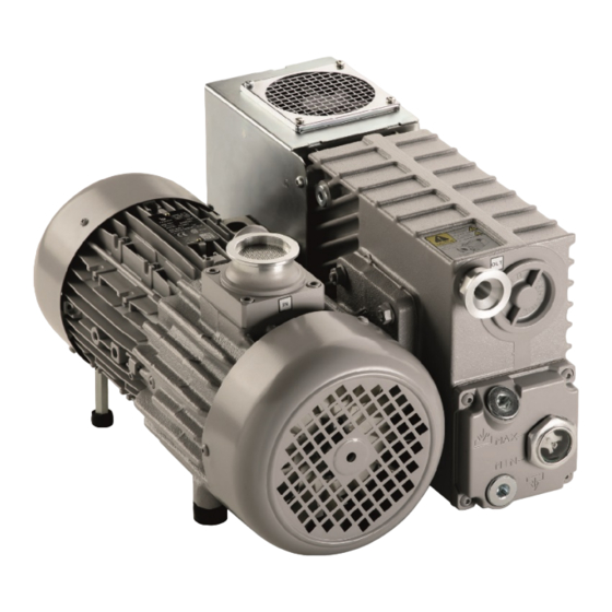
Technical Information Section I Section I Technical Description The MS40+ Single Stage Rotary Vane Pumps are rotary vane pumps oil sealed, driven by an electrical motor. Figure 3 These vacuum pumps are suitable for pumping non corrosive gases. The main features are: all parts in direct contact with the fluid pumped are free of ... -
Page 63: Vacuum Seals
Technical Information Vacuum Seals The pump is equipped with a special anti-suckback device which automatically isolates the vacuum system when the pump stops. This avoids rises in pressure or oil flow in the vacuum system. Vacuum Seals A special feature of this pump is the low number of gaskets that are employed. -
Page 64: Technical Data
Technical Information Technical Data Technical Data The following table lists the main technical data of the MS40+ Single Stage Rotary Vane Pumps. Tab. 1 TECHNICAL DATA UNITS 9499225 9499240 9499241 PUMPING SPEED (at 5 mbar inlet pressure) 1450 ULTIMATE TOTAL PRESSURE * mbar 5x10 5x10... -
Page 65: Dimensions
Technical Information Technical Data Dimensions The following figure shows the pumps layout and dimensions: Electronic controller Outlet flange Electric motor Air filter Pumping block Oil level indicator Inlet flange Figure 4 MS40+ Single Stage Rotary Vane Pumps layout Figure 5 MS40+ Single Stage Rotary Vane Pumps dimensions MS40+ Single Stage Rotary Vane Pumps User Manual / 87-901-008-01 (H.00) 65/104... -
Page 66: Safety Precautions
Technical Information Safety Precautions Safety Precautions If the equipment is used in a manner not specified by the manufacturer, the protection provided by the equipment may be impaired. Always carry the pump by means of the ring-bolt provided. The pump must be set in position taking the upmost care in order ... - Page 67 Technical Information Transport and Installation Setting the pump in position should be performed as follows: Pump laid on the ground. There are no special instructions for this type of installation, except that the floor should be as flat as possible and suited to bear the weight of the pump (it should ideally be a concrete floor) and of any accessories mounted on it.
-
Page 68: Preliminary Operations
Technical Information Transport and Installation Preliminary Operations Before starting the pump, check for oil level.. CAUTION! Oil must be poured into the casing through the special threaded plughole and NOT through the suction line. WARNING! Take out the protective caps on the suction and exhaust flanges before doing anything else. -
Page 69: Connection To The Electric Supply
Technical Information Section II Section II Connection to the Electric Supply It is recommended to connect the pump to the power supply through a dedicated CAUTION! safety switch on the main electrical panel of the installation, or in proximity of the power supply connection point. - Page 70 Technical Information Inlet and exhaust connections After switching off the pump using the main switch, wait at least 10 s before NOTE switching it back on. If rigid piping is used, it is good practice to use a flexible joint in order to avoid NOTE undue forcing of the connection on the pump.
-
Page 71: Starting And Running The Pump
Technical Information Starting and Running the Pump Starting and Running the Pump WARNING! The pump is designed for operation with neutral or non-corrosive fluids. It is absolutely forbidden to use potentially explosive or flammable substances. If the pump is started with cold oil, initially more than normal noise will be NOTE heard;... -
Page 72: Stopping The Pump
Technical Information Stopping the Pump Stopping the Pump There are no special procedures for switching the pump off. To switch the pump off, act on the mains switch. It's recommended not to disconnect the power cord from the mains supply. When the pump is stopped, the anti-suckback device makes it possible to maintain vacuum in the vessel connected on the inlet flange of the pump. -
Page 73: Warning Notes
Technical Information Warning Notes Warning Notes Death may result from contact with high voltages. Always take extreme care and observe the accident prevention regulations in force. Always disconnect the power cord to the pump before maintenance work. Place a special warning signs over the power supply breaker switch: MACHINE UNDERGOING MAINTENANCE - DO NOT POWER ON. - Page 74 Technical Information Warning Notes Do not wear any objects that may become entangled in the mechanisms and/or act as conductors (chains, bracelets, etc.). Ensure that the tools to be used are in perfect working condition and have insulating grips, where necessary. Check that the insulating material of the cables and that the conductors of the test equipment do not show any signs of damage.
-
Page 75: Caution Notes
Technical Information Caution Notes Caution Notes Before putting the pump back into operation after a breakdown, inspect it and check carefully for any other signs of damage. Use only tools that are in perfect working order and specially designed for the job; use of inappropriate or ineffective tools may cause serious damage. -
Page 76: Maintenance Actions
Technical Information Maintenance Actions Maintenance Actions SCHEDULED MAINTENANCE: Maintaining the nominal state of operation. Tab. 2 Oil level checking Daily (before every starting) Oil change 8.000 hours (light applications) Anti such-back valve checking 6 months Fan cover cleaning 6 months The scheduled maintenance for oil change is supported by an automatic timer NOTE provided by the electronic controller (available only on controllers equipped with... - Page 77 take the necessary action, where appropriate. For all problems arising, or to order spare parts, refer to our service department. Agilent Technologies Italia S.p.A. Vacuum Products Division Via F.lli Varian 54 10040 Leini, (Torino) – Italy Tel.: +39 011 997 9111 Fax: +39 011 997 9350...
-
Page 78: Oil And Filter Cartridge Replacement Procedures
Technical Information Oil and Filter Cartridge Replacement Procedures Oil and Filter Cartridge Replacement Procedures Oil Change Procedure Place a tank for waste oil under the oil drain plug. Fill oil cap Oil drain Cap Figure 6 Unscrew slowly the oil drain cap rotating it anti-clock wise using a 10mm hex key. -
Page 79: Filter Cartridge Replacement Procedure
Technical Information Oil and Filter Cartridge Replacement Procedures Open the fill oil cap using a 10 mm hex key and add AVF 60 Gold oil until reaching the maximum level on the sight glass. Close the oil fill cap tight. Replace the cartridge filter as per following slide. -
Page 80: Lubricants
Technical Information Lubricants Lubricants It will be readily understood how important adequate lubrication is to high technology pumps like the Agilent vacuum pumps. Correct use of appropriate lubricants makes a significant contribution to achieving best performance and warding off defects. When handling lubricants, the following sanitary protection measures should be observed at all times: Avoid prolonged, excessive or repeated contact of the skin with... - Page 81 Technical Information Lubricants These precisely distilled fluids (100 % solvent refined neutral paraffinic oil) deliver lower base pressure capability, faster pump- down cycles, and reduced maintenance requirements on both the pump and the fluid. It is absolutely necessary to continue using the lubricants initially used to fill the tank.
-
Page 82: Avf 60 Gold Oil Description
Technical Information Lubricants AVF 60 Gold Oil Description AVF 60 Gold oil have superior features; Reduced deposits, thanks to the absence of heavy metals (ashless); Odorless; Exceptional lubricating properties and protection against the most common solvents, and high oxidation resistance; High anti-emulsifying power with water;... -
Page 83: Pump Electronic Controller
Technical Information Pump Electronic Controller Pump Electronic Controller J1 Serial P1 I/0 Status LED Mains Switch Figure 8 Technical Specifications Input voltage: 200V-240V 50/60 Hz Max input power: 1200 VA Maximum ambient temperature: 40 °C Ingress protection level: IP 20 ... - Page 84 Technical Information Pump Electronic Controller CE mark: Tab. 4 EN55011 cat “B” EN61000-4-5 EN61000-3-2 RF EN61000-4-6 EN61000-3-3 EN61000-4-8 ESD EN61000-4-2 EN61000-4-11 EN61000-4-3 EN61010-1 EN6100-4-4 CSA mark: EN61010-1, Installation category II, pollution degree 2 EN60950 Use the Retention Spring to secure the mains cable into the IEC320 socket. NOTE MS40+ Single Stage Rotary Vane Pumps User Manual / 87-901-008-01 (H.00) 84/104...
-
Page 85: Input/Output Communications
Technical Information Pump Electronic Controller Input/Output Communications P1 – I/O Tab. 5 PIN N. SIGNAL NAME IN / OUT Interlock Status (N.O. relay contact) Speed setting (0-10V) Oil level (relay contact) Start command (24V-) Ground Interlock Status (N.O. relay contact) Oil level (relay contact) Start command (24+) Interlock: N.O. - Page 86 Technical Information Pump Electronic Controller Figure 9 Oil level: N.O. Relay contact – It is open as soon as the oil level comes down under the minimum level. Start/stop: If the inverter is managed by remote port it manage ...
-
Page 87: Rs 232/Rs 485 Communication Description
Technical Information RS 232/RS 485 Communication Description RS 232/RS 485 Communication Description Both the RS 232 and the RS 485 interfaces are available on the connector J2 J1 – Serial Port Tab. 6 PIN N. SIGNAL NAME + 5 V out TX (RS232) RX (RS232) Spare... -
Page 88: Window Protocol Description
Technical Information RS 232/RS 485 Communication Description Window Protocol Description Communication Format The communication protocol is a MASTER/SLAVE type where: 8 data bit no parity 1 stop bit baud rate: 600/1200/2400/4800/9600/19200/38400 programmable Communication Protocol The communication protocol is a MASTER/SLAVE type where: Host = MASTER ... - Page 89 Technical Information RS 232/RS 485 Communication Description Tab. 7 Data Type Field Length Valid Characters Logic (L) ‘0’ = OFF ‘1’ = ON Numeric (N) ‘-‘, ‘.’, ‘0’ . . . ‘9’ right justified with ‘0’ Alphanumeric (A) from blank to ‘_’ (ASCII) <ETX>...
-
Page 90: Examples
Technical Information RS 232/RS 485 Communication Description Type Length Value Description Out of Range 1 byte (0x34) the value expressed during a write command is out of the range value of the specified window Win Disabled 1 byte (0x35) the specified window is Read Only or temporarily disabled (for example you can’t write the Soft Start when the Pump is running) -
Page 91: Window Meanings
Technical Information RS 232/RS 485 Communication Description Source: Pump Destination: PC ADDR Command: READ PUMP STATUS Source: PC Destination: Pump (with address = 3) ADDR WINDOW Source: Pump (with address = 3 in stop status) Destination: PC ADDR WINDOW DATA (STATUS) Window Meanings Tab. - Page 92 Technical Information RS 232/RS 485 Communication Description TYPE DESCRIPTION ERROR CODE: 128: Rotor blocked; 64: shortcircuit; 32: Undervoltage/Overvoltage; 16: Motor overtemp; 8: Verify line; 4: Controller overtemp; 2: Bus Undervoltage; 1: overcurrent OUTPUT FREQUENCY [rpm] CONTROLLER TEMPERATURE [°C] POWER SUPPLY TEMPERATURE [°C] OIL LEVEL (0=level ok;...
-
Page 93: Operational Limits
Technical Information RS 232/RS 485 Communication Description Operational Limits Tab. 10 INPUT VOLTAGE (V) CONTROLLER STATUS 200 – 264 Operative with full performance 180 – 200 Operative with reduced performance < 180 or > 264 Non operative condition Status LED Tab. -
Page 94: Troubleshooting
Technical Information Troubleshooting Troubleshooting Tab. 12 ERROR FAIL MEANING POSSIBLE ACTIONS CODE CAUSES Overcurrent Required current Reversed inlet Check that pump inlet port is from the motor over and outlet connected to the instrument and that the current limit. connections. pump exhaust is connected to the exhaust line. - Page 95 Technical Information Troubleshooting ERROR FAIL MEANING POSSIBLE ACTIONS CODE CAUSES Motor Temperature Occluded motor Check if the grids are plugged by overtemp sensor inside the and pump grids. external elements (sheets of paper, motor unit over foam of the packaging, dust, etc.) and the temperature unplug them.
- Page 96 Technical Information Troubleshooting MS40+ ambient temperature limit 40°C To reset the errors described above, you must switch off the pump from the main supply button. Before switching on again the pump from the same button, you must wait at least 10 seconds, but it is strongly recommended to wait about 10 minutes if the pump is hot.
-
Page 97: Electronic Self-Test
Technical Information Troubleshooting Electronic Self-Test When you switch the pump on with the main On/Off switch the pump doesn’t start immediately but it starts only after few seconds. This test time isn’t required if the pump is already powered as when it is operated in remote or serial mode. -
Page 98: Accessories
Technical Information Accessories Accessories Tab. 13 PART NUMBER DESCRIPTION 9499201 MS40+ Exhaust filter 9499202 MS40+ 1 Litre Oil Tank 9499203 Maintenance kit 9499396 Power cable EU 9499400 208Vac US Power cable 9499398 Power cable UK 9499399 Power cable IEC320 9699883 A-PLUS Navigator SW (w/serial cable) MS40+ Single Stage Rotary Vane Pumps User Manual / 87-901-008-01 (H.00) 98/104... - Page 99 Vacuum Products Division Dear Customer, Thank you for purchasing an Agilent vacuum product. At Agilent Vacuum Products Division we make every effort to ensure that you will be satisfied with the product and/or service you have purchased. As part of our Continuous Improvement effort, we ask that you report to us any problem you may have had with the purchase or operation of our products.
- Page 100 CUSTOMER REQUEST FOR CORRECTIVE / PREVENTIVE / IMPROVEMENT ACTION AGILENT VACUUM PRODUCTS DIVISION TORINO – QUALITY ASSURANCE FAX N°: XXXX‐011‐9979350 ADDRESS: AGILENT TECHNOLOGIES ITALIA S.p.A. – Vacuum Products Division – Via F.lli Varian, 54 – 10040 Leinì (TO) – Italy E‐MAIL: vpd‐qualityassurance_pdl‐ext@agilent.com NAME...
- Page 101 Please follow these instructions whenever one of our products needs to be returned. Complete the attached Request for Return form and send it to Agilent Technologies (see below), taking particular care to include the completed Health and Safety declaration Section. No work can be started on your unit until we receive a completed copy of this form.
- Page 102 Terms and conditions TERMS AND CONDITIONS Please read the terms and conditions below as they apply to all returns and are in addition to the Agilent Technologies Vacuum Product Division – Products and Services Terms of Sale. Unless otherwise pre-negotiated, customer is responsible for the freight charges for the returning product.
- Page 103 Vacuum Products Division Request for Return Form Customer information Company : Contact Name: Address: Tel: Fax: Email: Equipment Product description Agilent PartNo Agilent Serial No Original Purchasing Reference Failure description Type of process (for which the equipment was used) Type of return Non Billable Billable New PO # (hard copy must be submitted with this form): ______________________________________...
- Page 104 Request for Return Form United States India (Sales) India (Service) Agilent Technologies Agilent Technologies India Pvt. Ltd. Agilent Technologies India Pvt. Ltd. 121 Hartwell Avenue Unit Nos 110- 116, & Part of 101 & 109 C-Block, RMZ Centennial Plot Number- 8A, 8B, 8C,...