Table of Contents
Advertisement
Quick Links
AD DeltaDome
1
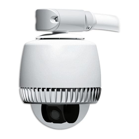
Outdoor Housing
ADODHCL with Clear Bubble
ADODHSM with Smoked Bubble
Figure 1
Mounting
Structure
Bubble
Assembly
Parts Supplied
Housing assembly
Bubble assembly
Tamperproof drive (supplied with bubble)
Install kit 0351-1519-01
Purchase or Supply Separately
Plumber's Teflon tape
Male BNC connector
Power, data, and alarm cables
Tools Required
1/4" fixed-handle nut driver for Torx bit
Wire cutters and strippers
Razor blade or scissors
3mm Allen wrench (supplied)
1-1/8" open-ended wrench
8000-2616-04, Rev. B (20 pages)
Installation and Service Guide
Housing
Assembly
Contents
About the Outdoor Housing................................... 2
Data Cable Requirements ..................................... 2
Power Cable Requirements .................................. 2
Power-Up Routine ................................................. 2
Synchronizing Domes............................................ 2
Warnings and Cautions......................................... 3
Procedure.............................................................. 5
Preparing the Housing for Attachment............... 5
Outdoor Mounting Structure............................... 6
PC Board Setup ................................................. 8
Eyeball Assembly............................................. 10
Bubble Assembly ............................................. 12
to Mounting Structure....................................... 12
Troubleshooting Outdoor Domes ........................ 13
Ordering Parts ..................................................... 16
Specifications ...................................................... 18
Declarations ........................................................ 18
About this Guide
This guide explains how to install ADODHCL and
ADODHSM outdoor housings. It does not explain
how to install the outdoor mounting structure to
which the housing is attached. For this information,
see information shipped with the structure.
DeltaDome, American Dynamics, and the AD logo are
trademarks of American Dynamics Corporation. Other
product names (if any) mentioned herein may be trademarks
or registered trademarks of other companies.
No part of this guide may be reproduced in any form without
written permission from American Dynamics Corporation.
© Copyright 1998. All rights reserved.
MDR 9/98
AD DeltaDome Outdoor Housing
1
Advertisement
Table of Contents

Related Manuals for American Dynamics ADODHCL


Summary of Contents for American Dynamics ADODHCL
-
Page 1: Table Of Contents
Specifications ... 18 Declarations ... 18 About this Guide This guide explains how to install ADODHCL and ADODHSM outdoor housings. It does not explain how to install the outdoor mounting structure to which the housing is attached. For this information, see information shipped with the structure. -
Page 2: About The Outdoor Housing
About the Outdoor Housing The ADODH outdoor housing (Figure 1) is used to attach the DeltaDome programmable surveillance camera to an outdoor mounting structure. Note: This guide assumes that a mounting structure is in place and that data and power cables have been pulled to the installation site. -
Page 3: Warnings And Cautions
Begrenzung mit einer maximalen Sicherung von 3,3 A gemäß Abschnitt 2.11 der IEC950 und 250 VA maximaler Verfügbarkeit. Das Netzteil kann über American Dynamics oder eine andere Quelle bezogen werden, wobei der Anbieter den Nachweis der Konformität bereitstellen sollte. Dies ist zur Gewährleistung der elektrischen Sicherheit... - Page 4 CAUTIONS You should have two boxes: one for the outdoor housing, the other for the bubble assembly. Protect the bubble assembly by leaving it in its box until you are ready to install it. Do not run data and power cables adjacent to or in the same conduit as line voltage mains power.
-
Page 5: Procedure
Procedure Note: Letters in brackets [ ] refer to items in Kit 0351-1519-01, which includes: Elbow, 1-1/2" NPT Connector, Plug, 3-Position Tubing, Heatshrink, .625ID .25' Thumb Nut, M3 Setscrew, M6x8 Allen Wrench, 3 mm Bushing, .37-.50" Cord Strain Relief, .37-.50" Cord, Blue Bushing, .50-.62"... -
Page 6: Attaching The Housing To The Outdoor Mounting Structure
Attaching the Housing to the Outdoor Mounting Structure Refer to Figure 4 while performing the following steps. WARNING! Turn power off. Turn power off at the source before beginning this procedure. 1. If a “Street L” pipe is attached to pipe of mounting structure, remove it. - Page 7 7. Verify cable length (Figure 7). Once housing is completely threaded in place, ends of composite cable wires should hang 3cm (1") below bottom of housing. Figure 7. Cable length below installed housing Wires should hang 3cm (1") below housing. 8.
-
Page 8: Pc Board Setup
PC Board Setup WARNING! Turn power off. Turn off power at the source before beginning this procedure. CAUTION: Hold environmental PC board by its edges to protect it from static electricity. Do not remove its dust cover. CAUTION: Connectors on PC board can be easily broken! Use a 2.5mm (0.1") slotted screwdriver. - Page 9 6. Connect relay output, if used, to connector P3 on PC board. Color Description Normally Open (3.5mA sink) Common Normally Closed 7. Connect remaining cables to PC board: Heater cable to connector P2 Fan cable to connector P5 3-pin ac plug to connector P7. 8.
-
Page 10: Attaching The Housing And Eyeball Assembly
10. Check LEDs on environmental board to verify power and data are reaching outdoor housing (Figure 12). a. Press and hold switch SW2 and observe green (ac power) and yellow (comm.) LEDs. Green LED glows steadily and yellow LED glows steadily (RS422) or blinks (SensorNet). - Page 11 2. Set dome address (Figure 14). Recessed at top of housing and eyeball assembly are three rotary address switches. Protocol address ranges are shown below. Set switches from most significant bit (MSB) to least significant bit (LSB). For example: For address 166, set SW3 to 1, SW2 to 6, and SW1 to 6.
-
Page 12: Attaching The Trim Ring/Bubble Assembly
Attaching the Trim Ring/ Bubble Assembly Refer to Figure 16. 1. Remove bubble assembly from package and ensure bubble is clean and free of debris. 2. Attach coiled lanyard from bubble to outdoor housing. Attach lanyard to threaded stud on housing using thumbnut [d]. -
Page 13: Troubleshooting Outdoor Domes
Troubleshooting Outdoor Domes Perform the following procedures if one of the following symptoms occur: Dome does not respond to commands Fans do not turn Picture grainy or discolored Poor video Ice forms on bubble. Dome Does Not Respond to Commands Follow steps until the problem is corrected. - Page 14 SensorNet Data Connections Color Designation — Not used. Brown SensorNet (unshielded) Yellow SensorNet (unshielded) CAUTION: Screws on connector P1 are delicate. DO NOT over tighten them! Use a 2.5mm (0.1") slotted screwdriver. Wider blade widths can damage connectors. 4. Check fans. Are fans on? YES: Continue.
- Page 15 Picture Grainy or Discolored Check the fans. If they are not turning, the camera dome may be overheating. See “Dome Does Not Respond to Commands” on page 14. Poor or No Video See “Dome Does Not Respond to Commands” on page 13.
-
Page 16: Ordering Parts
Ordering Parts This section helps you to identify parts that make up the outdoor housing assembly. See table opposite and Figure 18 for parts breakdown. Note: Although all parts are shown, only parts shown in bold can be ordered: Clear bubble assembly 0400-0928-01 Smoked bubble assembly 0400-0928-02 Fan/Heater assembly 0500-8023-01 Environmental board 0301-0949-01... - Page 17 Figure 18. Outdoor housing assembly (only parts shown in boxes can be ordered) AD DELTADOME OUTDOOR HOUSING 8000-2616-04, Rev. B INSTALLATION AND SERVICE GUIDE...
-
Page 18: Specifications
American Dynamics Corporation to notify any person of such revision or changes. LIMITED RIGHTS NOTICE: For units of the Department of... - Page 19 AD DELTADOME OUTDOOR HOUSING INSTALLATION AND SERVICE GUIDE 8000-2616-04, Rev. B...
- Page 20 American Dynamics Sensormatic CCTV Systems Division One Blue Hill Plaza Pearl River, NY 10965 Technical Support Center 1-800-442-2225 Business (914) 624-7600 AD DELTADOME OUTDOOR HOUSING INSTALLATION AND SERVICE GUIDE 8000-2616-04, REV. B...