Dell PowerEdge R320 Planning, Installation And Service Manual
Hide thumbs
Also See for PowerEdge R320:
- Owner's manual (143 pages) ,
- Technical manual (51 pages) ,
- Getting started manual (11 pages)

Related Manuals for Dell PowerEdge R320


Summary of Contents for Dell PowerEdge R320
- Page 1 R320 Honeywell Server Planning, Installation and Service Guide HWDOC-X238-en-A August 2020...
- Page 2 Disclaimer This document contains Honeywell proprietary information. Information contained herein is to be used solely for the purpose submitted, and no part of this document or its contents shall be reproduced, published, or disclosed to a third party without the express permission of Honeywell International Sàrl. While this information is presented in good faith and believed to be accurate, Honeywell disclaims the implied warranties of merchantability and fitness for a purpose and makes no express warranties except as may be stated in its written agreement with and for its customer.
-
Page 3: Table Of Contents
2.1.1 Software requirement 2.1.2 BIOS configuration 2.2 Description 2.2.1 Honeywell server model number 2.2.2 Electronics configuration 2.2.3 Electronics module 2.2.4 Standard features of Dell R320 2.2.5 Slots configuration 2.2.6 Optional features 2.2.7 Power cords 2.3 Platform information 2.3.1 Honeywell documentation 2.3.2 Dell documentation... - Page 4 3.4.1 Honeywell server back panel connections 3.4.2 Installing the server 3.4.3 Connecting the cables 3.4.4 Install air duct baffles and blank panel front covers in cabinet 3.5 Starting the server 3.5.1 Turning on the power 3.5.2 Configuring RAID in Dell R320 server - 4 -...
- Page 5 3.5.3 Starting the TDC emulator services 3.5.4 Checking the LCNP4e/LCNP4e2 status Chapter 4 - Operation 4.1 Server overview 4.1.1 Front view of Dell R320 server 4.1.2 Rear view of Dell R320 server 4.2 Network connections 4.2.1 Ethernet network 4.2.2 LCN cables 4.2.3 LCN connections...
- Page 6 5.8.1 Integrated Dell Remote Access Controller 6 (iDRAC6) issue - 6 -...
-
Page 7: Chapter 1 - About This Document
Honeywell factory or has manuals dedicated to its installation and service. This server is not a standard Dell model and you cannot order it independently from Dell. - Page 8 Chapter 1 - About this Document Publication Content Type (EPDOC-X478-en-511A) Experion LCN Planning, ELCN system planning, hardware/software Installation, and Service Guide installation, servicing/troubleshooting (HWDOC-X479-en-E) Experion LCN Specification General ELCN technical specifications (ELCN03) Fault Tolerant Ethernet FTE system installation, servicing/troubleshooting Installation and Service Guide (EPDOC-XX36-en511A) Universal Embedded General UEA planning, installation, and service...
-
Page 9: Revision History
Chapter 1 - About this Document Publication Content Type Experion Network Best Best practices for planning the installation of Experion Practices (WP-07-02-ENG) FTE networks, and connecting them into plant IT networks. Experion R510 Software Describes Experion R510 features/enhancements, Change Notice (EPDOC- overall product, release interoperabilities, system X166-en-511A) dependencies, problem resolutions, known issues,... -
Page 10: Chapter 2 - Planning
Dell. The Technical Assistance Center (TAC) is well trained and supports Honeywell platforms. Use of any other server including a similar Dell model, is considered a project special and its TAC support is limited according to the services policy. -
Page 11: Bios Configuration
AM ride-through feature will not work on E-APP nodes and ACE-T nodes. 2.1.2 BIOS configuration The BIOS version for the server depends on the Tab numbers. The Tab number for Dell R320 is as follows: Tab 51155519-100 with BIOS version 1.3.5 Honeywell [1.0.0.]. -
Page 12: Electronics Configuration
Microsoft windows Server 2016,64Bit COA COAS16 2.2.2 Electronics configuration The Dell R320-based server is approved for installation in the Honeywell 1000 mm deep LCN cabinet only, using the Sliding ReadyRail II kit included in the purchase of the server. 2.2.3 Electronics module The tables in this section provides the electronics module for the Honeywell-based Dell R320 server platforms, which includes MLK and pre-MLK servers. -
Page 13: Standard Features Of Dell R320
677.3 mm 19.3 KGs (42.5) 2.2.4 Standard features of Dell R320 Following are the common features of pre-MLK server: Intel Xeon E5-2430 2.20 GHz, 15M Cache / 4 GB RDIMM (2x2 GB) / 146 GB 15K RPM Serial-Attach SCSI 6 Gbps 2.5in Hot plug Hard Drive (QTY 4)/H710 mini Controller (RAID 5 configuration) 1 serial, 1Video, 2 USB V2.0, 2 RJ45, 1 ID push button with blue/amber LED. -
Page 14: Optional Features
A Local Control Network Processor (LCNP) board and LCN Media Access Unit (MAU) are no longer used if the Server has been upgraded to be an ELCN node. Platform information Honeywell documentation Dell documentation 2.3.1 Honeywell documentation The following table lists the Honeywell publications that may be useful when installing or operating your system. -
Page 15: Dell Documentation
Chapter 2 - Planning 2.3.2 Dell documentation The following table lists the Dell publications that may be useful when installing or operating the system. Is available Publication Contains information about with Readme files Last-minute updates about technical changes to The drivers... -
Page 16: Lcn Node Slot Requirements
Memory configuration for Dell R320 Standard memory for Dell R320 MLK server is 8GB (2x4GB) RDIMM, 1600MHz or faster and it must be installed in pairs. The label on the outside of the shipping container shall identify the capacity of the memory installed. -
Page 17: 4Gb, Consisting Of Two 2Gb Rdimm For Pre-Mlk Servers
Chapter 2 - Planning Honeywell model number Description MZ-PCEM15 2GB RDIMM, 1333 MHz MZ-PCEM20 4GB ECC 1600MHZ MEM EXP (1x4GB) RDM or better Note the following: Non-MLK server uses processor 1 with Intel Xeon E5-2430 2.20GHz. MLK server uses processor 1 with Intel Xeon E5-2430V2 2.50GHz. 4GB, consisting of two 2GB RDIMM for Pre-MLK servers 8GB, consisting of four 2GB RDIMM or two 4GB RIDMM for Pre-MLK servers 8GB, consisting of two 4GB RIDMM for MLK servers... -
Page 18: 8Gb, Consisting Of Two 4Gb Ridmm For Mlk Servers
Chapter 2 - Planning In order to support R50x.x release, customer needs to remove existing 2GB memory modules and use 4 Modules of MZ-PCEM20 and make server to 16GB, please refer table 2.6.3 for more details. 2.6.3 8GB, consisting of two 4GB RIDMM for MLK servers The following table provides memory configurations layout for 8GB, consisting of two 4GB RIDMM for MLK servers. -
Page 19: Pcie Slots
Chapter 2 - Planning Microprocessor Non-MLK server: Intel Xeon E5-2430 2.20 GHz, 15M Cache, 7.2GT/s QPI, Turbo, 6C, 95 W MLK server: Intel Xeon E5-2430V2 2.50 GHz, 15M Cache, 7.2GT/s QPI, Turbo, 6C, 80 W Level 2 Cache 1 MB Level 3 Cache 15 MB Chipset... -
Page 20: Network Interface
Chapter 2 - Planning 2.7.7 Network interface Adapter type Broadcom® 5720 Dual Port 1Gb LOM 2.7.8 Power The following provides the specifications for DC power supply. Wattage Energy Smart: Dual Hot Plug Power Supplies 350W - 20 -... -
Page 21: Environmental
Chapter 2 - Planning 2.7.9 Environmental - 21 -... - Page 22 Chapter 2 - Planning Operating temperature +10° to +35° C (50° to 95° F) with a maximum temperature gradation of 10° per hour . Note: for Altitudes above 2950 feet , the maximum operating temperature is de-rated 1°F/550ft. All temperature ratings shown are for sea level. An altitude de-rating of 1°C per 300 m (1.8°F per 1,000 ft) to 3048 m (10,000 ft) is applicable.
-
Page 23: Physical - Form Factor
Maximum vibration Operating 0.26 Grms at 5 Hz to 350 Hz in all orientations Storage 1.87 Grms at 10 Hz to 500 Hz for 15 minutes (all six sides tested by Dell) 2.7.13 Shock Operating Half sine shock in all operational orientations of 31G +/– 5% with a pulse duration of 2.6 ms +/–... -
Page 24: Altitude
Chapter 2 - Planning 2.7.14 Altitude Operating -15.2 to 3048 m (-50 to 10,000 ft) Note: For altitudes above 2950 feet (899.16 meters), the maximum operating temperature is derated 1°F/550 ft. (that is. 1°F /167.64 meters that is -17.22°c/167.64 meters) Storage -15.2 to 12,000 m (-50 to 39,370 ft) 2.7.15... -
Page 25: Hard Disk Drive Specifications
Hard disk drive specifications The Honeywell-based Dell R320 has four hard disk drive bays. It uses four 146 GB or 300 GB SAS 2.5” hard drives for RAID-5 (distributed parity). A 5th 146 GB or 300 GB 2.5” 15K RPM SAS HDD hot spare is available and must be bought separately (P/N MZ-PCEH01). -
Page 26: Video Cable
2.7.24 Video cable Correct system startup and operation of the Honeywell-based Dell R320 server platform requires industry standard VESA DDC interface to the monitor. If either a monitor or video cable that does not support DDC is attached to the server platform, the display generator defaults to a resolution, which precludes communication with the system software and stops startup. -
Page 27: Safety Compliance
Chapter 2 - Planning Electrical cables, which are routed external to the equipment, must be fully shielded cables (360 degree metallic shielding), to comply with the above EMC standards. 2.8.2 Safety compliance The following are the product safety compliance. CSA C22.2 No. 1010.1-92 (R1999) and 1010.1B-97 (R2001) Am. 2 IEC 61010-1, 2001, 2nd edition ATTENTION In the above referenced standards is a “Normative Reference”... -
Page 28: Safety Compliance
Chapter 2 - Planning Examples: P = 10 Watts, D > 0.949 meters P = 5 Watts, D > 0.671 meters P = 1 Watt, D > 0.300 meters Electrical cables, which are routed external to the equipment, must be fully shielded cables (360 degree metallic shielding), to comply with the above EMC standards. -
Page 29: Chapter 3 - Installation
CHAPTER NSTALLATION This section describes the procedures for installing the platform and cabling the server in a 1-meter deep Honeywell cabinet. Tasks for installing the server Power and grounding requirements Cabinet spacing requirements Installing the server and connecting the cables Starting the server Tasks for installing the server The following table lists the major platform installation tasks. -
Page 30: Cabinet Spacing Requirements
Cabinet spacing requirements Starting from the bottom of the cabinet, seven Dell R320 servers are allowed to be mounted on the first 15U of the rack space. This is done due to the thermal constraints. A 1U high spaced front and side air baffles must be installed immediately above each Dell R320 server. -
Page 31: Installing The Server And Connecting The Cables
Chapter 3 - Installation Height option Part Part number Tab number Blank front panel 51201248 -100 Air duct baffle 51303521 -100 Blank front panel 51201248 -200 Air duct baffle 51303521 -200 Blank front panel 51201248 -300 Air duct baffle 51303521 -300 Blank front panel 51201248... -
Page 32: Connecting The Cables
Chapter 3 - Installation 1. From the front of the cabinet, open the door to access the mounting rails. 2. Fully extend the right and left Sliding Ready Rails (pre-installed in the Honeywell factory). 3. Lower the server into the J-shaped slots on each slide, starting with the slot that is closest to the cabinet. -
Page 33: Install Air Duct Baffles And Blank Panel Front Covers In Cabinet
Chapter 3 - Installation 5. If necessary, refer to the section Install air duct baffles and blank panel front covers in cabinet. ATTENTION Any unused rack mount space must have an air duct baffle and blank front panel installed. 6. To complete the installation, turn on the server. 3.4.4 Install air duct baffles and blank panel front covers in cabinet Air duct baffles and blank panel front covers ensure that the airflow within the cabinet allows proper... - Page 34 Chapter 3 - Installation To install air duct baffles and blank panel front covers in cabinet 1. Place the air duct baffle inside the cabinet with the bent tab resting along the front of the right cabinet rail. Figure 3.2 Installation of Air Duct Baffle and Blank Panel Front Cover 2.
-
Page 35: Starting The Server
2. Wait for the power light to become solid green. ATTENTION If the power light does not become solid green, refer to the Troubleshooting section in the Dell™ PowerEdge™ R320 Systems Owner’s Manual. 3.5.2 Configuring RAID in Dell R320 server Perform the following steps to configure a new virtual disk of RAID5 four physical disks and one hot spare. -
Page 36: Starting The Tdc Emulator Services
Chapter 3 - Installation 8. Select Create New VD and press ENTER. The Create New VD screen appears. The cursor is on the RAID Level option. 9. Press ENTER to display the RAID levels. 10. Select a RAID-5 using the arrow keys, and then press ENTER. 11. - Page 37 Chapter 3 - Installation To check the LCNP4e/LCNP4e2 status 1. Choose Start > Programs > Honeywell TPS > LCNP Status. 2. Verify that the LCNP status indicates Passed Self Test and the circle is green. 3. Verify that the TPN Address appears in the LEDs field of the LCNP Status display, after the Board 0 is configured for the node’s TPN address.
-
Page 38: Chapter 4 - Operation
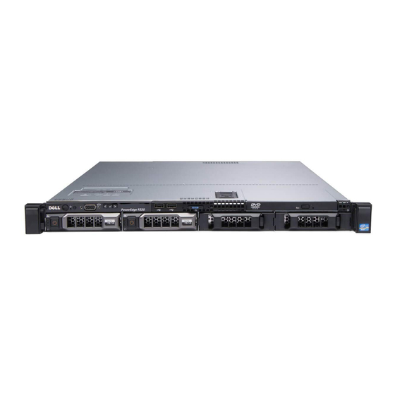
Rear view of Dell R320 server 4.1.1 Front view of Dell R320 server The following image illustrates the front view of the Dell R320 server. These servers are provided with eight 2.5 inch hard-drive chassis. Figure 4.1 Front View of Dell R430 Server The following are the explanation for the items in the images. -
Page 39: Network Connections
Chapter 4 - Operation Figure 4.2 Rear View of Dell R430 Server The following are the explanation for the items in the image. 1. PCIe expansion card slot 1 2. vFlash media card slot 3. iDRAC port (optional) 4. Serial connector 5. -
Page 40: Lcn Connections
This is consistent with the current LCN standard procedure. The Honeywell server platform uses only a digital system clock. When the Dell R320 platform is added to an existing system that contains nodes running analog clocks that system must have at least two (2) KxLCN boards for analog/digital clock translation. -
Page 41: Controlnet Network
Chapter 4 - Operation 4.2.6 ControlNet Network A ControlNet Network is a single coaxial trunk cable broken up into segments interconnected by links. Node Connections to the network are created through a Tap and drop cable. Repeaters are used to link segments together and for changes in media from coax to fiber optic. -
Page 42: Configuring Controlnet Interface Card
Chapter 4 - Operation ATTENTION TC-PCIC02: Controlnet Network interface can be connected toDell PowerEdge R320 serverusing Magma PCIe to PCI converter. For more information on “How to connect using Magma Converter” refer to the Magma PE3R Installation Instructions available at the following Honeywell Process Solutions support website. -
Page 43: Chapter 5 - Servicing
Server has been upgraded to be an ELCN node. Servicing the LCNP4e/LCNP4e2 Servicing the hard disk drives and power supply Adding additional memory in Dell R320 Installing hot spare hard drive Servicing Honeywell options Verifying correct BIOS settings... - Page 44 Chapter 5 - Servicing To replace the LCNP4E/LCNP4e2 board NOTE If upgrading to an ELCN node, perform Steps 1 thru 7 to remove the LCNP4 board. 1. Shut down the computer. 2. Remove the power cords from the rear end of the server and wait for 20 seconds. 3.
- Page 45 Chapter 5 - Servicing 6. Remove the metal shield adjacent to the LCNP4E/LCNP4e2 card in PCIe slot 2. 7. While wearing a grounded ESD wrist strap, grasp the LCNP4E/LCNP4e2 card at the corners and gently remove the existing card from PCIe slot 2. 8.
-
Page 46: Modifying Vga Port Saver
Chapter 5 - Servicing 9. Replace the card retainers (blue plastic notch) to lock the inserted LCNP4E/LCNP4e2 board in position. 10. Replace the top cover of the server. 5.1.2 Modifying VGA port saver The VGA port saver must be modified before it is used. - 46 -... - Page 47 Chapter 5 - Servicing To modify the VGA port saver 1. Using a screwdriver Remove both screw-locks on the port saver. 2. Replace the screw-locks on the VGA Port saver so that the female end of the screw-locks faces the same direction as the VGA plug side of the connector.
-
Page 48: Servicing The Hard Disk Drives And Power Supply
You must replace only one power supply and/or hard disk drive at a time in a system that is turned on. Refer to the Dell documentation for detailed instructions on swapping the power supply and hard disk drive. -
Page 49: Adding Additional Memory In Dell R320
Chapter 5 - Servicing Publication Contains information about… Dell PowerEdge R320 Systems Owner's Manual System Overview Basic Troubleshooting Indicators, Codes, and Messages Removing and Installing Parts Jumpers and Connectors Using the System Setup Program Finding Software Solutions Running the System Diagnostics... -
Page 50: To Add Additional Memory
Chapter 5 - Servicing 5.3.2 To add additional memory 1. Remove the power cords from the rear end of the server and wait for 20 seconds. 2. Remove the top cover of the server. Figure 5.1 Removal of Top Cover 3. -
Page 51: Installing Hot Spare Hard Drive
Chapter 5 - Servicing 6. Align the edge of the memory module connector with the alignment key on the memory module socket, and insert the memory module into the socket. ATTENTION The memory module socket has an alignment key that allows you to install the memory module in the socket only in one way. -
Page 52: To Insert The Hot Spare Hard Drive
Chapter 5 - Servicing 5.4.1 To insert the hot spare hard drive 1. From the front end of the server, locate the blocking plate at the fifth bay (marked as 4). 2. Press the latches located at the ends of the blocking plate and pull the blocking plate. Figure 5.4 Pull the Blocking Plate 3. -
Page 53: Servicing Honeywell Options
Chapter 5 - Servicing ATTENTION In Dell PowerEdge R320 Server 146 GB Hard disk drives (MZ-PCEH02) are obsolete and Customer may received Replacement as 300 GB (MZ-PCEH06) Hard disk drives. These drives can be used in RAID5 array with 146 GB Hard disk drives. Usable capacity of will remain 146 GB as it will be part of Array. -
Page 54: Verifying Correct Bios Settings
2. Press F2 on the keyboard to enter the BIOS Setup. 3. Verify that the BIOS version. 5.6.2 BIOS settings for Tab 51156309-100 System information Product name Dell PowerEdge R320 server System model name R320, 001 BIOS Version 1.3.5 [Honeywell 1.0.0] System manufacturer... - Page 55 Chapter 5 - Servicing Memory information System memory size 4.0 GB or 8GB System memory type ECC DDR3 System memory speed 1333 MHz or faster System memory voltage 1.35 V Video memory 16 MB System memory testing Disabled Memory operating mode Advanced ECC Mode Node interleaving Disabled...
- Page 56 Chapter 5 - Servicing Processor 1 Family – Model – Stepping 06-0D-7 Brand [[Intel® Xeon® CPU E5 2430 0@ 2.2GHz]] Level 2 Cache 6 X 256 KB Level 3 Cache 15 MB Number of cores SATA settings Embedded SATA ATA Mode PORT A / B / C / D / F Auto Model...
- Page 57 Chapter 5 - Servicing Boot option Enable / Disable 1. Embedded SATA Port Optical Drive : SATA Optical Drive [X] 2. Hard disk C: [X] 3. Onboard Broadcom NIC Hard disk drive sequence Integrated RAID Controller 1: PERC H710 Mini (bus 01 dev 00) Integrated devices Integrated RAID Controller Enabled...
- Page 58 Chapter 5 - Servicing System profile settings System profile Performance CPU Power Management Maximum Performance Memory Frequency Maximum Performance Tubo boost Enabled Disabled C states Disabled Monitor/Mwait Enabled Memory Patrol Scrub Standard Memory refresh rate Memory Operating Voltage Auto Collaborative CPU Performance control Disabled System security Intel AES-NI...
-
Page 59: Bios Settings For Tab 51155519-200
F1/F2 Prompt on Error Enabled In System Characterization Enabled 5.6.3 BIOS settings for Tab 51155519-200 System information Product name Dell PowerEdge R320 server System model name R320, 001 BIOS Version 2.0.22 or higher Service Tag <note the service tag> System manufacturer... - Page 60 Chapter 5 - Servicing CPU information Logical processor Enabled Alternate RTID Disabled Virtualization technology Enabled Adjacent cache prefetcher Enabled Hardware prefetcher Enabled DCU Steamer Prefetcher Enabled DCU IP Prefetcher Enabled Execute Disable Enabled Logical Processor Idling Disabled Number of Cores per processor Processor 64-bit Support Processor Core Speed 2.50 GHz...
- Page 61 Chapter 5 - Servicing SATA settings Embedded SATA ATA Mode PORT A / B / C / D / F Auto Model Unknown Device type Unknown device Capacity PORT E Auto Model DVD R/W model number Device type Optical drive Capacity Boot settings Boot Mode...
- Page 62 Chapter 5 - Servicing Integrated devices Integrated RAID Controller Enabled User Accessible USB Ports All Ports On Internal USB Port Embedded NIC1 and NIC2 Enabled OS Watchdog Timer Disabled I/O AT DMA Engine Disabled Embedded Video Controller Enabled SR-10V Globe Engine Disabled Memory mapped I/O above 4GB Disabled...
- Page 63 Chapter 5 - Servicing System profile settings System profile Performance CPU Power Management Maximum Performance Memory Frequency Maximum Performance Tubo boost Enabled Disabled C states Disabled Monitor/Mwait Enabled Memory Patrol Scrub Standard Memory refresh rate Memory Operating Voltage Auto Collaborative CPU Performance control Disabled System security Intel AES-NI...
-
Page 64: Exiting The Bios
331-2254 51155517-903 Mouse Optical Mouse, Two Buttons, USB, Black 331-0846 51155517-904 Hard Disk Dell 146 GB 15K 6G 2.5 SAS DP HDD 342-0427 51155517-905 Drive Dell 300 GB 15K 6G 2.5 SAS DP HDD 51155519-905 Rack mount Ready Rails Sliding Rails With Cable... -
Page 65: Troubleshooting
Chapter 5 - Servicing Troubleshooting 5.8.1 Integrated Dell Remote Access Controller 6 (iDRAC6) issue Refer to the PN2014-13 for further information about iDRAC6 issue. You must search for the PN2014- 13 at the following Honeywell Process Solutions support website. http://www.honeywellprocess.com/support... - Page 66 Notices Trademarks Experion®, PlantScape®, SafeBrowse®, TotalPlant®, and TDC 3000® are registered trademarks of Honeywell International, Inc. ControlEdge™ is a trademark of Honeywell International, Inc. OneWireless™ is a trademark of Honeywell International, Inc. Matrikon® and MatrikonOPC™ are trademarks of Matrikon International. Matrikon International is a business unit of Honeywell International, Inc.
- Page 67 For support, contact your local Honeywell Process Solutions Customer Contact Center (CCC). To find your local CCC visit the website, https://www.honeywellprocess.com/en-US/contact-us/customer- support-contacts/Pages/default.aspx. Training classes Honeywell holds technical training classes that are taught by process control systems experts. For more information about these classes, contact your Honeywell representative, or see http://www.automationcollege.com.