
Related Manuals for Dell PowerEdge R330


Summary of Contents for Dell PowerEdge R330
- Page 1 Dell PowerEdge R330 Owner's Manual Regulatory Model: E34S Series Regulatory Type: E34S001...
- Page 2 WARNING: A WARNING indicates a potential for property damage, personal injury, or death. Copyright © 2017 Dell Inc. or its subsidiaries. All rights reserved. Dell, EMC, and other trademarks are trademarks of Dell Inc. or its subsidiaries. Other trademarks may be trademarks of their respective owners.
-
Page 3: Table Of Contents
Contents 1 About your system......................9 ....................10 Supported configurations on PowerEdge R330 systems ............................ 11 Front panel features and indicators ..............................14 LCD panel features ............................15 Back panel features and indicators ................................. 16 Diagnostic indicators ........................16 Diagnostic indicators on the front panel ............................17... - Page 4 ................................44 About Boot Manager ............................... 44 Viewing Boot Manager ............................44 Boot Manager main menu ............................45 About Dell Lifecycle Controller ..............................45 Changing the boot order ............................45 Choosing the system boot mode ..........................45 Creating a system and setup password ......................46...
- Page 5 ............................52 Installing the system cover ................................54 Inside the system ................................57 Intrusion switch ............................57 Removing the intrusion switch ............................. 58 Installing the intrusion switch ................................. 58 Cooling shroud ............................. 59 Removing the cooling shroud ............................59 Installing the cooling shroud ................................
- Page 6 ..........................93 Removing the expansion card riser ..........................94 Installing the expansion card riser ............................95 Removing an expansion card ............................96 Installing an expansion card ..........................98 Removing the internal PERC card ..........................99 Installing the internal PERC card ..............................100 SD vFlash card (optional) ........................
- Page 7 ...................... 147 When to use the Embedded System Diagnostics ................147 Running the Embedded System Diagnostics from Boot Manager ............147 Running the Embedded System Diagnostics from the Dell Lifecycle Controller ............................147 System diagnostic controls 8 Jumpers and connectors....................149 ............................149 System board jumper settings ...............................
- Page 8 ..............................164 Documentation feedback ........................164 Accessing system information by using QRL...
-
Page 9: About Your System
About your system The Dell PowerEdge R330 is a single socket rack server and supports the following hardware configuration: Component Quantity Processor The server supports one processor from these product families • Intel E3-1200 v5 or v6 series • Intel Core i3 6100 series •... -
Page 10: Supported Configurations On Poweredge R330 Systems
Supported configurations on PowerEdge R330 systems Figure 1. System view with supported configurations... -
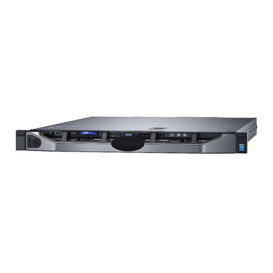
Page 11: Front Panel Features And Indicators
Front panel features and indicators Figure 2. Front panel features and indicators — four 3.5-inch hot-swappable hard drive chassis Table 1. Front panel features and indicators— four 3.5-inch hot-swappable hard drive chassis Item Indicator, button, or Icon Description connector Power-on indicator, power Enables you to know the power status of the system. - Page 12 Functions as a regular USB port or provide access to the iDRAC iDRAC managed USB port Direct features. For more information, see the iDRAC User’s Guide at Dell.com/idracmanuals. USB connector Enables you to connect USB devices to the system. The port is USB 2.0-compliant.
- Page 13 Functions as a regular USB port or provide access to the iDRAC managed USB port Direct features. For more information, see the iDRAC User’s Guide at Dell.com/idracmanuals. USB connector Enables you to connect USB devices to the system. The port is USB 2.0-compliant.
-
Page 14: Lcd Panel Features
The system's LCD panel provides system information and status and error messages to indicate if the system is operating correctly or if the system needs attention. For more information about the error messages, see the Dell Event and Error Messages Reference Guide at Dell.com/openmanagemanuals >... -
Page 15: Back Panel Features And Indicators
Figure 5. LCD panel Features Left Select Right Button Description Left Moves the cursor back in one-step increments. Select Selects the menu item highlighted by the cursor. Right Moves the cursor forward in one-step increments. During message scrolling: • Press once to increase scrolling speed •... -
Page 16: Diagnostic Indicators
Check the System Event Log or system messages for the specific issue. For more information about error • When the system is turned on. messages, see the Dell Event and Error Messages • When the system is in standby. Reference Guide at Dell.com/openmanagemanuals >... -
Page 17: Hard Drive Indicator Codes
Icon Description Condition Corrective action Hard drive The indicator flashes amber if there Check the System Event Log to determine the hard indicator is a hard drive error. drive that has an error. Run the appropriate Online Diagnostics test. Restart the system and run embedded diagnostics (ePSA). -
Page 18: Nic Indicator Codes
Hard drive NOTE: If the hard drive is in the Advanced Host Controller Interface (AHCI) mode, the status indicator (on the right side) does not turn on. Table 6. Hard drive indicator codes Drive-status indicator pattern Condition Flashes green twice per second Identifying drive or preparing for removal. -
Page 19: Internal Dual Sd Module Indicator Codes
Convention Status Condition Link indicator is amber The NIC is connected to a valid network at less than its maximum port speed. Activity indicator is flashing green Network data is being sent or received. Internal dual SD module indicator codes The Internal Dual SD module (IDSDM) provides you with a redundant SD card solution. -
Page 20: Indicator Codes For Redundant Power Supply Unit
Table 9. iDRAC Direct LED indicators Convention iDRAC Direct LED Condition indicator pattern Green Turns green for a minimum of two seconds to indicate the start and end of a file transfer. Flashing green Indicates file transfer or any operation tasks. Green and turns off Indicates that the file transfer is complete. -
Page 21: Locating Service Tag Of Your System
Alternatively, the information may be on a sticker on the chassis of the system. This information is used by Dell to route support calls to the appropriate personnel. -
Page 22: Documentation Resources
Methods to download firmware and drivers section in this document. Managing your system For information about systems management Dell.com/openmanagemanuals software offered by Dell, see the Dell OpenManage Systems Management Overview Guide. For information about setting up, using, and Dell.com/openmanagemanuals troubleshooting OpenManage, see the Dell OpenManage Server Administrator User’s Guide. - Page 23 For information about installing and using Active Dell.com/asmdocs System Manager (ASM), see the Active System Manager User’s Guide. For understanding the features of Dell Lifecycle Dell.com/idracmanuals Controller (LCC), see the Dell Lifecycle Controller User’s Guide. For information about partner programs Dell.com/...
-
Page 24: Technical Specifications
Technical specifications Chassis dimensions This section describes the physical dimensions of the system. Figure 11. Chassis dimensions of the PowerEdge R330 system Table 13. Dimensions of the Dell PowerEdge R330 system Z (with bezel) Z (without Za (with Za (without... -
Page 25: Processor Specifications
Processor specifications Processor Specification Type The PowerEdge R330 supports any one of the processors listed here: • Intel E3-1200 v5 or v6 series • Intel Core i3 6100 series • Intel Celeron G3900 series • Intel Celeron G3930 • Intel Pentium G4500 series •... -
Page 26: Power Specifications
For more information on software RAID, see the Dell PowerEdge RAID Controller (PERC) documentation at Dell.com/storagecontrollermanuals. Drive specifications Hard drives The PowerEdge R330 system supports SAS, SATA, Nearline SAS hard drives and Solid State Drives (SSDs). Drives Specification Eight hard drive Up to eight 2.5-inch, hot swappable SAS, SATA, SATA SSD, or Nearline SAS hard drives. -
Page 27: Ports And Connectors Specifications
9-pin connector, Data Terminal Equipment (DTE), 16550-compliant. VGA ports The Video Graphic Array (VGA) port enables you to connect the system to a VGA display. The PowerEdge R330 system supports two 15-pin VGA ports one each on the front and back panels. -
Page 28: Expanded Operating Temperature
• Non-redundant power supply units are not supported. Restrictions • Non Dell qualified peripheral cards and/or peripheral cards greater than 25 W are not supported. • Do not perform a cold startup below 5°C (40°F). • Enable processor performance degrade. - Page 29 Temperature Specifications Storage –40°C to 65°C (–40°F to 149°F) Continuous 10°C to 35°C (50°F to 95°F) with no direct sunlight on the equipment. operation (for altitude less than 950 m or 3117 ft) Fresh air For information on fresh air, see Expanded Operating Temperature section. Maximum 20°C/h (68°F/h) temperature...
- Page 30 Particulate Specifications contamination NOTE: Applies to data center environments only. Air filtration requirements do not apply to IT equipment designed to be used outside a data center, in environments such as an office or factory floor. NOTE: Air entering the data center must have MERV11 or MERV13 filtration. Conductive dust Air must be free of conductive dust, zinc whiskers, or other conductive particles.
-
Page 31: Initial System Setup And Configuration
Turn on the attached peripherals. iDRAC configuration The Integrated Dell Remote Access Controller (iDRAC) is designed to make system administrators more productive and improve the overall availability of Dell EMC systems. iDRAC alerts administrators to system issues, helps them perform remote system management, and reduces the need for physical access to the system. -
Page 32: Options To Install The Operating System
The default user name and password are root and calvin. You can also log in by using Single Sign-On or Smart Card. NOTE: You must have iDRAC credentials to log in to iDRAC. For more information about logging in to iDRAC and iDRAC licenses, see the latest Integrated Dell Remote Access Controller User's Guide at Dell.com/idracmanuals. - Page 33 Click Drivers & Downloads. The drivers that are applicable to your selection are displayed. Download the drivers to a USB drive, CD, or DVD.
-
Page 34: Pre-Operating System Management Applications
Pre-operating system management applications You can manage basic settings and features of a system without booting to the operating system by using the system firmware. Navigation keys The navigation keys can help you quickly access the pre-operating system management applications. Table 19. -
Page 35: System Setup Details
The iDRAC settings utility is an interface to set up and configure the iDRAC parameters by using UEFI (Unified Extensible Firmware Interface). You can enable or disable various iDRAC parameters by using the iDRAC settings utility. For more information about this utility, see Integrated Dell Remote Access Controller User’s Guide at Dell.com/idracmanuals. -
Page 36: Memory Settings Details
Option Description System Specifies the current version of the Management Engine firmware. Management Engine Version System Service Tag Specifies the system Service Tag. System Specifies the name of the system manufacturer. Manufacturer System Specifies the contact information of the system manufacturer. Manufacturer Contact Information... -
Page 37: Sata Settings Details
NOTE: This option is only available on certain stock keeping units (SKUs) of the processors. X2Apic Mode Enables or disables the X2Apic mode. Dell Controlled Controls the turbo engagement. Enable this option only when System Profile is set to Performance. Turbo NOTE: Depending on the number of installed CPUs, there may be up to four processor listings. - Page 38 Option Description Option Description Drive Type Specifies the type of drive attached to the SATA port. Capacity Specifies the total capacity of the hard drive. This field is undefined for removable media devices such as optical drives. Port B For AHCI or RAID mode, BIOS support is always enabled. Option Description Model...
-
Page 39: Boot Settings Details
Option Description Option Description Capacity Specifies the total capacity of the hard drive. This field is undefined for removable media devices such as optical drives. Boot Settings details The Boot Settings screen details are explained as follows: Option Description Boot Mode Enables you to set the boot mode of the system. -
Page 40: Integrated Devices Details
UEFI iSCSI Settings screen details You can use the iSCSI Settings screen to modify iSCSI device settings. The iSCSI Settings option is available only in the UEFI boot mode. BIOS does not control network settings in the BIOS boot mode. For BIOS boot mode, the option ROM of the network controller handles the network settings. -
Page 41: Serial Communication Details
Option Description peripheral card prevents booting into the operating system or causes delays in system startup. If the slot is disabled, both the Option ROM and UEFI drivers are disabled. Serial Communication details The Serial Communication screen details are explained as follows: Option Description Serial... -
Page 42: System Security Settings Details
Option Description Memory Frequency Sets the speed of the memory. You can select Maximum Performance, Maximum Reliability, or a specific speed. Turbo Boost Enables or disables the processor to operate in the turbo boost mode. This option is set to Enabled by default. -
Page 43: Miscellaneous Settings Details
Option Description TPM Command CAUTION: Clearing the TPM results in the loss of all keys in the TPM. The loss of TPM keys may affect booting to the operating system. Clears all the contents of the TPM. The TPM Clear option is set to No by default. Intel TXT Enables or disables the Intel Trusted Execution Technology (TXT) option. -
Page 44: About Boot Manager
Enables you to access boot menu, where you can select a one-time boot device to boot from. Menu Launch System Enables you to access System Setup. Setup Launch Lifecycle Exits the Boot Manager and invokes the Dell Lifecycle Controller program. Controller... -
Page 45: About Dell Lifecycle Controller
Enables you to launch System Utilities menu such as System Diagnostics and UEFI shell. About Dell Lifecycle Controller Dell Lifecycle Controller enables you to perform tasks such as configuring BIOS and hardware settings, deploying an operating system, updating drivers, changing RAID settings, and saving hardware profiles. For more information about Dell Lifecycle Controller, see the documentation at Dell.com/idracmanuals. -
Page 46: Using Your System Password To Secure Your System
Steps To enter System Setup, press F2 immediately after turning on or rebooting your system. On the System Setup Main Menu screen, click System BIOS → System Security. On the System Security screen, verify that Password Status is set to Unlocked. In the System Password field, type your system password, and press Enter or Tab. -
Page 47: Operating With A Setup Password Enabled
Lifecycle Controller can be started during the boot sequence and can function independently of the operating system. NOTE: Certain platform configurations may not support the full set of features provided by the Dell Lifecycle Controller. For more information about setting up the Dell Lifecycle Controller, configuring hardware and firmware, and deploying the operating system, see the Dell Lifecycle Controller documentation at Dell.com/idracmanuals. - Page 48 Click iDRAC Settings → Thermal. Under SYSTEM THERMAL PROFILE → Thermal Profile, select one of the following options: • Default Thermal Profile Settings • Maximum Performance (Performance Optimized) • Minimum Power (Performance per Watt Optimized) Under USER COOLING OPTIONS, set the Fan Speed Offset, Minimum Fan Speed, and Custom Minimum Fan Speed. Click Back →...
-
Page 49: Installing And Removing System Components
Damage due to servicing that is not authorized by Dell is not covered by your warranty. Read and follow the safety instructions that are shipped with your product. -
Page 50: Recommended Tools
Related links Installing the optional front bezel Installing the system cover Recommended tools You need the following tools to perform the installation and removal procedures: • Phillips #2 screwdriver • Plastic scribe • Wrist grounding strap connected to ground Front bezel (optional) The front bezel is attached to the front side of the system and prevents accidents while removing the hard drive or when pressing the reset or power button. -
Page 51: System Cover
Steps Locate and remove the bezel key. NOTE: The bezel key is attached to the back of the bezel. Hook the right end of the bezel onto the chassis. Fit the free end of the bezel onto the system. Lock the bezel by using the key. Figure 13. -
Page 52: Installing The System Cover
Figure 14. Removing the system cover latch release lock latch system cover Next steps Install the system cover. Related links Removing the optional front bezel Installing the system cover Installing the system cover Prerequisites Follow the safety guidelines listed in the Safety instructions section. Follow the procedure listed in the Before working inside your system section. - Page 53 Figure 15. Installing the system cover latch release lock latch system cover Next steps If removed, install the front bezel. Reconnect the peripherals and connect the system to the electrical outlet. Turn on the system, including any attached peripherals. Follow the procedure listed in the After working inside your system section. Related links Installing the optional front bezel...
-
Page 54: Inside The System
Inside the system Figure 16. Inside the system—with four 3.5-inch hot swappable hard drives hard drive backplane power interposer board power supply unit (2) expansion card riser memory module sockets processor system board cooling fan (4) intrusion switch hard drives optical drive (optional) control panel assembly... - Page 55 Figure 17. Inside the system—with eight 2.5-inch hard drives optical drive (optional) hard drive backplane power interposer board power supply unit (2) expansion card riser memory module socket (4) processor system board cooling fan (4) intrusion switch hard drive (8) control panel assembly...
- Page 56 Figure 18. Inside the system—with four 3.5-inch cabled hard drives hard drive (4) power interposer board power supply unit (2) expansion card riser memory module socket (4) processor system board cooling fan (4) intrusion switch optional optical drive or 1.8-inch solid state drives (optional) control panel assembly...
-
Page 57: Intrusion Switch
Damage due to servicing that is not authorized by Dell is not covered by your warranty. Read and follow the safety instructions that are shipped with your product. -
Page 58: Installing The Intrusion Switch
Damage due to servicing that is not authorized by Dell is not covered by your warranty. Read and follow the safety instructions that are shipped with your product. -
Page 59: Removing The Cooling Shroud
Damage due to servicing that is not authorized by Dell is not covered by your warranty. Read and follow the safety instructions that are shipped with your product. -
Page 60: System Memory
Ensure that you follow the Safety instructions. Follow the procedure listed in Before working inside your system. Steps Align the guide on the cooling shroud with the guide pin on the chassis wall. Lower the cooling shroud into the chassis until it is firmly seated. When firmly seated, the memory socket numbers marked on the cooling shroud align with the respective memory sockets. -
Page 61: General Memory Module Installation Guidelines
Figure 23. Memory socket locations on the system board Memory channels are organized as follows: Processor 1 channel 0: memory sockets A1 and A3 channel 1: memory sockets A2 and A4 The following table shows the memory populations and operating frequencies for the supported configurations: Table 20. -
Page 62: Sample Memory Configurations
• Populate two DIMMs per processor (one DIMM per channel) at a time to maximize performance. Sample memory configurations The following table shows sample memory configurations for a single processor configuration. NOTE: 1R and 2R in the following table indicate single and dual-rank memory modules respectively. Table 21. -
Page 63: Removing A Memory Module
Damage due to servicing that is not authorized by Dell is not covered by your warranty. Read and follow the safety instructions that are shipped with your product. -
Page 64: Installing A Memory Module
Damage due to servicing that is not authorized by Dell is not covered by your warranty. Read and follow the safety instructions that are shipped with your product. - Page 65 CAUTION: Handle each memory module only by the card edges, ensuring not to touch the middle of the memory module or metallic contacts. CAUTION: To prevent damage to the memory module or the memory module socket during installation, do not bend or flex the memory module;...
-
Page 66: Hard Drives
Damage due to servicing that is not authorized by Dell is not covered by your warranty. Read and follow the safety instructions that are shipped with your product. -
Page 67: Installing A 2.5-Inch Hard Drive Blank
If installed, remove the front bezel. Steps Press the release button and slide the hard drive blank out of the hard drive slot. Figure 26. Removing a 2.5-inch hard drive blank hard drive blank release button Next steps If removed, install the front bezel. Related links Removing the optional front bezel Installing the optional front bezel... -
Page 68: Removing A 3.5-Inch Hard Drive Blank
Damage due to servicing that is not authorized by Dell is not covered by your warranty. Read and follow the safety instructions that came with the product. -
Page 69: Removing A 3.5-Inch Cabled Hard Drive Carrier
Damage due to servicing that is not authorized by Dell is not covered by your warranty. Read and follow the safety instructions that are shipped with your product. -
Page 70: Installing A 3.5-Inch Cabled Hard Drive Carrier
Damage due to servicing that is not authorized by Dell is not covered by your warranty. Read and follow the safety instructions that are shipped with your product. -
Page 71: Removing A Cabled Hard Drive From A Hard Drive Carrier
Damage due to servicing that is not authorized by Dell is not covered by your warranty. Read and follow the safety instructions that are shipped with your product. -
Page 72: Installing A Cabled Hard Drive Into A Hard Drive Carrier
Damage due to servicing that is not authorized by Dell is not covered by your warranty. Read and follow the safety instructions that are shipped with your product. -
Page 73: Removing A Hot Swappable Hard Drive Carrier
Damage due to servicing that is not authorized by Dell is not covered by your warranty. Read and follow the safety instructions that came with the product. -
Page 74: Installing A Hot Swappable Hard Drive Carrier
Damage due to servicing that is not authorized by Dell is not covered by your warranty. Read and follow the safety instructions that are shipped with your product. -
Page 75: Removing The Optional 1.8-Inch Solid State Drives
Damage due to servicing that is not authorized by Dell is not covered by your warranty. Read and follow the safety instructions that are shipped with your product. - Page 76 To release the SSD tray, press and push the tray release tab toward the front of the system. Figure 36. Removing the 1.8-inch SSD tray SSD tray data and power cable tray release tab Slide the SSD carrier out of the system until it is free of the optical-drive slot. Press the SSD release tab and lift the SSD from the tray.
-
Page 77: Installing The Optional 1.8-Inch Solid State Drives
Damage due to servicing that is not authorized by Dell is not covered by your warranty. Read and follow the safety instructions that are shipped with your product. -
Page 78: Removing A 2.5-Inch Hard Drive From A 3.5-Inch Hard Drive Adapter
Damage due to servicing that is not authorized by Dell is not covered by your warranty. Read and follow the safety instructions that came with the product. -
Page 79: Installing A 2.5-Inch Hot Swappable Hard Drive Into A 3.5-Inch Hard Drive Adapter
Damage due to servicing that is not authorized by Dell is not covered by your warranty. Read and follow the safety instructions that are shipped with your product. -
Page 80: Removing A 3.5-Inch Hard Drive Adapter From A 3.5-Inch Hot Swappable Hard Drive Carrier
Damage due to servicing that is not authorized by Dell is not covered by your warranty. Read and follow the safety instructions that are shipped with your product. -
Page 81: Removing A Hot Swappable Hard Drive From A Hard Drive Carrier
Damage due to servicing that is not authorized by Dell is not covered by your warranty. Read and follow the safety instructions that are shipped with your product. -
Page 82: Installing A Hot Swappable Hard Drive Into A Hot Swappable Hard Drive Carrier
Damage due to servicing that is not authorized by Dell is not covered by your warranty. Read and follow the safety instructions that are shipped with your product. -
Page 83: Optical Drive (Optional)
Damage due to servicing that is not authorized by Dell is not covered by your warranty. Read and follow the safety instructions that are shipped with your product. -
Page 84: Installing The Optional Optical Drive
Damage due to servicing that is not authorized by Dell is not covered by your warranty. Read and follow the safety instructions that are shipped with your product. -
Page 85: Cooling Fans
Route the power and data cables through the cable routing latch of the system. Connect the power and data cables to the connectors on the system board. Figure 47. Installing the optical drive optical drive data cable power cable release tab Next steps Follow the procedure listed in the After working inside your system section. -
Page 86: Removing The Cooling Fan Blank
Damage due to servicing that is not authorized by Dell is not covered by your warranty. Read and follow the safety instructions that are shipped with your product. -
Page 87: Installing The Cooling Fan Blank
Damage due to servicing that is not authorized by Dell is not covered by your warranty. Read and follow the safety instructions that are shipped with your product. -
Page 88: Installing A Cooling Fan
Damage due to servicing that is not authorized by Dell is not covered by your warranty. Read and follow the safety instructions that are shipped with your product. - Page 89 Steps Lower the fan into the cooling fan bracket. Connect the power cable to the power cable connector on the system board. Figure 51. Installing a cooling fan cooling fan power cable connector cooling fan bracket...
-
Page 90: Internal Usb Memory Key (Optional)
Damage due to servicing that is not authorized by Dell is not covered by your warranty. Read and follow the safety... - Page 91 Follow the safety guidelines listed in the Safety instructions section. Follow the procedure listed in the Before working inside your system section. Remove the expansion card riser. Steps Locate the USB port or USB memory key on the system board. To locate the USB port, see the System board jumpers and connectors section.
-
Page 92: Expansion Cards And Expansion Card Riser
Expansion cards and expansion card riser An expansion card in the system is an add-on card that can be inserted into an expansion slot on the system board or riser card to add enhanced functionality to the system through the expansion bus. NOTE: A System Event Log (SEL) event is logged if an expansion card riser is unsupported or missing. -
Page 93: Removing The Expansion Card Riser
Damage due to servicing that is not authorized by Dell is not covered by your warranty. Read and follow the safety instructions that are shipped with your product. -
Page 94: Installing The Expansion Card Riser
Damage due to servicing that is not authorized by Dell is not covered by your warranty. Read and follow the safety instructions that are shipped with your product. -
Page 95: Removing An Expansion Card
Damage due to servicing that is not authorized by Dell is not covered by your warranty. Read and follow the safety instructions that are shipped with your product. -
Page 96: Installing An Expansion Card
Damage due to servicing that is not authorized by Dell is not covered by your warranty. Read and follow the safety instructions that are shipped with your product. - Page 97 If required, connect the cables to the expansion card. Figure 58. Installing the expansion card in the expansion card riser touch point (2) expansion card riser connector expansion card riser expansion card Figure 59. Installing the expansion card in the expansion card riser PERC card expansion card connector on the riser touch point (2)
-
Page 98: Removing The Internal Perc Card
Damage due to servicing that is not authorized by Dell is not covered by your warranty. Read and follow the safety instructions that are shipped with your product. -
Page 99: Installing The Internal Perc Card
Figure 61. Removing the internal PERC card screw (2) PERC card lock PERC card LED cable connector on the PERC card PERC card LED cable PERC card connector LED cable connector on the system board Next steps Install the internal PERC card. Install the expansion card riser. -
Page 100: Sd Vflash Card (Optional)
An SD vFlash card is a Secure Digital (SD) card that plugs into the SD vFlash card slot in the iDRAC port card. It provides persistent on-demand local storage and a custom deployment environment that enables automation of server configuration, scripts, and imaging. It emulates USB device(s). For more information, see the Integrated Dell Remote Access Controller User's Guide at Dell.com/idracmanuals. -
Page 101: Removing The Optional Sd Vflash Card
Removing the optional SD vFlash card Prerequisites Follow the safety guidelines listed in the Safety instructions section. Locate the SD vFlash card slot at the back of the chassis. Steps To remove the SD vFlash card, push the SD vFlash card inward to release it, and pull the SD vFlash card from the SD vFlash card slot. -
Page 102: Removing The Optional Idrac Port Card
Damage due to servicing that is not authorized by Dell is not covered by your warranty. Read and follow the safety instructions that are shipped with your product. -
Page 103: Installing The Optional Idrac Port Card
Damage due to servicing that is not authorized by Dell is not covered by your warranty. Read and follow the safety... - Page 104 Ensure that you follow the safety guidelines listed in the Safety instructions section. Follow the procedure listed in the Before working inside your system section. Keep the Phillips #2 screwdriver ready. Remove the cooling shroud. Steps Align and insert the tabs on the iDRAC port card into the slots on the chassis. Insert the iDRAC port card into the connector on the system board.
-
Page 105: Internal Dual Sd Module (Optional)
Damage due to servicing that is not authorized by Dell is not covered by your warranty. Read and follow the safety instructions that are shipped with your product. -
Page 106: Installing An (Optional) Internal Sd Card
Damage due to servicing that is not authorized by Dell is not covered by your warranty. Read and follow the safety instructions that are shipped with your product. -
Page 107: Removing The Optional Internal Dual Sd Module
Damage due to servicing that is not authorized by Dell is not covered by your warranty. Read and follow the safety instructions that are shipped with your product. -
Page 108: Installing The Optional Internal Dual Sd Module
Damage due to servicing that is not authorized by Dell is not covered by your warranty. Read and follow the safety instructions that are shipped with your product. -
Page 109: Heat Sink And Processor
Damage due to servicing that is not authorized by Dell is not covered by your warranty. Read and follow the safety instructions that are shipped with your product. -
Page 110: Removing The Processor
Damage due to servicing that is not authorized by Dell is not covered by your warranty. Read and follow the safety instructions that are shipped with your product. - Page 111 CAUTION: The processor is held in its socket under strong pressure. Be aware that the release lever can spring up suddenly if not firmly held. Steps Release the socket lever by pushing the lever down and out from under the tab on the processor shield. Lift the lever upward until the processor shield lifts.
-
Page 112: Installing A Processor
Damage due to servicing that is not authorized by Dell is not covered by your warranty. Read and follow the safety instructions that are shipped with your product. - Page 113 NOTE: You can also update the system BIOS by using the Dell Lifecycle Controller. Remove the cooling shroud. NOTE: If applicable, close the expansion card latch on the cooling shroud to release the full length card. If connected, disconnect the cables from expansion card(s).
-
Page 114: Installing A Heat Sink
Damage due to servicing that is not authorized by Dell is not covered by your warranty. Read and follow the safety... - Page 115 NOTE: This is a Field Replaceable Unit (FRU). Removal and installation procedures should be performed only by Dell certified service technicians. Follow the safety guidelines listed in the Safety instructions section. Follow the procedure listed in the Before working inside your system section.
-
Page 116: Power Supply Units
Figure 77. Installing the heat sink retention screw (4) heat sink processor socket retention screw slot (4) Next steps Follow the procedure listed in the After working inside your system section. While booting, press F2 to enter System Setup and verify that the processor information matches the new system configuration. -
Page 117: Removing A Redundant Power Supply Unit
Damage due to servicing that is not authorized by Dell is not covered by your warranty. Read and follow the safety instructions that are shipped with your product. -
Page 118: Installing A Redundant Power Supply Unit
Damage due to servicing that is not authorized by Dell is not covered by your warranty. Read and follow the safety instructions that are shipped with your product. -
Page 119: Installing The Power Supply Unit Blank
Steps If you are installing a second power supply unit (PSU), remove the PSU blank in the bay by pulling the blank outward. CAUTION: To ensure proper system cooling, the PSU blank must be installed in the second PSU bay in a non- redundant configuration. -
Page 120: System Battery
Damage due to servicing that is not authorized by Dell is not covered by your warranty. Read and follow the safety instructions that are shipped with your product. -
Page 121: Hard Drive Backplane
Enter the correct time and date in the System Setup Time and Date fields. Exit System Setup. Related links Removing the expansion card riser Installing the expansion card riser Hard drive backplane Depending on your system configuration, PowerEdge R330 supports: • Four 3.5-inch or 2.5-inch SAS/SATA backplane or • Eight 2.5-inch SAS/SATA backplane... -
Page 122: Removing The Hard Drive Backplane
Damage due to servicing that is not authorized by Dell is not covered by your warranty. Read and follow the safety instructions that are shipped with your product. - Page 123 Figure 85. Cabling diagram—Four 3.5-inch or four 2.5-inch hard drive SAS/SATA backplane power interposer board (PIB) signal cable connector on the system board optical drive power cable connector on the system system board board optical drive SATA connector on the system board SAS connector on the system board cable routing clip backplane...
- Page 124 Figure 86. Removing the eight 2.5-inch SAS/SATA backplane hard drive/SSD backplane backplane power cable backplane signal cable SAS A cable connector release tab (2) SAS B cable connector hard drive or SSD connector (8)
- Page 125 Figure 87. Cabling diagram—Eight 2.5-inch SAS/SATA backplane with PERC card power interposer board (PIB) Connector A on the PERC card Connector B on the PERC card PERC card signal cable connector on the system board optical drive power cable connector on the system board system board optical drive SATA connector on the system board...
- Page 126 Figure 88. Cabling diagram—Four 3.5-inch cabled hard drives system board optical drive SATA connector on the system board SAS connector on the system board cable routing clip optical drive cabled hard drive (4) hard drive and optical drive power connector on the system board...
- Page 127 Figure 89. Cabling diagram—Four 3.5-inch cabled hard drives and PERC card hard drive and optical drive power connector on the Connector A on the PERC card system board PERC card system board optical drive SATA connector on the system board cable routing clip optical drive cabled hard drive (4)
- Page 128 Figure 90. Cabling diagram—Four 3.5-inch cabled hard drives and two 1.8-inch SSDs hard drive/SSD power cable connector on the system system board board optical drive/solid state drive (SSD) SATA connector SATA0-3 connector on the system board on the system board SATA SSD connector on the system board cable routing clip 1.8-inch SSD (2)
- Page 129 Figure 91. Cabling diagram—Four 3.5-inch cabled hard drives, two 1.8-inch SSDs, and PERC card hard drive/SSD power cable connector on the system Connector A on the PERC card board PERC card system board optical drive/solid state drive SATA connector on the SATA SSD connector on the system board system board cable routing latch...
-
Page 130: Installing The Hard Drive Backplane
Damage due to servicing that is not authorized by Dell is not covered by your warranty. Read and follow the safety instructions that are shipped with your product. -
Page 131: Control Panel Assembly
Damage due to servicing that is not authorized by Dell is not covered by your warranty. Read and follow the safety instructions that are shipped with your product. - Page 132 CAUTION: Do not use excessive force when removing the control panel as it can damage the connectors. Hold the top edge of the LCD control panel at the corners and pull upward until the LCD control panel tabs are released. Pull the control panel away from the chassis.
-
Page 133: Installing The Lcd Control Panel Assembly
Damage due to servicing that is not authorized by Dell is not covered by your warranty. Read and follow the safety instructions that are shipped with your product. - Page 134 Figure 96. Installing the LCD control panel—four 3.5-inch hot swappable hard drive chassis LCD control panel notches (6) display module cable retention clip display module cable tabs on the LCD control panel (6) Figure 97. Installing the LCD control panel board—four hard drive chassis screw (2) control panel connector cable display module cable...
-
Page 135: Removing The Led Control Panel Assembly
Damage due to servicing that is not authorized by Dell is not covered by your warranty. Read and follow the safety instructions that are shipped with your product. -
Page 136: Installing The Led Control Panel Assembly
Damage due to servicing that is not authorized by Dell is not covered by your warranty. Read and follow the safety instructions that are shipped with your product. - Page 137 Figure 100. Installing the LED module—four cabled hard drive chassis LED module screw (2) slot on the chassis Figure 101. Installing the LED control panel board—four cabled hard drive chassis Next steps Follow the procedure listed in the After working inside your system section.
-
Page 138: Power Interposer Board
Damage due to servicing that is not authorized by Dell is not covered by your warranty. Read and follow the safety instructions that are shipped with your product. -
Page 139: Installing The Power Interposer Board
Damage due to servicing that is not authorized by Dell is not covered by your warranty. Read and follow the safety instructions that are shipped with your product. -
Page 140: Trusted Platform Module
Damage due to servicing that is not authorized by Dell is not covered by your warranty. Read and follow the safety instructions that are shipped with your product. -
Page 141: Initializing The Tpm For Bitlocker Users
Damage due to servicing that is not authorized by Dell is not covered by your warranty. Read and follow the safety instructions that are shipped with your product. - Page 142 Keep the Phillips #2 screwdriver ready. Follow the procedure listed in Before working inside your system. Remove the following components: cooling shroud memory modules cooling fan cables expansion cards expansion card riser heat sink and processor iDRAC port card, if installed internal dual SD module, if installed Steps Disconnect all cables from the system board.
- Page 143 Figure 105. Removing the system board touch point (2) screw (8) system board Next steps Install the system board. Follow the procedure listed in the After working inside your system section. Related links Removing the cooling shroud Removing a memory module Removing a cooling fan Removing an expansion card Removing the expansion card riser...
-
Page 144: Installing The System Board
Damage due to servicing that is not authorized by Dell is not covered by your warranty. Read and follow the safety instructions that are shipped with your product. - Page 145 Figure 106. Install the system board touch point (2) screw (8) system board Next steps If required, install the Trusted Platform Module (TPM). See, the Installing the Trusted Platform Module section. Reinstall the following components: expansion card riser memory modules heat sink and processor cooling shroud iDRAC port card, if removed...
- Page 146 Import your new or existing iDRAC Enterprise license. For more information, see the Integrated Dell Remote Access Controller User’s Guide, at Dell.com/idracmanuals. NOTE: If you are using Easy Restore, you do not have to import an existing iDRAC Enterprise license.
-
Page 147: Using System Diagnostics
Using system diagnostics If you experience a problem with your system, run the system diagnostics before contacting Dell for technical assistance. The purpose of running system diagnostics is to test your system hardware without using additional equipment or risking data loss. If you are unable to fix the problem yourself, service and support personnel can use the diagnostics results to help you solve the problem. -
Page 148: Menu Description
Menu Description Systemhealth Provides the current overview of the system performance. Event log Displays a time-stamped log of the results of all tests run on the system. This is displayed if at least one event description is recorded. -
Page 149: Jumpers And Connectors
Damage due to servicing that is not authorized by Dell is not covered by your warranty. Read and follow the safety instructions that came with the product. -
Page 150: System Board Connectors
System board connectors Figure 107. System board connectors Table 28. System board connectors Item Connector Description FAN1 Cooling fan connector BP_SIG Backplane signal connector CTRL_PNL Control panel interface connector PIB_CONN Power connector R_INTRUSION Intrusion switch connector BATTERY Battery connector PCIE_G3_X4 Internal PERC connector PCIE_G3_X8 Riser card connector... -
Page 151: Disabling A Forgotten Password
Damage due to servicing that is not authorized by Dell is not covered by your warranty. Read and follow the safety instructions that are shipped with your product. -
Page 152: Troubleshooting Your System
Damage due to servicing that is not authorized by Dell is not covered by your warranty. Read and follow the safety instructions that are shipped with your product. -
Page 153: Troubleshooting Idrac Direct (Usb Xml Configuration)
Next steps If all troubleshooting fails, see the Getting help section. Troubleshooting iDRAC Direct (USB XML configuration) For information about USB storage device and system configuration, see Integrated Dell Remote Access Controller User's Guide at Dell.com/idracmanuals. Steps Ensure that your USB storage device is connected to the front USB Management Port, identified by icon. -
Page 154: Troubleshooting A Serial I/O Device
Damage due to servicing that is not authorized by Dell is not covered by your warranty. Read and follow the safety... -
Page 155: Troubleshooting A Damaged System
Damage due to servicing that is not authorized by Dell is not covered by your warranty. Read and follow the safety instructions that are shipped with your product. -
Page 156: Troubleshooting The System Battery
Damage due to servicing that is not authorized by Dell is not covered by your warranty. Read and follow the safety instructions that are shipped with your product. -
Page 157: Power Supply Unit Problems
Damage due to servicing that is not authorized by Dell is not covered by your warranty. Read and follow the safety instructions that are shipped with your product. -
Page 158: Troubleshooting Cooling Fans
Damage due to servicing that is not authorized by Dell is not covered by your warranty. Read and follow the safety instructions that are shipped with your product. -
Page 159: Troubleshooting An Internal Usb Key
Damage due to servicing that is not authorized by Dell is not covered by your warranty. Read and follow the safety instructions that are shipped with your product. -
Page 160: Troubleshooting An Optical Drive
Damage due to servicing that is not authorized by Dell is not covered by your warranty. Read and follow the safety instructions that are shipped with your product. -
Page 161: Troubleshooting A Hard Drive Or Ssd
Damage due to servicing that is not authorized by Dell is not covered by your warranty. Read and follow the safety instructions that are shipped with your product. -
Page 162: Troubleshooting Expansion Cards
Damage due to servicing that is not authorized by Dell is not covered by your warranty. Read and follow the safety instructions that are shipped with your product. -
Page 163: Troubleshooting Processors
Damage due to servicing that is not authorized by Dell is not covered by your warranty. Read and follow the safety instructions that are shipped with your product. -
Page 164: Getting Help
The Contact Technical Support page is displayed with details to call, chat, or e-mail the Dell Global Technical Support team. Documentation feedback Click the Feedback link in any of the Dell documentation pages, fill out the form, and click Submit to send your feedback. Accessing system information by using QRL You can use the Quick Resource Locator (QRL) to get immediate access to the information about your system.