Table of Contents
Advertisement
Quick Links
Advertisement
Table of Contents

Related Manuals for Airlink101 AR360W3G


Summary of Contents for Airlink101 AR360W3G
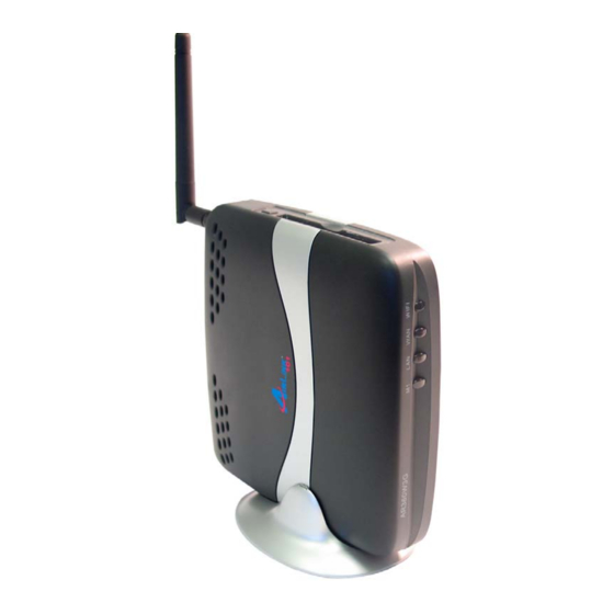
- Page 1 802.11g Wireless 3G Mobile Router Model # AR360W3G User’s Manual Ver. 1A...
-
Page 2: Table Of Contents
1. Introduction... 3 1.1 Functions and Features ... 3 2. Hardware Installation... 5 2.1 Connect the Router ... 5 2.2 Verify Connection to Router... 6 3. Configure the Router... 10 3.1 Setup Wizard... 10 4. Verify Connection Status and Wireless Settings ... 18 4.1 Checking the System Status... -
Page 3: Introduction
1. Introduction Congratulations on your purchase of this 802.11g Wireless 3G Router. This product is specifically designed for business travelers or SOHO needs. It provides an extended WAN solution, 3G Mobile PC Card for Internet surfing and is easy to configure and share the Internet even for non-technical users. - Page 4 • VPN Pass-Through o Support VPN pass-through. • SPI Mode Supported o When SPI Mode is enabled, the router will check every incoming packet to determine if the packet is valid. • DoS Attack Detection Supported o When this feature is enabled, the router will detect and log any DoS attack that comes from the Internet.
-
Page 5: Hardware Installation
2. Hardware Installation 2.1 Connect the Router Note: Prior to connecting the router, be sure to power off your computer and the router. Step 1 (Option1) Insert the 3G card into the card slot on the router facing up, (Option2) or, connect your DSL/Cable modem to the WAN port on the router. Step 2 Connect one end of an Ethernet cable to your computer’s network card and connect the other end to the LAN port on the router. -
Page 6: Verify Connection To Router
2.2 Verify Connection to Router Step 1 Go to Start, Run, type command (for Windows 95/98/ME) or cmd (for Windows 2000/XP) and click OK. For Windows Vista, click start and type in “command prompt” in the search box. Click on Command Prompt in the search results box. You will see the command prompt as below. - Page 7 Step 5 Type ipconfig/renew and press Enter. You should get an IP address of 192.168.1.x (where x is a number between 2 - 254). Proceed to Section 3, Configure the Router. If you don’t get an IP address, reset the router by holding in the reset button at the back of the router for 10 seconds while it is ON and try ipconfig/renew again.
- Page 8 Step 8 After your IP address is released, click Renew. You should get an IP address of 192.168.1.x (where x is a number between 2 - 254). If you don’t get an IP address, reset the router by holding in the reset button at the back of the router for 10 seconds while it is ON and try Renew again.
-
Page 10: Configure The Router
3. Configure the Router 3.1 Setup Wizard Step 1 Open the web browser and type 192.168.1.1 in the URL Address field and press Enter. Step 2 Enter admin for the password field and click Log in. Step 3 Click on Wizard from the main menu and click Next to begin the Setup Wizard. - Page 11 Step 4 You can change the password of the router here if you like. The default password is admin. Note: If you happen to forget your new password, you can reset the password back to admin by holding down the reset button on the back of the router for 10 seconds.
- Page 12 3G Mobile PC Card If you are going to use a 3G card, select 3G and click Next. Proceed to Step 5a. Cable Modem If you use cable modem, select Dynamic IP Address and click Next. Proceed to Step If you use DSL, select PPP over Ethernet and click Next. Proceed to Step 5c.
- Page 13 For 3G Mobile PC Card Users: Step 5a Enter the Phone number, Username, and Password given to you by your internet service provider into the appropriate boxes. Click Next when done and proceed Step...
- Page 14 Below are the examples for Cingular, Verizon, and Sprint: Cingular Phone Number: *99***1# Username: xxx@cingulargprs.com Password: xxxxx Verizon Phone Number: #777 Username: xxx@vzw3g.com Password: xxxxx Sprint Phone Number: #777 Username: xxx@sprintpcs.com Password: xxxxx If you are not sure about your account information, please contact your 3G Mobile service provider.
- Page 15 Step 5b If your ISP has provided you with a host name, enter it in the Host Name field. If your ISP requires a registered MAC Address, click on the Clone MAC button. Click Next when done and proceed to For DSL Users: Step 5c Fill in the applicable fields according to the information provided by your ISP.
- Page 16 Note: Depending on the ISP, you may need to include the domain name with your account name. Example: username@sbcglobal.net However, some DSL service providers may use Dynamic IP Address instead of PPP over Ethernet. You can contact your ISP to find out the correct WAN Type information. Step 6 If you wish to share access to your router wirelessly, click the radio button for On next to wireless radio and click Next.
- Page 17 Step 9 Click Apply Settings to save your settings and complete the configuration.
-
Page 18: Verify Connection Status And Wireless Settings
4. Verify Connection Status and Wireless Settings 4.1 Checking the System Status View the System Status to verify your Internet connection. Step 1 Login to the router’s web configuration page and click on the Status link from the Main Menu. Step 2 Verify that the WAN Status displays valid numbers (instead of all 0’s). - Page 19 If you use DSL and you see all 0’s, click on the Connect button. Step 3 Once you clicked the Renew or Connect button, you should see some numbers under WAN Status. This means you have successfully established Internet connection.
-
Page 20: Connecting To The Router Wirelessly
Note: If you still see all 0’s after clicking on the Renew or Connect button, try the troubleshooting tips at the end of this manual. 4.2 Connecting to the Router Wirelessly Below are the default wireless settings of the router. You must configure your wireless network adapter to the same settings in order to establish a wireless connection with the router. -
Page 21: Web Configuration
5. Web Configuration 5.1 Accessing the Web Configuration Utility You may configure the router through the web browser using the Web Configuration Utility. Step 1 Open the web browser and type in 192.168.1.1 and press Enter. Step 2 Enter admin for the password field and click Log in. You will see the Web Configuration Utility’s home page (System Status). -
Page 22: Basic Setting
5.2 Basic Setting 5.2.1 Primary Setup You can set the router’s LAN IP address and change the WAN type (Internet Connection Type) on this page. - Page 23 LAN IP Address: The router’s default IP address is 192.168.1.1. You can change this address to suit your existing network. WAN Type: Displays the current WAN type (Internet Connection Type) selected. Virtual Computers...
-
Page 24: Dhcp Server
The Virtual Computer function enables you to map the Global IP (WAN IP address) assigned by your ISP to the Local IP (LAN IP address) of your computer. This can only be used with Static IP and Dynamic IP WAN types. Global IP: Enter the global IP address (WAN IP) assigned by your ISP. - Page 25 DHCP Server: Select either to Enable or Disable the DHCP service (Default is Enable). IP Pool Starting Address: Enter the start of the IP pool range. IP Pool Ending Address: Enter the end of the IP pool range. Domain Name: Enter the domain name of your network (optional). Click on the More>>...
-
Page 26: Wireless
5.2.3 Wireless This page allows you to configure the router’s wireless security. By default the wireless encryption is disabled. It is recommended that you enable encryption for your wireless connection. Wireless: Enable or Disable the wireless function. WMM Capable: Wi-Fi Multimedia (WMM) provides basic Quality of service features by prioritizing traffic according to four Access Categories - voice, video, best effort, and background. -
Page 27: Forwarding Rules
Old Password: Enter the current login password. New Password: Enter the new login password. Reconfirm: Enter the new login password again. Click Save to save any changes or click Undo to cancel any changes. 5.3 Forwarding Rules 5.3.1 Virtual Server If you want to allow Internet users to access your internal web server or ftp server, you can use the Virtual Server function to open up the ports required to access your internal servers. -
Page 28: Special Ap
Service Ports: Enter the service port you wish to open to the Internet. Server IP: Enter the LAN IP address of the server you want the Internet users to access. Enable (check box): Check on this box to open the port. Use Rule# (optional): Enter the Schedule Rule # you wish to apply to the ID. -
Page 29: Dmz
Trigger: Enter the Outbound port number used by the application. Incoming Ports: Enter the Incoming port number used by the application. Enable (check box): Check this box to open the ports. Popular applications: Select from a list of popular applications. Copy to (button): Select the ID # (1 ~ 8) you want to paste the port numbers to first and then click on this button to paste the port numbers to the applicable fields. - Page 30 IP Address of DMZ Host: Enter the LAN IP address of the computer you wish to set as the DMZ host and check on the Enable box. Click Save to save any changes or click Undo to cancel any changes.
-
Page 31: Security Setting
5.4 Security Setting 5.4.1 Packet Filter Packet Filter enables you to control which packets are allowed to pass through the router. Outbound filter applies on all outbound packets. However, Inbound filter applies to packets that are destined to Virtual Servers or DMZ host only. Outbound Packet Filter is the default packet filter page. - Page 32 • Destination port address • Protocol: TCP or UDP or both. • Use Rule# For source or destination IP address, you can define a single IP address (192.168.1.100) or a range of IP addresses (192.168.1.100-192.168.1.254). An empty field implies all IP addresses. For source or destination port, you can define a single port (80) or a range of ports (1000-1999).
-
Page 33: Domain Filter
5.4.2 Domain Filter Domain Filter lets you prevent users from accessing any specified domain. Domain Filter: Check the Enable box to activate the Domain Filter function. Log DNS Query: Check the Enable box to log the action of someone trying to access the specified domain. -
Page 34: Url Blocking
5.4.3 URL Blocking URL Blocking will block the local computers from accessing pre-defined web sites. The main difference between Domain filter and URL Blocking is that Domain filter requires you to input a suffix like .com or .org, etc., while URL Blocking only requires you to input a keyword. -
Page 35: Mac Address Control
5.4.4 MAC Address Control MAC Address Control allows you to assign different access rights for different users and to assign a specific IP address to a certain MAC address. MAC Address Control: Check the Enable box to activate the MAC Address Control function. -
Page 36: Miscellaneous Items
Click Save to save any changes or click Undo to cancel any changes. 5.4.5 Miscellaneous Items Remote Administrator Host/Port: In general, only local users can browse the router’s built-in web configuration utility to perform administration tasks. Remote Administration enables you to perform administrative tasks from remote host. If this feature is enabled, only the host with the specified IP address can perform remote administration. - Page 37 Disable VPN pass through: You can disable VPN pass through here. Click Save to save any changes or click Undo to cancel any changes.
-
Page 38: Advanced Settings
5.5 Advanced Settings 5.5.1 System Time This page allows you to configure the system time of your router. Get Date and Time by NTP Protocol: Select this option if you want to obtain the time from a Network Time Server. Time Server: Select the time server you want to sync with. -
Page 39: System Log
Time: Manually set the Hour, Minute, and Second. Click Save to save any changes or click Undo to cancel any changes. 5.5.2 System Log This page allows you to export the system logs to specific destination by means of syslog (UDP) and SMTP (TCP). IP Address for Syslogd: Enter the destination IP Address where the syslogd will be sent. -
Page 40: Dynamic Dns
View Log (button): Displays the system log. Click Save to save any changes or click Undo to cancel any changes. 5.5.3 Dynamic DNS Dynamic DNS allows any user who wishes to access your server to reach it by a registered DNS name instead of an IP address. Before you enable Dynamic DNS, you need to register an account with one of the Dynamic DNS servers listed in the Provider field. -
Page 41: Snmp
Enter your Host Name, Username, and password for the DDNS account in the respective fields. Click Save to save any changes or click Undo to cancel any changes. 5.5.4 SNMP Enable SNMP: select to enable SNMP for local and/or remote segments. Get Community: Enter the desired community Set Community: Enter the desired community... -
Page 42: Routing
5.5.5 Routing The Routing Table allows you to set which network interface address to use for outgoing IP data grams. If you have more than one router and subnet, you will need to configure the routing table to direct the packets to follow the proper routing path so different subnets can communicate with each other. -
Page 43: Scheduling
5.5.6 Scheduling The Scheduling allows you to set the time when certain services will be on or off. Scheduling works in conjunction with Virtual Server and Packet Filter to determine when these services will be active or inactive. Schedule: Check the Enable box to activate the Schedule Rule function. Click on Add New Rule button to add a new schedule rule. - Page 44 Set the day and time that the rule applies to. In the above example, the rule is called ftp time, and it is set to be active everyday from 14:00 ~ 18:00 (2:00 pm ~ 6:00 pm). Click Save to save any changes or click Undo to cancel any changes. Once you have created the new rule, you can call up this rule from the Virtual Server and Packet Filter page and apply the schedule rule to any IDs in the Virtual Server or Packet Filter page.
-
Page 45: Toolbox
You can follow the same principle in applying the schedule rule to the packet filters. 5.6 Toolbox 5.6.1 System Info This page allows you to view the System Log and Routing Table. -
Page 46: Firmware Upgrade
5.6.2 Firmware Upgrade This page allows you to update the router’s firmware. 1. Download the latest firmware from www.airlink101.com web site. 2. Click the Browse button to locate the firmware. Be sure to unzip the file first. 3. Click on Upgrade. 4. -
Page 47: Backup Setting
5.6.3 Backup Setting Once you have configured all of the router’s settings, you can backup the settings as a file on your hard drive. (The file will be named config.bin). Click Backup Setting Save the configuration file to a location on your hard drive. To load a previously saved configuration file into the router, click on Restore Setting and select the file containing your settings. -
Page 48: Reset To Default
5.6.4 Reset to Default Click Reset to Default to reset all of the router’s settings to their original values. Click OK to restore all settings to factory default. -
Page 49: Reboot
5.6.5 Reboot Click Reboot to reboot the router. Click OK to reboot the router. -
Page 50: Miscellaneous
5.6.6 Miscellaneous Wake-on-LAN is a technology that enables you to power up a network device remotely. In order to use this feature, the target device must be Wake-on-LAN enabled and you have to know the MAC address of the device, i.e. 00-11-22-33-44-55. Clicking the Wake up button will make the router send a wake-up frame to the target device immediately. - Page 51 Step 3 Proceed through the rest of the setup. Step 4 Verify the Connection Status as described in Section 4. For DSL Users Only Step 1 Go to the router’s Setup Wizard. Step 2 At the PPPoE setting, double-check the spelling of your Account name and Password.
-
Page 52: Appendix - Specifications
Appendix – Specifications Standards • IEEE 802.11b , 802.11g • IEEE 802.3, 802.3u • IEEE 802.3x Flow Control support for Full-Duplex mode Frequency Range • 2.4 ~ 2.483GHz WAN Type • DHCP, PPPoE • 3G • Static • L2TP, PPTP Channel •... -
Page 53: Technical Support
Technical Support E-mail: support@airlink101.com Toll Free: 1-888-746-3238 Web Site: www.airlink101.com *Theoretical maximum wireless signal rate based on IEEE standard 802.11g specifications. Actual data throughput will vary. Network conditions and environmental factors, including volume of network traffic, building materials and construction, mix of wireless products used, radio frequency interference (e.g., cordless telephones and microwaves) as well as network overhead lower actual data throughput rate.