
Subscribe to Our Youtube Channel
Related Manuals for Midea MSC-09HRDN1-QD0(E)


Summary of Contents for Midea MSC-09HRDN1-QD0(E)
-
Page 1: Service Manual
SERVICE MANUAL MIDEA AIRCONDITIONER DC INVERTER SPLIT WALL-MOUNTED TYPE MSC-09HRDN1-QD0(E) MSC-12HRDN1-QC6(E) MSH-09HRDN1-QD0(E) MSH-12HRDN1-QC6(E) V1.2 Apr., 2007... -
Page 2: Table Of Contents
CONTENTS 1. Precaution ..............................1 1.1 Safety Precaution ..............................1 1.2 Warning ................................1 2. Function................................ 4 3. Dimension ..............................6 3.1 Indoor Unit................................6 MSC-09HRDN1-QD0(E) MSC-12HRDN1-QC6(E) ..................6 MSH-09HRDN1-QD0(E) MSH-12HRDN1-QC6(E) ..................6 3.2 Outdoor Unit ................................ 7 MOC-09HDN1-QD0(E) MOC-12HDN1-QC6(E) ................... 7 4. - Page 3 9.9 Forced operation function..........................31 9.10 Action of 4-way valve............................31 9.11 Two speeds outdoor fan function ........................31 9.12 Timer function..............................31 9.13 Sleep function mode............................31 9.14 Auto-Restart function............................32 9.15 Ionizer/Plasma dust collector function(optional) ....................32 9.16 Outdoor chassis heating cable (optional)......................32 10.
-
Page 4: Precaution
1. Precaution installation stand. 1.1 Safety Precaution It may cause injury, accident, or damage to the To prevent injury to the user or other people product. and property damage, the following instructions Be sure the installation area does not must be followed. deteriorate with age. - Page 5 It may cause corrosion on the product. Corrosion, arrives. particularly on the condenser and evaporator fins, There is risk of property damage, failure of product, could cause product malfunction or inefficient or electric shock. operation. Do not open the inlet grill of the product during operation.
- Page 6 your skin or clothes, wash it well with clean The chemical in batteries could cause burns or other health hazards water. Do not use the remote of the batteries have leaked.
-
Page 7: Function
2. Function Indoor unit Operation by remote controller Sensing by room temperature Room temperature sensor. Pipe temperature sensor. Room temperature control Maintain the room temperature in accordance w ith the setting temperature. Anti-freezing control in cooling Prevent the water being freezed on evaporator by sensing the evaporator pipe temperature in cooling mode Ionizer (Optional) Time Delay Safety control... - Page 8 Outdoor unit Power relay control The unit has 3 mins delay between continuously ON/OFF operations. Low noise air flow system Bird tail propeller fan makes the outdoor unit run more quietly. Hydrophilic aluminum fin The hydrophilic fin can improve the heating efficiency at operation mode. 4 way valve control It is only operated in the heating operation mode except defrosting operation.
-
Page 9: Dimension
3. Dimension 3.1 Indoor Unit MSC-09HRDN1-QD0(E) MSC-12HRDN1-QC6(E) MSH-09HRDN1-QD0(E) MSH-12HRDN1-QC6(E) -
Page 10: Outdoor Unit
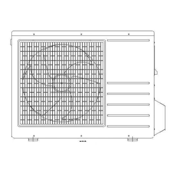
3.2 Outdoor Unit MOC-09HDN1-QD0(E) MOC-12HDN1-QC6(E) -
Page 11: Specification
4. Specification Indoor MSC-09HRDN1-QD0(E) MSC-12HRDN1-QC6(E) Outdoor MOC-09HDN1-QD0(E) MOC-12HDN1-QC6(E) Power supply Ph-V-Hz 1,220-240V~,50Hz 1, 220-240V~, 50Hz Capacity Btu/h 9000(3100~11200) 12000(3800~14700) Input 660(300~1100) 970(400~1480) Cooling Rated current 2.9(1.3~4.8) 4.3(1.8~6.5) Btu/w.h, w/w 13.6,4.0 12.4, 3.62 Capacity Btu/h 10000(3300~12300) 13000(4000~15200) Input 690(310~1150) 950(390~1460) Heating Rated current 3.0(1.4~5.0) 4.2(1.7~6.4) - Page 12 Indoor MSH-09HRDN1-QD0(E) MSH-12HRDN1-QC6(E) Outdoor MOC-09HDN1-QD0(E) MOC-12HDN1-QC6(E) Power supply Ph-V-Hz 1,220-240V~,50Hz 1, 220-240V~, 50Hz Capacity Btu/h 9000(3100~11200) 12000(3800~14700) Input 660(300~1100) 970(400~1480) Cooling Rated current 2.9(1.3~4.8) 4.3(1.8~6.5) Btu/w.h, w/w 13.6,4.0 12.4, 3.62 Capacity Btu/h 10000(3300~12300) 13000(4000~15200) Input 690(310~1150) 950(390~1460) Heating Rated current 3.0(1.4~5.0) 4.2(1.7~6.4) Moisture Removal...
-
Page 13: Refrigerant Cycle Diagram
5. Refrigerant cycle diagram... -
Page 14: Wiring Diagram
6. Wiring diagram 6.1 Indoor Unit MSC-09HRDN1-QD0(E) MSC-12HRDN1-QC6(E) MSH-09HRDN1-QD0(E) MSH-12HRDN1-QC6(E) -
Page 15: Outdoor Unit
6.2 Outdoor Unit MOC-09HDN1-QD0(E) MOC-12HDN1-QC6(E) -
Page 16: Installation Details
7. Installation details 7.1 Wrench torque sheet for installation Outside diameter Torque inch Kgf.m Ф6.35 Ф9.52 Ф12.7 Ф15.88 7.2 Connecting the cables The power cord of connect should be selected according to the following specifications sheet. Grade Unit 7.3 Pipe length and the elevation Standard Max. -
Page 17: Air Purging Of The Piping And Indoor Unit
7.4 Air purging of the piping and indoor unit Required tools: Hexagonal wrench; adjustable wrench; torque wrenches, wrench to hold the joints and gas leak detector. Note: The air in the indoor unit and in the piping must be purged. If air remains in the refrigeration piping, it will affect the compressor, reduce the cooling capacity, and could lead to a malfunction of unit. -
Page 18: Pumping Down (Re-Installation)
7.5 Pumping down (Re-installation) Procedure 1. Confirm that both the 2-way and 3-way valves are set to the opened position. Remove the valve stem caps and confirm that the valve stems are in the opened position. Be sure to use a hexagonal wrench to operate the valve stems. 2. -
Page 19: Re-Air Purging (Re-Installation)
7.6 Re-air purging (Re-installation) Procedure: 1. Confirm that both the 2-way and 3-way valves are set to the closed position. 2. Connect the charge set and a charging cylinder to the service port of the 3-way valve. Leave the valve on the charging cylinder closed. 3. -
Page 20: Balance Refrigerant Of The 2-Way, 3-Way Valves
7.7 Balance refrigerant of the 2-way, 3-way valves Procedure: 1. Confirm that both the 2-way and 3-way valves are set to the open position. 2. Connect the charge set to the 3-way valve’s service port. Leave the valve on the charge set closed. Connect the charge hose with the push pin to the service port. -
Page 21: Evacuation
7.8 Evacuation Procedure: 1. Connect the vacuum pump to the charge set’s centre hose. 2. Evacuation for approximately one hour. Confirm that the gauge needle has moved toward -0.1 Mpa (-76 cmHg) [vacuum of 4 mmHg or less]. 3. Close the valve (Low side) on the charge set, turn off the vacuum pump, and confirm that the gauge needle does not move (approximately 5 minutes after turning off the vacuum pump). -
Page 22: Gas Charging
7.9 Gas charging Procedure: 1. Connect the charge hose to the charging cylinder. Connect the charge hose which you disconnected from the vacuum pump to the valve at the bottom of the cylinder. 2. Purge the air from the charge hose. Open the valve at the bottom of the cylinder and press the check valve on the charge set to purge the air (be careful of the liquid refrigerant). -
Page 23: Operation Characteristics
8. Operation characteristics 8.1 MSC-09HRDN1-QD0(E) Piping Length Characteristics(Cooling) Cooling Characteristics 2.58 2.74 2.54 2.68 2.50 2.62 2.46 2.56 2.42 2.50 2.38 2.44 2.34 2.38 2.30 2.32 0.660 0.72 0.655 0.70 0.650 0.68 0.645 0.66 0.640 0.64 0.635 0.62 0.60 0.630 10 11 12 13 14 25 27 29 31 33 35 37 39 41 43... -
Page 24: Msc-12Hrdn1-Qc6(E)
8.2 MSC-12HRDN1-QC6(E) Piping Length Characteristics(Cooling) Cooling Characteristics 3.50 3.44 3.38 3.32 3.26 3.20 3.14 3.08 0.97 1.08 0.96 1.04 0.95 1.00 0.94 0.96 0.93 0.92 0.92 0.88 0.84 0.91 10 11 12 13 14 25 27 29 31 33 35 37 39 41 43 ℃... -
Page 25: Msh-09Hrdn1-Qd0(E)
8.3 MSH-09HRDN1-QD0(E) Piping Length Characteristics(Cooling) Cooling Characteristics 2.58 2.74 2.54 2.68 2.50 2.62 2.46 2.56 2.42 2.50 2.38 2.44 2.34 2.38 2.30 2.32 0.660 0.72 0.655 0.70 0.650 0.68 0.645 0.66 0.640 0.64 0.635 0.62 0.60 0.630 10 11 12 13 14 25 27 29 31 33 35 37 39 41 43 ℃... -
Page 26: Msh-12Hrdn1-Qc6(E)
8.4 MSH-12HRDN1-QC6(E) Piping Length Characteristics(Cooling) Cooling Characteristics 3.50 3.44 3.38 3.32 3.26 3.20 3.14 3.08 0.97 1.08 0.96 1.04 0.95 1.00 0.94 0.96 0.93 0.92 0.92 0.88 0.84 0.91 10 11 12 13 14 25 27 29 31 33 35 37 39 41 43 ℃... -
Page 27: Electronic Function
9. Electronic function 9.1 Abbreviation T1: Indoor ambient temperature T2: Pipe temperature of indoor heat exchanger T3: Pipe temperature of outdoor heat exchanger T4: Outdoor ambient temperature 9.2 Display function 9.2.1 Icon explanation on indoor display board. MSC-09HRDN1-QD0(E) MSC-12HRDN1-QC6(E) MSH-09HRDN1-QD0(E) MSH-12HRDN1-QC6(E) ①... -
Page 28: Protection
9.2.2 LED display control function. Pressing “LED display” button on remote controller will turn off all displays on indoor unit, while pressing once again, all displays will resume. 9.2.3 Display function in outdoor unit. 9.3 Protection 9.3.1 Three Minutes Delay at restart for compressor. 9.3.2 Temperature protection of compressor top. -
Page 29: Cooling Mode
9.4.3 The action of auto fan in fan-only mode is the same as auto fan in cooling mode with 24℃ setting temperature. ℃ high medium 9.5 Cooling Mode 9.5.1 The After start the operation frequency of compressor submits to following rule. -0.5 -1.0 When the machine is running and ∆T(=room temp. -
Page 30: Drying Mode
controller 6 times or more within 10 seconds(make sure indoor unit receives these signals), the machine will turn into rating capacity test mode, the buzzer will make a “di” sound for 2 seconds continuously. Also, indoor fan will change to rating speed, the frequency of compressor will be fixed as rating value. Any condition of above is not satisfied, the machine can not be turned into rating capacity test mode. - Page 31 ℃ setting fan speed low fan breeze super breeze fan stop If the compressor stops caused by room temperature rising, indoor fan will be forced to run 127 seconds with breeze. During this period, anti-cold-wind is disabled. After this, anti-cold –wind function is available. If the machine runs in rating capacity test mode, indoor fan runs with rating speed, and anti-cold-wind is disabled.
- Page 32 ∆Tcon(℃) 9.7.4 Outdoor unit current control in heating mode. comp. pause I3HEAT freq. descends if curr. rises; I2HEAT freq. remains if curr. descends I1HEAT running normally Remark: I1HEAT I2 HEAT I3 HEAT 9K Model 5.2 A 6.4 A 7.5 A 12K Model 5.2 A 6.4 A...
-
Page 33: Auto Mode Function
9.7.7 Defrosting action. compressor 4-way valve outdoor fan indoor fan indoor fan breeze 10s no longer than 10 minutes 9.7.8 Rating capacity test function. Set the indoor unit with remote controller as: high fan, 30℃ in heating mode, then press “TURBO” button on controller 6 times or more within 10 seconds(make sure indoor unit receives these signals), the machine will turn into rating capacity test mode, the buzzer will make a “di”... -
Page 34: Forced Operation Function
9.9 Forced operation function 9.9.1 Forced cooling and auto function can carry out with a touch button. In these two modes, the machine can be changed by remote controller to any other mode at any moment. 9.9.2 When the machine is off, pressing the touch button will carry the machine to forced auto mode, after this, if pressing the button once again within 5 seconds, the machine will turn into forced cooling mode. -
Page 35: Auto-Restart Function
9.13.3 Operation process in sleep mode is as follow: 1) After pressing ECONOMIC or SLEEP button on controller, the machine will turn into sleep mode. 2) When cooling, the setting temperature rises 1℃(be lower than 30℃) every one hour, 2 hour later the rising stops and indoor fan is fixed as low speed. -
Page 36: Troubleshooting
10. Troubleshooting Safety Because of there are capacitors in PCB and relative circuit in outdoor unit, even shut down the power supply, electricity power still are kept in capacitors, do not forget to discharge the electricity power in capacitor. Electrolytic Capacitors (HIGH VOLTAGE! CAUTION!) Bulb (25-40W) -
Page 37: Indoor Unit Error Display
10.1 Indoor Unit Error Display Display LED STATUS EEPROM parameter error Indoor / outdoor units communication protection Zero-crossing signal error Fan speed out of control Open or short circuit of outdoor temperature sensor Open or short circuit of room or evaporator temperature sensor IGBT over-strong current protection Over voltage or too low voltage protection Temperature protection of compressor top. - Page 38 LED6 LED5 LED4 LED1...
-
Page 39: Diagnosis And Solution
10.3 Diagnosis and Solution 10.3.1 E0(EEPROM parameter error) error diagnosis and solution Circuit or software error on indoor PCB Replace indoor PCB 10.3.2 E1(indoor / outdoor units communication protection) error diagnosis and solution Disconnect the power supply, after 1 minute, connect the power supply, turn on the unit with remote controller Does the unit work normally? - Page 40 10.3.4 E3(indoor fan speed out of control) diagnosis and solution Is the indoor fan motor Repair the connector and connector and connection reconnect good? Is voltage being applied to the fan motor? Indoor PCB is defective. (rang 90v-160v between Replace the indoor PCB. mid pin and N on CN1 Replace the indoor fan motor...
- Page 41 10.3.8 P1(over voltage or too low voltage protection) diagnosis and solution. Be sure the power supply is Is the power supply good? normal when using the units Replace the outdoor e-box. 10.3.9 P2(temperature protection of compressor top) diagnosis and solution. Is the connection Does compressor Reconnect and retest.
-
Page 42: Key Parts Checking
10.4 Key parts checking. 10.4.1. Compressor checking (Model: DA108X1C-20FZ3). Measure the resistance value of each winding by using the multi-meter. Position Resistance Value Blue - Red 0.71 Blue - Black (20℃) Red - Blue 10.4.2 Outdoor Fan Motor (Model: YDK24-6G). Measure the resistance value of each winding by using the multi-meter. - Page 43 10.4.5 Temperature Sensors. Room temp.(T1) sensor, Indoor coil temp.(T2) sensor, Outdoor coil temp.(T3) sensor, Outdoor ambient temp.(T4) sensor, Compressor exhaust temp.(Te) sensor. Measure the resistance value of each winding by using the multi-meter. Some frequently-used R-T data for T1,T2,T3 and T4 sensor: ℃...
- Page 44 UPDATE EXPLANATION: : : : V1.1 , Jan., 2007 Revised by Alex Jiang & Jim Xu 1. Correct some spelling and editing mistake. 2. Add the passage 9.14-9.16. 3. Add the passage 10.2 (Outdoor Unit Error Display). V1.2 , Apr., 2007 Revised by Alex Jiang 1.
Need help?
Do you have a question about the MSC-09HRDN1-QD0(E) and is the answer not in the manual?
Questions and answers