
Related Manuals for Aiphone AX-248C


Summary of Contents for Aiphone AX-248C
- Page 1 1205 A AX SERIES Integrated Security &Communication System AX-248C INSTALLATION &OPERATION MANUAL - 1 -...
-
Page 2: General Precautions
5. On products with ground terminals, connect to an earth ground. Fire or malfunction could result. 6. For DC powered systems, use Aiphone power supply model specified with system. If non-specified product is used, fire or malfunction could result. 7. Do not put anything on or cover the unit with cloth, etc. Fire or unit trouble could result. -
Page 3: Table Of Contents
SYSTEM CONFIGURATIONS System Configurations Capacity External integration example, Door station Master station, Central exchange unit PACKAGE CONTENTS Package contents (Mullion door station), (Vandal-resistant door station) Package contents (Master station), (16 call add-on selector), (Central exchange unit) INSTALLATION Installation location (Master station), (Door station), Visible range Cable, Wiring distance MOUNTING Mounting (Mullion door station) -
Page 4: System Configurations
SYSTEM CONFIGURATIONS Max. 8 Max. 120 Max. 24 Max. 32 Max. 32 Max. 32 AX-084C AX-248C CAT5e AX-320C CAT5e AX-320C CAT5e AX-320C - 4 - Max. 4 DC 24 V DC 24 V Max. 8 DC 24 V DC 24 V... -
Page 5: Capacity
• CO line adaptor • Video output [6] Power supply x2 Capacity • Door station: Maximum 120 stations (When AX-248C x1, AX-320C x3 used) • Master station: Maximum 4 stations (when AX-084C used) Maximum 8 stations (when AX-248C used) • Power supply:... - Page 6 AX-084C AX-248C External integration example [1] CCTV system [2] Access control system [3] AC transformer PT1210N (AC 12V, 10VA, for North America only) [4] Electric door strike EL-9S a. System log (RS-232C) b. Camera switching c Video signal d. Remote door release signal (RS-232C) e.
- Page 7 [1] AX-084C Standard central exchange unit • A maximum of 4 master stations and 8 door stations can be connected. [2] AX-248C Expanded central exchange unit • A maximum of 8 master stations and 24 door stations can be connected.
-
Page 8: Package Contents
PACKAGE CONTENTS Package contents (Mullion door station) [1] AX-DM mullion audio door station [2] Mounting screws [3] Operation manual Package contents (Vandal-resistant door station) [1] Vandal-resistant door station AX-DV, AX-DVF, AX-DV-P, AX- DVF-P [2] Special screwdriver [3] Directory card [4] Mounting screws and Anchor bolts (AX-DV, AX-DV-P) [5] Mounting screws (AX-DVF, AX-DVF-P) [6] Back box (AX-DVF,AX-DVF-P) ∗... - Page 9 [4] Connector cable [5] Screws for connecting master and add-on selector Package contents (Central exchange unit) [1] AX-084C, AX-248C, or AX-320C exchange unit [2] Mounting screws [3] Rack and wall mounting brackets x2 [4] Installation CD (AX-084C, AX-248C), including set-up software program and instruction manual.
-
Page 10: Installation
INSTALLATION Installation location (Master station) Install the video master station in a place where the screen is not exposed to direct sunlight. Installation location (Door station) Do not install a video door station in any of the following locations where lighting or the ambient environment could impact the display on the video master station due to the characteristics of the door station's camera. - Page 11 AX-DV AX-DV-P AX-DVF AX-DVF-P AX-DM IF-DA IE-JA IE-SS CAT5e AX-084C AX-248C AX-248C AX-320C AX-320C Pin 1 RJ-45 Plug PS-2420UL AX-084C PS-2420S AX-248C PS-2420DIN AX-248C Cable 1. CAT5e (24AWG) straight-thru EIA/TIA 568B 1 White-orange 2 Orange 3 White-green 4 Blue 5 White-blue...
-
Page 12: Mounting
MOUNTING AX-DM Mounting (Mullion door station) 1. Connect the CAT5e cable to the rear of the AX-DM. Use wires #3 (white-green) and #6 (green) as one conductor, and #7 (white-brown) and #8 (brown) as the other conductor (RJ-45 jack not used at Mullion door station). The other pairs are not used. -
Page 13: Mounting (Vandal-Resistant Door Station)
AX-DV AX-DV-P 77 mm 3" AX-DVF AX-DVF-P 27.5 mm 1-3/32" Mounting (Vandal-resistant door station) 1. Open the rear cover of the surface mount door station and insert the CAT5e cable (RJ45 plug). For the AX-DV-P, pass it through either the top or bottom cable inlet hole. For the AX-DV, pass it through the top cable inlet hole. - Page 14 AX-DV 100 mm 4" 77 mm 3" 8.5mm 1.3 mm 5/16" 1/16" AX-DV-P 100 mm 4" 77 mm 3" 8.5 mm 1.3 mm 5/16" 1/16" Ø16 mm 5/8" AX-DVF 146 mm 5-3/4" 104 mm 4-1/8" 114 mm 16 mm 4-1/2" 5/8"...
-
Page 15: Door Station Installation Dimensions
Door station installation dimensions [1] Center position of camera [2] Wiring holes Ø 16 mm 5/8" - 15 -... - Page 16 AX-16SW AX-8M AX-8MV 149 mm 5-7/8" 83.5 mm 65 mm 3-5/16" 2-9/16" 46 mm 1-13/16" - 16 - AX-8M AX-8MV...
-
Page 17: Mounting (Master Station)
[6] Optional connector [7] Mounting bracket When connecting the optional connector for a desktop installation, secure the connector wires with the tie wrap so that the wires do not come loose. AX-084C AX-248C AX-320C DO OR RE LEA SE RE DO OR... -
Page 18: Wiring
WIRING AX-DV AX-DV-P AX-DVF AX-DVF-P AX-DM [14] CAT5e IF-DA IE-JA RJ45 CAT5e AX-084C AX-248C AX-320C AX-320C Max. 3 AX-320C RJ45 [10] CAT5e [13] EL-9S CAT5e CAT5e CAT5e CAT5e CAT5e CAT5e CAT5e CAT5e - 18 - AX-8MV Max. 7 AX-16SW AX-8M... - Page 19 Wiring Securely insert wires into each terminal as shown. [1] AX-248C or AX-084C central exchange unit [2] AX-8MV video master station or AX-8M master station AX-16SW 16 call add-on selector [3] Video or audio-only door station [4] AX-320C add-on exchange unit...
-
Page 20: Names
NAMES AX-DV AX-DV-P AX-DM Names (Door station) [1] CALL button [2] Speaker [3] Microphone [4] Camera AX-DVF [5] Directory card [6] Proximity card reader [7] White LED AX-DVF-P - 20 -... -
Page 21: Names (Master Station)
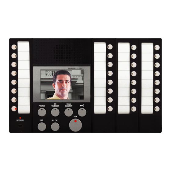
AX-8M / 8MV [20] [11] [21] [10] [18] [19] [9] [8] [7] [12] [27] [22] [22] [26] [28] [13] [23] [24] AX-16SW [28] Names (Master station) [1] Individual door station selector button (w/LED) [2] Individual master station selector button (w/LED) [3] Door release button (w/LED) [4] Scan monitor button (w/LED) [5] CO transfer button (w/LED) - Page 22 AX-084C AX-248C AX-320C - 22 - [10] [10] [11] [12] [12] [10] [12]...
-
Page 23: Names (Central Exchange Unit)
Names (Central exchange unit) [1] POWER switch [2] Door station port [3] Master station port [4] Add-on exchange unit port [5] CO line port [6] Setting/log port [7] Video output port [8] Video output trigger port [9] Door release relay port (L1 corresponds to door station D1, L2 to door station D2, etc.) [10] Power supply port [11] Add-on unit ID setting switch... -
Page 24: Setting Up
SETTING UP RS-232C AX-248C [10] [11] - 24 -... -
Page 25: Setup Tool
Setup tool ∗ Install the setup tool program on your PC (Windows ®) beforehand. • The setup software is on the CD that comes with the central exchange unit. • For installation (auto open), see startup.html. • A folder containing the setup tool is created on the desktop. 1. -
Page 26: Starting The Setup
New setting file Normal start-up Default setting file AX setup tool (default.cfg) Save Save as default Open Any setup file (xxxxxx.cfg) Save, Save as Starting the setup 1. Setup file and file operation • When the setup tool is started, the default data is read in and displayed. - Page 27 Central exchange unit setting 1. For the device used as "No.1", select "AX-084C" or "AX- 248C". 2. "COM Port" selects the serial communications port of the PC connected to central exchange unit 1. 3. Select the add-on exchange unit to be connected from among "No.2"...
- Page 28 - 28 -...
-
Page 29: Door Station Setting
Door station setting ∗ There are three methods for setting door stations: individual input, line copy-and-paste input, and column batch input. 1. Individual input [1] Central exchange unit number (cannot be input) • Displays the number of the central exchange unit to which the corresponding door station is connected. -
Page 30: Time Out Setting
1, 2, 3, 4, 5, 6, 7, 8, 9, 10 Time out setting 1. "Call from Door St. (Normal)" time setting [1] The time setting is "10-600 Seconds" or "Infinite". To change the calling time, click "(10-600 Seconds)". [2] If you click the box displaying the number of seconds for calls, you can edit it and the spin button is displayed. - Page 31 CO Transfer 1. To allow transfer of a door station call to a CO line, click "Enable". Do disallow, click "Disable". 2. If CO Transfer is activated, select the CO line detection method. To detect the CO line through reverse polarity, select "Detect". If not, select "Do Not Detect".
- Page 32 7-10 Normal start-up Default setting file (default.cfg) Save Save as default Open Any setup file (xxxxxx.cfg) Save, Save as New setting file Setup upload AX setup tool AX control unit 1 Setup download - 32 -...
-
Page 33: Uploading Settings And Save
7-10 Uploading settings and save 1. Setup data flow 2. Setup download menu When you select "CEU (C)" from "Tool (T)" menu and select "Download (D)", the setup data stored in the CEU is downloaded to the PC. Before starts downloading, password input is required. - Page 34 7-12 - 34 -...
-
Page 35: System Monitor
7-12 System monitor 1. System monitor start • When you select "Start System Monitoring (M)" from "Tool (T)", the system monitor is started. The display switches from the setup edit screen to the system monitor screen. 2. System monitor screen operation On the system monitor screen, "Scan Monitor", "Door Station button", "Off", and "Door Release"... - Page 36 7-14 7-15 Exiting the setup tool When you select "Exit (X)" from "File (F)", the setup tool closes. Help The version information dialog is displayed. - 36 -...
-
Page 37: Operations
OPERATIONS Calling a master station from door station and communicating There are two priority levels for calls from door stations, "Normal"and "Priority". 1. Press the door station CALL button. 2. The calling tone rings on the master station (for a normal call, an intermittent tremolo sound;... - Page 38 Calling a master station from a master station and communicating 1. Press individual selector button of master station. 2. The pre-tone (Pi-Po-n) sounds both master stations, and starts hands-free communication. The Talk LED lights when you talk and goes off as you listen to the caller. 3.
-
Page 39: All Call (Priority) (Master Station Paging), Monitor
CO line call from door station and communicating 1. If the CALL button is pressed at a door station while CO Transfer feature is set (with CO Transfer button lit), the call tone rings on the master station (for a normal call, an intermittent tremolo sound;... - Page 40 All call (priority) (master station paging) 1. When you press the ALL CALL button on the master station, all the individual master station selector button LEDs flash slowly. 2. If you press the ALL CALL button again, the flashing speeds up again.
- Page 41 Scan monitor 1. When the scan monitor button is pressed, the setting door stations can be monitored sequentially each set time interval. • Normally, monitoring is in order from the target door station with the lowest number. • If you press the scan monitor button while individually monitoring a target door station, monitoring starts with next to that door station.
-
Page 42: List Of Function Button Operations For Each Own Master Station Mode
8-11 List of function button operations for each own master station mode • Each operation is carried out when the audio channel is empty. • Even when a sub-station call only uses the video channel, the audio channel is also treated as filled. (The audio and video channels form a pair.) Current status Privacy... -
Page 43: Technical Precautions
(Two Power supply required per video system) • Current consumption: AX-084C: Video (Max.) 620 mA, Audio (Max.) 650 mA AX-248C: Video (Max.) 1100 mA, Audio (Max.) 1250 mA AX-320C: Video (Max.) 200 mA, Audio (Max.) 180 mA • Communication: <Auto> VOX <Manual>... - Page 44 This warranty shall not apply to any Aiphone product which has been subject to misuse, neglect, accident, or to use in violation of instructions furnished, nor extended to units which have been repaired or altered outside of the factory.