Graco Fire-Ball 425 Instructions-Parts List Manual
Hide thumbs
Also See for Fire-Ball 425:
- Instructions-parts list manual (20 pages) ,
- Installation and operations (34 pages) ,
- Instructions and parts list (24 pages)
Table of Contents
Advertisement
Instructions – Parts List
Parts
10:1 Fire–Ball
For pumping petroleum–based lubricating fluids only.
180 psi (12.4 bar) Maximum Incoming Air Pressure
1800 psi (124 bar) Maximum Fluid Working Pressure
Model 205626, Series J
Universal Pump
Model 222065, Series B
55-Gallon Drum Cover-Mount Pump
Model 222095, Series B
55-Gallon Drum Bung-Mount Pump
Important Safety Instructions.
Read all warnings and instructions in this manual.
Save these instructions.
Mascott Equipment Co
Portland
GRACO INC. P.O. BOX 1441 MINNEAPOLIS, MN 55440-1441
(800) 452-5019
(800) 481-7311
Copyright 1996, Graco Inc. is registered to I.S. EN ISO 9001
r
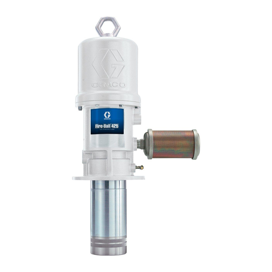
Model 205626 shown
Seattle
Pasco
(888) 450-7867
425 Pump
308655H
TI1071
Advertisement
Table of Contents

Related Manuals for Graco Fire-Ball 425


Summary of Contents for Graco Fire-Ball 425
- Page 1 Read all warnings and instructions in this manual. Save these instructions. Model 205626 shown TI1071 Mascott Equipment Co Portland Seattle Pasco GRACO INC. P.O. BOX 1441 MINNEAPOLIS, MN 55440-1441 (800) 452-5019 (800) 481-7311 (888) 450-7867 Copyright 1996, Graco Inc. is registered to I.S. EN ISO 9001...
-
Page 2: Table Of Contents
D This equipment is for professional use only. D Read all instruction manuals, tags, and labels before you operate this equipment. D Use the equipment only for its intended purpose. If you are not sure, call your Graco distributor. D Do not alter or modify this equipment. - Page 3 WARNING WARNING INJECTION HAZARD Fluid from the dispensing valve, leaks, or ruptured components can inject fluid into your body and cause extremely serious injury, including the need for amputation. Fluid splashed in the eyes or on the skin can also cause serious injury. D Fluid injected into the skin may look like just a cut, but it is a serious injury.
-
Page 4: Installation
The typical installation shown in Fig.1 is only a guide to CAUTION help you select and install a pump; it is not an actual system design. Contact your Graco distributor for Always mount the pump firmly to a bracket or a assistance in designing a system to suit your needs. - Page 5 Installation D Install an air line filter (B) to remove harmful dirt System Accessories and contaminants from your compressed air supply. CAUTION D Install a bleed-type master air valve (A) to isolate the accessories for servicing. See Fig. 1. To order Do not hang the air accessories directly on the air a bleed-type master air valve, order Part No.
- Page 6 Installation Grounding To ground the pump, remove the ground screw (Z) and insert through the eye of the ring terminal at end of Proper grounding is an essential part of maintaining a the ground wire (Y). Fasten the ground screw back onto safe system.
-
Page 7: Operation
Operation Pressure Relief Procedure WARNING WARNING HAZARDOUS VAPORS The air motor exhaust coming out of the INJECTION HAZARD muffler could contain harmful materials, To reduce the risk of serious bodily such as oil, antifreeze, or some of the injury, including fluid injection or material being pumped. -
Page 8: Troubleshooting
Operation 8. If the pump will be unattended for any period of CAUTION time, if there is an air supply interruption, or to shut off the system at the end of the work shift, always Never allow the pump to run dry of the fluid being relieve the pressure. -
Page 9: Air Motor And Throat Service
Air Motor and Throat Service Before You Start CAUTION D Be sure you have all necessary parts on hand. Do not damage the plated surface of the trip rod Repair Kit 238751 includes repair parts for the air (31). Damaging the surface of the trip rod can motor and pump. - Page 10 Air Motor and Throat Service 10. Pull the piston assembly (27) from the air motor 15. In this step, while you are prying with the screw- base (28), and set it aside. driver with one hand, cover the toggle assemblies with your other hand so as to catch the spring- loaded toggle assemblies when they snap out of the lugs.
- Page 11 Air Motor and Throat Service Cut off tops of poppets as indicated by dotted lines. Turn lock- wires 0.125” (3.18 mm) 04422 05612 Cutaway View Fig. 4 Reassembly 1. Place the piston rod (29) flats in the vise with the 7.
- Page 12 Air Motor and Throat Service 12. Grease and reinstall the seal (2*) with the lips 18. Clean the threads of the piston/valve seat (109), down, thread the throat bearing (36) into the air Apply Loctiter to the threads, and thread the motor base (28), and torque the throat bearing to assembly from Step 16 onto the displacement 30 to 40 ft-lb (41 to 54 N.m) using a 1 5/8-in.
-
Page 13: Displacement Pump Service
Displacement Pump Service Disassembly Displacement Pump. See Fig 6. NOTE: Clean and inspect all parts for wear or damage NOTE: Be sure you have all necessary parts on hand. as you disassemble them. Replace parts as Repair Kit 238751 includes repair parts for the needed. -
Page 14: Parts List
Parts List Model 205626, Series J Model 222065, Series B Model 222095, Series B Wall-Mount Universal Pump 55-Gallon Drum Cover-Mount Pump 55-Gallon Drum Bung-Mount Pump Includes items 1 to 113 Includes items 1 to 113, 150, and 151 Includes items 1 to 113, 150,152, and 153 Part No. -
Page 15: Parts Drawing
Parts Drawing Torque to 30 to 40 ft-lb (41 to 54 N.m) Torque to 45 to 55 ft-lb (61 to 75 N.m) Lips face down Lips face up When assembling the fluid cylinder (110) over the assembled fluid piston (107, 109, 113), use the piston assembly tool included in repair kit 238751 and steps 21 through 23 on page 12 . -
Page 16: Dimensions
Dimensions Mounting Hole Layout MODEL 205626, Series J 2.25-in. (57.2 mm) diameter clearance hole 1/2-in. npt air inlet Four 0.406-in. (10.3 mm) holes on 7-in. (177.8 mm) bolt 18.4 in. circle (467 mm) 3/4-in. npt fluid Four threaded outlet Model holes on bottom of 205626 air motor base are... -
Page 17: Performance Chart
Performance Chart black curves=fluid outlet pressure gray curves=air consumption 1400 (96.6) A 40 psi (2.8 bar) air pressure B 70 psi (4.8 bar) air pressure 1300 C 100 psi (6.9 bar) air pressure (89.7) D 150 psi (10.4 bar) air pressure 1200 (82.8) 1100... -
Page 18: Warranty
With the exception of any special, extended, or limited warranty published by Graco, Graco will, for a period of twelve months from the date of sale, repair or replace any part of the equipment determined by Graco to be defective.