Graco 205626 Instructions-Parts List Manual
Hide thumbs
Also See for 205626:
- Instructions-parts list manual (18 pages) ,
- Quick start manual (50 pages) ,
- Installation and operations (34 pages)
Table of Contents
Advertisement
Quick Links
Instructions - Parts List
10:1 Fire-Ball
For pumping non-corrosive and non-abrasive oils and lubricants only. For professional use
only.
Model 205626, Series K
Universal Pump
Model 222065, Series C
55-Gallon Drum Cover-Mount Pump
Model 222095, Series C
55-Gallon Drum Bung-Mount Pump
1800 psi (12.4 MPa, 124.1 bar) Maximum Working Pressure
180 psi (1.24 MPa, 12.4 bar) Maximum Air Input Pressure
Important Safety Instructions
Read all warnings and instructions in this
manual before using the equipment.
Save these instructions.
Related Manuals
Manual in
Description
English
308201
Pump Runaway Valve
®
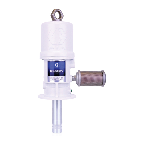
425 Pump
Model 205626 shown
308655K
EN
Advertisement
Table of Contents

Related Manuals for Graco 205626


Summary of Contents for Graco 205626
-
Page 1: Related Manuals
10:1 Fire-Ball 425 Pump 308655K For pumping non-corrosive and non-abrasive oils and lubricants only. For professional use only. Model 205626, Series K Universal Pump Model 222065, Series C 55-Gallon Drum Cover-Mount Pump Model 222095, Series C 55-Gallon Drum Bung-Mount Pump 1800 psi (12.4 MPa, 124.1 bar) Maximum Working Pressure... -
Page 2: Table Of Contents
California Proposition 65 ....21 Graco Standard Warranty ....22... -
Page 3: Warnings
Warnings Warnings The following warnings are for the setup, use, grounding, maintenance, and repair of this equipment. The exclamation point symbol alerts you to a general warning and the hazard symbols refer to procedure-specific risks. When these symbols appear in the body of this manual or on warning labels, refer back to these Warnings. Product-specific hazard symbols and warnings not covered in this section may appear throughout the body of this manual where applicable. - Page 4 Warnings WARNING TOXIC FLUID OR FUMES HAZARD Toxic fluids or fumes can cause serious injury or death if splashed in the eyes or on skin, inhaled, or swallowed. • Read Safety Data Sheets (SDSs) to know the specific hazards of the fluids you are using. •...
-
Page 5: Typical Installation
The typical installation shown in F . 1 is only a guide for selection and installation of a pump. It is not an actual system design. Contact your Graco representative or Graco distributor for assistance in the design of a suitable system. -
Page 6: Installation
Installation Installation System Accessories • Insert the muffler (5) into the 3/4 npt muffler port and tighten using a wrench on the flats of the muffler near the male threads. NOTICE • Install an air line lubricator (N) for automatic air motor lubrication. -
Page 7: Grounding
The pump shown in F . 1 is a wall mounted universal clamp, order Part No. 222011. pump, Model 205626. To oder the wall mounting bracket, order Part No. 238425. Bung Mount Pump model 222095 is designed for bung mounting on a 55-gallon drum. -
Page 8: Operation
Operation Operation Start Up and Adjustment Pressure Relief Procedure Follow the Pressure Relief Procedure whenever you see this symbol. The maximum working pressure of each component in the system may not be the same. To reduce the risk of over-pressurizing any component in the system, be sure you know the maximum working pressure of each component. -
Page 9: Recycling And Disposal
Operation Recycling and Disposal 2. Open the dispensing valve (J) into a grounded metal waste container, making firm metal-to-metal contact between the container and valve. End of Product Life 3. Open the pump air regulator (C) slowly, just until the pump is running. -
Page 10: Troubleshooting
Troubleshooting Troubleshooting Follow Pressure Relief Procedure, page 8, before checking or repairing the pump. Check all possible problems and causes before disassembling pump. Problem Cause Solution Pump fails to operate, or there is no Inadequate air supply pressure or Increase air supply; clear fluid flow. -
Page 11: Repair
Repair Repair 4. Use a strap wrench on the displacement pump cylinder (110) to unscrew it out of the air motor base (28). 5. Remove the piston/valve seat (109) from the rod (29) with wrenches or with the vise and a wrench. 6. - Page 12 Repair If any of these parts need to be replaced, continue with the remaining Disassembly steps. Otherwise, go to Reassembly, page 13. To reduce the risk of pinching or amputation of fingers, keep fingers clear of the toggle assemblies when snapping the toggles (M in F .
-
Page 13: Reassembly
Repair Cutaway View . 4 Air Motor and Throat Reassembly center holes of the actuator and yoke and the inlet valve poppets (32*) going through the grommets Ensure that all necessary parts are on hand. Air Motor (17*). Repair Kit 207385 includes repair parts for the motor. For best results, use all of the parts in the kit. - Page 14 Repair 9. Align the holes in the valve nuts (21*) and the slots 15. Grip the trip rod (31) with padded pliers, screw the on the top of the inlet valve poppets (32*), and drop lift ring (24) onto the tip rod, push the lift ring down, the lock wires (22*) through the holes in the valve and screw it into the top of the cylinder.
-
Page 15: Displacement Pump
Repair 24. Taking care not to scratch the rod, clip the piston Displacement Pump assembly tool with a diagonal cutter (C) and Refer to F . 6 for the following instructions. discard. Clean and inspect all parts for wear or damage during 25. -
Page 16: Parts
Parts Parts Torque to 30 to 40 ft.-lbs (40.7 to 54.2 N•m) Lips face up Torque to 45 to 55 ft.-lbs (61 to 74.6 N•m) When assembling the fluid cylinder (110) over the assembled fluid piston (107, 109, 113), use the piston assembly tool included in Repair Kit Lips face down 238751, and steps 21 through 27, page 14 to... -
Page 17: Parts List
Parts Parts List Model 205626, Series K Part Description Wall-Mount Universal Pump Qty. Includes items 1 to 113 105* 156633 PACKING, o-ring 107* 113564 SEAL, u-cup Model 222065, Series C 108* 156641 PACKING, o-ring 55-Gallon Drum Cover-Mount Pump 191547 PISTON/VALVE SEAT... -
Page 18: Performance Charts
Performance Charts Performance Charts To find Fluid Outlet Pressure at a specific fluid flow and To find Pump Air Consumption at a specific fluid flow operating air pressure: and air pressure: 1. Locate desired fluid flow along the bottom of the 1. -
Page 19: Dimensions
Dimensions Dimensions Model 238108 Pump, Series D Mounting Hole Layout 308655K... -
Page 20: Technical Specifications
Piston seals polyurethane with nitrile spreader Rod seals polyurethane with nitrile spreader Wetted Parts aluminum, steel, polyurethane, nitrile Approximate weight (Model 205626, Universal 28.7 lb 13.0 kg Pump) All trademarks or registered trademarks are the property of their respective owners. 308655K... -
Page 21: California Proposition 65
California Proposition 65 California Proposition 65 CALIFORNIA RESIDENTS WARNING: Cancer and reproductive harm – www.P65warnings.ca.gov. 308655K... -
Page 22: Graco Standard Warranty
With the exception of any special, extended, or limited warranty published by Graco, Graco will, for a period of twelve months from the date of sale, repair or replace any part of the equipment determined by Graco to be defective.