Graco Fire-Ball 246775 Quick Start Manual
Oil pumps
Hide thumbs
Also See for Fire-Ball 246775:
- Instructions - parts manual (18 pages) ,
- Installation and operations (34 pages)
Table of Contents
Advertisement
Service, Repair, and Parts
Fire-Ball
For non-corrosive and non-abrasive oils
and lubricants only.
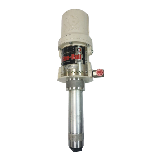
Mini Fire-Ball 225, 3:1 Bare Oil Pump, Part 246775
540 psi (3.7 MPa, 37 bar) Maximum Working Pressure
180 psi (1.24 MPa, 12.4 bar) Maximum Air Input Pressure
Fire-Ball 300, 5:1, Bare Oil Pump, Part 203876
900 psi (6.2 MPa, 62 bar) Maximum Working Pressure
180 psi (1.24 MPa, 12.4 bar) Maximum Air Input Pressure
Fire-Ball 425, 3:1, Bare Oil Pump, Part 237526
540 psi (3.7 MPa, 37 bar) Maximum Working Pressure
180 psi (1.24 MPa, 12.4 bar) Maximum Air Input Pressure
Fire-Ball 425, 6:1, Bare Oil Pump, Part 238108
1100 psi (7.6 MPa, 76 bar) Maximum Working Pressure
180 psi (1.24 MPa, 12.4 bar) Maximum Air Input Pressure
Fire-Ball 425, 10:1, Bare Oil Pump, Part 205626
1800 psi (12.4 MPa, 124 bar) Maximum Working Pressure
180 psi (1.24 MPa, 12.4 bar) Maximum Air Input Pressure
Important Safety Instructions
Read all warnings and instructions in this manual.
Save these instructions.
Parts/Materials required
Time required to rebuild pump
Graco Inc. P.O. Box 1441 Minneapolis, MN 55440-1441
Copyright 2004, Graco Inc. is registered to I.S. EN ISO 9001
Oil Pumps
®
See
page 5
1 hour
309869C
Advertisement
Table of Contents

Related Manuals for Graco Fire-Ball 246775


Summary of Contents for Graco Fire-Ball 246775
- Page 1 Read all warnings and instructions in this manual. Save these instructions. Parts/Materials required page 5 Time required to rebuild pump 1 hour Graco Inc. P.O. Box 1441 Minneapolis, MN 55440-1441 Copyright 2004, Graco Inc. is registered to I.S. EN ISO 9001...
-
Page 2: Table Of Contents
Part 203876, 300 Pump Parts List ... . 40 Graco Standard Warranty ....50 Part 237526, 425 (3:1) Pump Parts List . -
Page 3: Manual Conventions
Check equipment daily. Repair or replace worn or damaged parts immediately. • Do not alter or modify equipment. • Use equipment only for its intended purpose. Call your Graco distributor for information. • For professional use only. • Route hoses and cables away from traffic areas, sharp edges, moving parts, and hot surfaces. - Page 4 Warning WARNING SKIN INJECTION HAZARD High-pressure fluid from gun, hose leaks, or ruptured components will pierce skin. This may look like just a cut, but it is a serious injury that can result in amputation. Get immediate surgical treatment. • Do not point gun at anyone or at any part of the body.
-
Page 5: Before You Start
They include the training guides which provide theory and understanding of how the Fire-Ball pumps work. Refer to www.graco.com for additional information. You must have the following tools and repair kit prior to rebuilding or repairing the Fire-Ball pump. Order repair kits and special tools from Graco Inc. • Utility Knife • 1 Gallon Bucket •... -
Page 6: Pressure Relief Procedure
Pressure Relief Procedure Pressure Relief Procedure WARNING This equipment stays pressurized until pressure is manually relieved. Read PRESURIZED EQUIPMENT HAZARD warnings beginning on page 1. Close the pump air regulator (C) and the bleed-type master air valve (A) (required in your sys- tem). -
Page 7: Service And Repair
Service and Repair Service and Repair WARNING Read warnings beginning on page Prior to rebuilding the pump remove it from production. To do this: 1. Flush the pump, and relieve the pressure. Follow the pressure relief procedure on page 2. Disconnect the ground wire from the ground screw (14) if equipped. - Page 8 Service and Repair 3. Use a strap wrench or chain wrench on the fluid cylinder (41) to screw it out of the air motor base (28). 4. Pull the fluid cylinder (41) off. 5. Remove the valve housing (42). 309869C...
- Page 9 Service and Repair 6. Remove ball retainer and inspect the metallic ball (8), ball retainer (44), and seat of valve housing (42) for damage. 7. Remove and replace the o-ring packing (21*). 8. Screw the valve housing (42) into the fluid cylinder (41) and hand tighten.
- Page 10 Service and Repair 9. Pull the displacement rod (29) down. 10. Using wrenches on the flats of the displacement rod (29) and on the flats of the fluid piston (43), unscrew the fluid piston from the displacement rod. 11. Remove the metallic ball from the end of the displacement rod (29).
- Page 11 Service and Repair 12. Remove the packing o-ring (11*) from the fluid piston (43). 13. Unscrew the cylinder cap nut (39) from the top of the air motor cylin- der (35). 14. Pull up on the cylinder cap nut (39) to expose the trip rod (40).
- Page 12 Service and Repair 15. Grasp the trip rod (40) with pad- ded pliers. See page 5 for part numbers. CAUTION Do not damage the plated surface of the trip rod (40). Damaging the sur- face of the trip rod can result in erratic motor operation.
- Page 13 Service and Repair 18. Remove the six hex head screws holding the air motor plate identification (46) to the air motor base (28). 19. Remove the six hex head screws holding the warning plate (47) to the air motor base (28). 20.
- Page 14 Service and Repair 21. Carefully pull the air motor cylin- (35) straight off of the air motor piston (34). CAUTION To avoid damaging the cylinder wall, pull the cylinder straight off of the pis- ton. Never tilt the cylinder while you are removing it.
- Page 15 Service and Repair 24. Remove the block packing (16*) from the bottom of the air motor base (28). 25. Remove the o-ring packing (13*) from the air motor base. XXXX 26. Clamp the air motor piston (34) an upright position. 309869C...
- Page 16 Service and Repair 27. Remove the o-ring packing (18*) from the air motor piston (34). 28. Use a screwdriver handle to push down the trip rod yoke (23) snap the toggle arms (38) down. WARNING To reduce the risk of pinching or amputating your fingers, always keep fingers clear of the toggle assem- blies.
- Page 17 Service and Repair 30. Swing the toggle assembly up and away from the piston lugs, and remove the assembly. 31. Remove the toggle pins (36) from the trip rod yoke (23). 32. Straighten the lockwires (25*). 309869C...
- Page 18 Service and Repair 33. Remove the lockwires (25*) from the valve nuts (24*). 34. Screw the top valve nuts off (24*). 35. Pull the valve assembly out of the piston. 309869C...
- Page 19 Service and Repair 36. Remove the trip rod (40), trip rod yoke (23), and valve actuator (27). 37. To remove the valve poppets (31*) cut them with a sharp knife or side cutter. 38. To remove the lower valve grom- mets (17*) cut them off with a...
- Page 20 Service and Repair 39. Unscrew and remove the bottom valve nuts (24*) and the poppet valve (32). Disassembly is complete. 309869C...
-
Page 21: Cleaning And Servicing
Cleaning and Servicing Cleaning and Servicing WARNING Read warnings beginning on page 1. Clean all the parts carefully in a compatible solvent and inspect for wear or damage. Use all the repair kit parts during reassembly, and replace other parts as neces- sary. -
Page 22: Reassembly
Reassembly Reassembly CAUTION When reassembling be sure that all moving parts are greased thoroughly to prevent unnecessary wear. 1. Clamp the displacement rod (29) upright in the vise by closing the vise jaws on the flats of the dis- placement rod. 2. - Page 23 Reassembly 3. Pull the new poppet valves (31*) into the valve actuator (27). 4. Clip off the top parts of the valve poppets (31*) shown with dotted lines. 5. Place the poppet valves (32*) the air motor piston (34). 309869C...
- Page 24 Reassembly 6. Thread the bottom valve nuts (24*) onto the stems of the poppet valves until there are a few threads left before the threads run out. If you thread the valve nuts too far down onto the poppet valves, they will run off of the threaded part.
- Page 25 Reassembly 9. Check that the valve actuator (27) is aligned by the spring clips (26), and slides easily into them. Replace the spring clips (26) worn or bent. 10. Thread the top valve nuts (24*) onto the stems of the poppet valves (32*) until snug.
- Page 26 Reassembly 12. Place the toggle arm (38) ends of the toggle assembly onto the tog- gle pins (36), and snap the pivot pin ends of the toggle assembly into the piston lugs. 13. Set gap using the gap adjustment tool*. *Use part no.
- Page 27 Reassembly 15. Align the holes in the valve nuts (24*) and the slots on the stems of the poppet valves (32*) and install the lock wires (25*) through the holes in the top and bottom valve nuts. For more detail see .
- Page 28 Reassembly 18. Grease and install the new o-ring packing (13*). 19. Grease and install the new o-ring packing (12*). 20. Install the new block packing (16*) through the bottom of the air motor base (28), with the lips fac- ing toward the bottom of the pump.
- Page 29 Reassembly 21. Clamp the air motor base (28) in a vise by closing the vise jaws below the flange. 22. Grease the outside of the air motor piston (34) and displace- ment rod (29). 23. Slide the displacement rod (29) through the packings, and slide the air motor piston (34)
- Page 30 Reassembly 24. Carefully slide the air motor cylin- (35) straight onto the air motor piston (24). CAUTION To avoid damaging the air motor cyl- inder wall, slide the cylinder straight onto the piston. Never tilt the cylinder while you are replacing it. 25.
- Page 31 Reassembly 27. Tighten the cylinder cap nut (39). 28. Screw the cylinder cap (39) onto the top of the cylinder. 29. Replace the six hex head screws holding the air motor plate identification (46) onto the air motor base (28). 309869C...
- Page 32 Reassembly 30. Replace the six screws holding the warning plate (47) onto the air motor base (28). 31. Place the ball into the dis- placement rod (29). 32. Install the new o-ring packing (11*) onto the fluid piston. 309869C...
- Page 33 Reassembly 33. Clean the threads of the fluid pis- (43) and apply Loctite to the threads. Loctite will not work on oily threads. Be sure to clean threads. 34. Thread the fluid piston (43) onto the displacement rod (29). Torque to 40 to 60 ft-lb (54 to 81 N.m).
-
Page 34: Reinstalling The Fire-Ball Pump
Reinstalling the Fire-Ball Pump Reinstalling the Fire-Ball Pump Replacing the pump back into production. WARNING Read warnings beginning on page 3. Never operate the pump with the warning plates (47) or the identification plate (46) removed. These plates protect your fin- gers from getting pinched or amputated by moving parts in the air motor. -
Page 35: Troubleshooting
Troubleshooting Troubleshooting WARNING Read warnings beginning on page Check all other possible problems and solutions before disassembling the pump. Before you trouble- shoot problems using the table below, relieve the pressure and disconnect the pump fluid line. If the pump starts when the air is turned on again, the fluid line, dispensing valve, etc., is clogged. - Page 36 Troubleshooting 309869C...
- Page 37 309869C...
-
Page 38: Air Motor And Pump Lower
Air Motor and Pump Lower Air Motor and Pump Lower LIPS 425 Pumps Only The 425 pump series has an air exhaust muffler (A) instead of muffler plates (46, 47) that Models 225 and 300 have. The 425 pump models also have a piston washer that Models 225 and 300 do not have. -
Page 39: Part 246775, 225 Mini-Fire-Ball Pump Parts
Part 246775, 225 Mini-Fire-Ball Pump Parts Part 246775, 225 Mini-Fire-Ball Pump Parts Ref. Qty. Ref. Qty. No. Part No. Description No. Part No. Description 31* 15C267 POPPET, valve 100400 BALL, metallic 32* 248211 VALVE, poppet** 100078 SCREW, thread forming, hex head 15C270 PISTON, motor, air 2-1/4”... -
Page 40: Part 203876, 300 Pump Parts List
Part 203876, 300 Pump Parts List Part 203876, 300 Pump Parts List Ref. Qty. Ref. Qty. No. Part No. Description No. Part No. Description 31* 170709 POPPET, valve 100279 BALL, metallic 32* 236079 VALVE, poppet*** 100078 SCREW, thread forming, hex head 160614 PISTON, motor, air 101190 BALL, metallic 160613 CYLINDER, motor, air... -
Page 41: Part 237526, 425 (3:1) Pump Parts List
Part 237526, 425 (3:1) Pump Parts List Part 237526, 425 (3:1) Pump Parts List Ref. Qty. Ref. Qty. No. Part No. Description No. Part No. Description 190229 BASE, air motor 101178 BALL, piston; metallic 190233 ROD, piston 108001 BALL, sst 31* 170709 POPPET, exhaust valve** 101578 SCREW, cap, hex hd 32* 236079 VALVE, poppet... -
Page 42: Part 238108, 425 (6:1) Pump Parts List
Part 238108, 425 (6:1) Pump Parts List Part 238108, 425 (6:1) Pump Parts List Ref. Qty. Ref. Qty. No. Part No. Description No. Part No. Description 158359 ACTUATOR, valve, air 101190 BALL, piston; metallic 190927 BASE, air motor 101178 BALL, sst 193799 ROD, piston 101578 SCREW, cap, hex hd 31* 170709 POPPET, exhaust valve... -
Page 43: Part 205626, 425 (10:1) Pump Parts List
Part 205626, 425 (10:1) Pump Parts List Part 205626, 425 (10:1) Pump Parts List Ref. Qty. Ref. Qty. No. Part No. Description No. Part No. Description 158359 ACTUATOR, valve, air 100279 BALL, piston; metallic 191544 BASE, air motor 101190 BALL, sst 191545 ROD, piston 101578 SCREW, cap, hex hd 31* 170709 POPPET, exhaust valve... -
Page 44: 225 (3:1) Technical Data
225 (3:1) Technical Data 225 (3:1) Technical Data (Data measured with 10 weight oil @70°F (21°C) Fluid to air ratio ............3:1 Dry suction lift (feet of water)........23 Cycles/gallon (cycles/liter) ......43.5 (11.4) Wetted materials ... steel, polyurethane, aluminum, buna-N, Rulon ®... -
Page 45: 300 (5:1) Technical Data
300 (5:1) Technical Data 300 (5:1) Technical Data (Data measured with 10 weight oil @70°F (21°C) Fluid to air ratio ............5:1 Dry suction lift (feet of water)........26 Cycles/gallon (cycles/liter) ......28.4 (8.6) Wetted materials ............steel, polyurethane, aluminum, buna-N Fluid flow @80 cpm (gpm/lpm) ......2.8 (9.3) Air inlet port size..........3/8 in. -
Page 46: 425 (3:1) Technical Data
425 (3:1) Technical Data 425 (3:1) Technical Data (Data measured with 10 weight oil @70°F (21°C) Fluid to air ratio ............3:1 Dry suction lift (feet of water) ........26 Cycles/gallon (cycles/liter) ........ 6.0 (1.6) Wetted materials . steel, polyurethane, aluminum, nitrile Fluid flow @80 cpm (gpm/lpm) ..... -
Page 47: 425 (6:1) Technical Data
425 (6:1) Technical Data 425 (6:1) Technical Data (Data measured with 10 weight oil @70°F (21°C) Fluid to air ratio ............6:1 Dry suction lift (feet of water)........23 Cycles/gallon (cycles/liter) ......12.0 (3.2) Wetted materials . steel, polyurethane, aluminum, nitrile Fluid flow @80 cpm (gpm/lpm) ....... 6.6 (25.3) Air inlet port size..........1/2 in. -
Page 48: 425 (10:1) Performance Chart
425 (6:1) Technical Data 425 (10:1) Technical Data (Data measured with 10 weight oil @70°F (21°C) Fluid to air ratio............10:1 Dry suction lift (feet of water) ........26 Cycles/gallon (cycles/liter)......19.6 (5.2) Wetted materials ..steel, polyurethane, aluminum, nitrile Fluid flow @80 cpm (gpm/lpm)....... 4.1 (15.4) Air inlet port size ......... -
Page 49: Notes
Notes Notes 309869C... -
Page 50: Graco Standard Warranty
With the exception of any special, extended, or limited warranty published by Graco, Graco will, for a period of twelve months from the date of sale, repair or replace any part of the equipment determined by Graco to be defective.