Graco SaniForce 2150 Repair Parts
Electric-operated diaphragm pumps
Hide thumbs
Also See for SaniForce 2150:
- Operation (54 pages) ,
- Operation manual (52 pages) ,
- Repair parts (34 pages)
Advertisement
Quick Links
Repair/Parts
SaniForce® 2150,
SaniForce®
SaniForce®
Electric
Electric - - - Operated
Electric
Operated Diaphragm
Operated
2 2 2 - - - Inch,
Inch, 3 3 3 - - - Inch,
Inch, and
and 4 4 4 - - - Inch
Inch,
Inch,
and
Not approved
approved for
for use
use in in in explosive
Not
Not
approved
for
use
stated. See
See Approvals
Approvals page
stated.
stated.
See
Approvals
Important
Important Safety
Important
Safety
Safety Instructions
Read all warnings and instructions in this manual and in your
Operation manual before using the equipment. Save
instructions.
instructions.
instructions.
For maximum working pressure, see
Technical Specification sheets.
See page 10 for approvals.
2150, 3000,
3000, 4000,
2150,
3000,
Diaphragm Pump
Diaphragm
Inch pumps
pumps with
with electric
electric drive
Inch
pumps
with
electric
explosive atmospheres
atmospheres or or or hazardous
explosive
atmospheres
page for
for more
more information.
information. For
page
for
more
information.
Instructions
Instructions
PROVEN QUALITY. LEADING TECHNOLOGY.
4000,
4000,
Pump
Pump
drive for
for fluid
fluid transfer
transfer applications.
drive
for
fluid
transfer
hazardous (classified)
(classified) locations
hazardous
(classified)
For professional
professional use
use only.
For
professional
use
Save
Save these
these
these
3A5133M
3A5133M
3A5133M
applications.
applications.
locations unless
unless otherwise
locations
unless
only.
only.
EN
EN
EN
otherwise
otherwise
Advertisement

Related Manuals for Graco SaniForce 2150


Summary of Contents for Graco SaniForce 2150
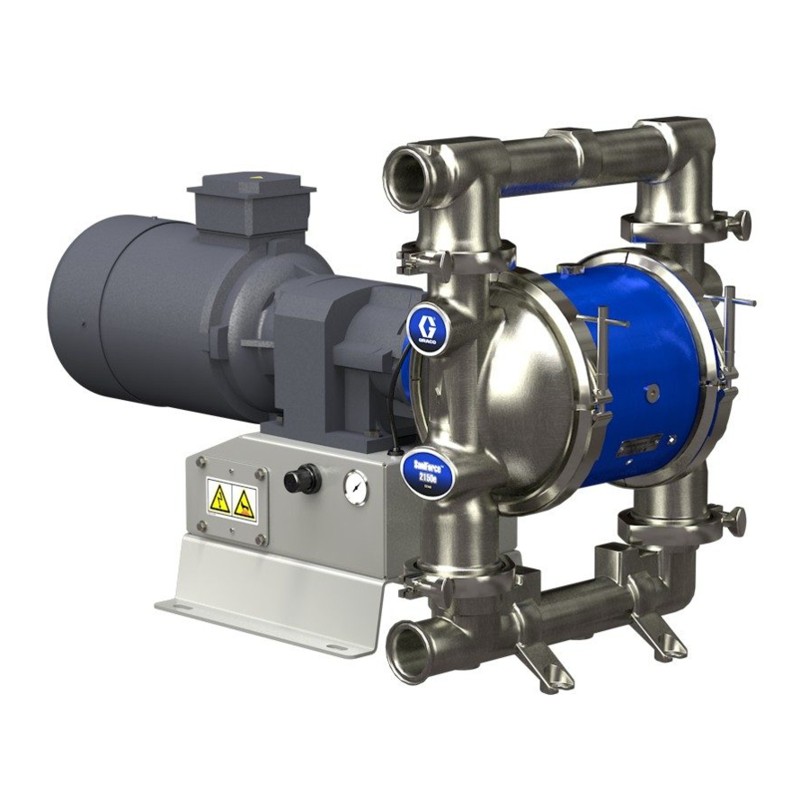
- Page 1 Repair/Parts SaniForce® 2150, 2150, 3000, 3000, 4000, 4000, SaniForce® SaniForce® 2150, 3000, 4000, 3A5133M 3A5133M 3A5133M Electric Electric Electric - - - Operated Operated Diaphragm Operated Diaphragm Pump Diaphragm Pump Pump 2 2 2 - - - Inch, Inch, 3 3 3 - - - Inch, Inch, and and 4 4 4 - - - Inch Inch pumps...
- Page 2 Contents Contents Contents Related Related Related Manuals Manuals ..............................2 2 2 Manuals Repair Repair.
- Page 3 Warnings Warnings Warnings Warnings The following warnings are for the setup, use, grounding, maintenance, and repair of this equipment. The exclamation point symbol alerts you to a general warning and the hazard symbols refer to procedure-specific risks. When these symbols appear in the body of this manual or on warning labels, refer back to these Warnings.
- Page 4 Warnings WARNING PRESSURIZED PRESSURIZED PRESSURIZED EQUIPMENT EQUIPMENT EQUIPMENT HAZARD HAZARD HAZARD Fluid from the equipment, leaks, or ruptured components can splash in the eyes or on skin and cause serious injury. • Follow the Pressure Pressure Relief Pressure Relief Procedure Relief Procedure Procedure when you stop spraying/dispensing and before...
- Page 5 Warnings WARNING THERMAL THERMAL THERMAL EXPANSION EXPANSION HAZARD EXPANSION HAZARD HAZARD Fluids subjected to heat in confined spaces, including lines, can create a rapid rise in pressure due to the thermal expansion. Over-pressurization can result in equipment rupture and serious injury.
- Page 6 Configuration Number Matrix for 2150 FG Pumps Configuration Number Number Matrix Matrix for for 2150 2150 FG FG Pumps Pumps Configuration Configuration Number Matrix 2150 Pumps Check the identification plate (ID) for the Configuration Number of your pump. Use the following matrix to define the components of your pump.
- Page 7 Configuration Number Matrix for 2150 FG Pumps Fluid Fluid Fluid Covers Covers Covers and Seat Seat Material Seat Material Ball Material Ball or or or Check Ball Check Check Diaphragm Diaphragm Material Diaphragm Material Manifold Material Manifold Manifold Certification Certification Certification Manifolds Material...
- Page 8 Configuration Number Matrix for 2150, 3000, and 4000 HS Pumps Configuration Number Number Matrix Matrix for for 2150, 2150, 3000, 3000, and and 4000 4000 Configuration Configuration Number Matrix 2150, 3000, 4000 HS Pumps Pumps Pumps Check the identification plate (ID) for the Configuration Number of your pump.
- Page 9 Configuration Number Matrix for 2150, 3000, and 4000 HS Pumps Fluid Fluid Fluid Covers Covers Covers and Seat Seat Material Seat Material Ball Material Ball or or or Check Ball Check Check Diaphragm Diaphragm Material Diaphragm Material Manifold Material Manifold Manifold Certification Certification...
- Page 10 Approvals Approvals Approvals Approvals Approvals Approvals Approvals ✦ Pumps with motor code are approved to: II 2 G Ex h d IIB T3 Gb ✚ Pumps with motor code are approved to: II 2 G Ex h IIB T3 Gb Class I, Div 1, Group D, T3B ★...
- Page 11 Use the Online Online Diaphragm Online Diaphragm Pump Diaphragm Pump Selector Pump Selector Tool Selector Tool at at at Tool www.graco.com www.graco.com. . . Search for Selector www.graco.com Selector Selector. To Order Order Replacement Order Replacement Replacement Parts Parts Parts Please call call your your distributor.
- Page 12 Troubleshooting Troubleshooting Troubleshooting Troubleshooting • Follow the Pressure Relief Procedure, page • Check all possible problems and causes before before checking or servicing the equipment. disassembly. Problem Cause Solution Problem Problem Cause Cause Solution Solution Pump cycles but will not Pump is running too fast, causing Slow down the controller (VFD) prime and/or pump.
- Page 13 Troubleshooting Problem Cause Solution Problem Problem Cause Cause Solution Solution Air consumption is higher A fitting is loose. Tighten. Inspect thread sealant. than expected. Replace. Loose or damaged o-rings or shaft seal. Diaphragm (or backup) ruptured. Replace. Air bubbles in fluid. Suction line is loose.
- Page 14 Repair Repair Repair Repair Disassemble Disassemble the Disassemble the Ball Ball Ball Check Check Valve Check Valve Valve NOTE: When reassembling fluid section components, NOTE: NOTE: loosely assemble initially to ensure acceptable alignment. Once all components are in place, tighten 1.
- Page 15 Repair Arrow (A) must point toward outlet manifold. Radiused seating surface must face the ball (7). Large champfer on O.D. must face o-ring. 3A5133M...
- Page 16 Repair Disassemble Disassemble Disassemble the the Flapper Flapper Check Flapper Check Check Valve Valve Valve Reassemble Reassemble the Reassemble the Flapper Flapper Check Flapper Check Check Valve Valve Valve 1. Follow the Pressure Relief Procedure, page 1. Clean all parts and inspect for wear or damage. Disconnect power from the motor.
- Page 17 Repair Standard Diaphragm Diaphragm Repair Repair Standard Standard Diaphragm Repair b. Rotate the drive shaft to move the piston fully to the other side. Repeat step 4a. 5. To continue with center section disassembly, see Disassemble the Center Section, page Tools Required Required Tools...
- Page 18 Repair Reassemble Reassemble Reassemble the the Standard Standard Standard Diaphragms Diaphragms Diaphragms 4. Clean the female threads of the piston shaft NOTICE NOTICE NOTICE with a wire brush dipped in solvent to remove any residual thread locker. Apply thread-locking After reassembly, allow the thread locker to cure primer and allow it to dry.
- Page 19 Repair Overmolded Diaphragm Diaphragm Repair Repair Overmolded Overmolded Diaphragm Repair b. Rotate the drive shaft to move the piston fully to the other side. Repeat step 4a. 5. To continue with center section disassembly, see Disassemble the Center Section, page Tools Required Required Tools...
- Page 20 Repair Reassemble Reassemble Reassemble the the Overmolded Overmolded Overmolded Diaphragms Diaphragms Diaphragms 4. Clean the female threads of the piston shaft NOTICE NOTICE NOTICE with a wire brush dipped in solvent to remove any residual thread locker. Apply thread-locking After reassembly, allow the thread locker to cure primer and allow it to dry.
- Page 21 Repair Center Section Section Repair Repair Center Center Section Repair 7. Use a 3/4–16 bolt to push out the drive shaft assembly (112). You can also use the bearing bolt (106), but remove the bearing (107) first. Be sure that the groove on the drive shaft remains aligned with the markings in the center section.
- Page 22 Repair Reassemble Reassemble Reassemble the the Center Center Center Section Section Section 1. Clean and dry the center housing (101), the 5. Install o-ring (109) to the center housing (101). center of the piston (102) and the drive shaft 6. Apply anti-seize lubricant on the mating edges of (112).
- Page 23 Repair Apply medium-strength (blue) thread locker to threads. Torque to 15–25 ft-lb (20–34 N•m). Lips must face IN IN IN toward the center. Apply anti-seize lubricant liberally on the radial surfaces of the drive shaft assembly. Install the drive shaft assembly with the groove facing up.
- Page 24 Repair Disconnect Disconnect Disconnect the the Motor Motor Motor and and Gearbox Gearbox Gearbox piece with the gearbox, so begin with step 4. NOTE: Use a hoist and sling to remove motor weight NOTE: NOTE: from the gearbox during removal. 1.
- Page 25 Repair Leak Leak Leak Sensor Sensor Repair Sensor Repair Repair NOTE: A previous design of the leak sensor exists. If NOTE: NOTE: e. If the continuity tests result indicate that your leak sensor contains a jam nut, refer to manual the leak sensor is not functioning properly, 3A5133A for repair instructions.
- Page 26 Repair Install Compressor Compressor Kits Kits Install Install Compressor Kits Install Compressor Compressor Kits Kits for for HS HS Pumps Pumps Install Install Compressor Kits Pumps Follow this procedure to install your compressor kit for high-sanitary pumps. See Kits and Accessories, page 38 for compressor kit options.
- Page 27 Repair Replace the the Compressor Compressor Replace Replace Compressor To avoid injury from fire, explosion, or electric shock, all electrical wiring must be done by a qualified electrician and comply with all local codes and regulations. 1. Follow the Pressure Relief Procedure, page 2.
- Page 28 Parts Parts Parts Parts 2150FG Pump Pump 2150FG 2150FG Pump 3A5133M...
- Page 29 Parts 2150HS Ball Ball Check Check Pump Pump 2150HS 2150HS Ball Check Pump 3A5133M...
- Page 30 Parts 3000HS Flapper Flapper Pump Pump 3000HS 3000HS Flapper Pump 3A5133M...
- Page 31 Parts 4000HS Flapper Flapper Pump Pump 4000HS 4000HS Flapper Pump 3A5133M...
- Page 32 Parts Parts/Kits Quick Quick Reference Reference Parts/Kits Parts/Kits Quick Reference Use this table as a quick reference for parts/kits. Go to the pages indicated in the table for a full description of kit contents. Ref. Part Part Description Description Description Qty.
- Page 33 Parts Qty. Qty. Ref. Ref. Ref. Part Part Part Description Description Description Qty. Qty. Ref. Ref. Part Ref. Part Part Description Description Description Qty. Qty. 510490 — — — 3000HS 39b — — — 25E585 SCREW, flanged 16D245 — — — 4000HS 39c —...
- Page 34 Parts Center Center Center Section Section Section Sample Configuration Number Pump Wetted Drive Center Gear Box Motor Fluid Seats Balls Diaphragms Manifold Certifica- Model Section Section and Motor Covers Seals tion Material Material Manifolds 2150 A A A 3A5133M...
- Page 35 Parts Part Part Part Description Description Description Part Part Part Description Description Description — — — COUPLER; included with HOUSING, center, 118a assembly; includes plugs Ref 118 — — — KEY; included with Ref 118 118b 25B415 Aluminum (Axx Axx) —...
- Page 36 Parts Diaphragms Diaphragms Diaphragms Sample Configuration Number Pump Wetted Drive Center Gear Box Motor Fluid Seats Balls Diaphragms Manifold Certifica- Model Section Section and Motor Covers Seals tion Material Material Manifolds 2150 Bolt Bolt Bolt- - - Through Through Through Diaphragm Diaphragm Kits Diaphragm Kits...
- Page 37 Parts Sanitary Gasket Gasket Kits Kits Pump Sanitary Sanitary Gasket Kits Kit descriptions appear in the following order: model, seat material, ball material, diaphragm Size Part No. Material Size Size Part Part Material Material material, gasket material 2150HS-PH . For example, --,CW,EO,EP .
- Page 38 Parts Kits and and Accessories Accessories Kits Kits Accessories Center Center Center Section Section Repair Section Repair Repair Tool Tool Tool Kit Kit 25B434 25B434 25B434 Includes tools needed to remove the bearing from the center section. Bearing Puller Puller Kit Kit 17J718 17J718 Bearing...
- Page 39 Technical Specifications Technical Specifications Specifications Technical Technical Specifications SaniForce Electric Electric Double Double Diaphragm Diaphragm Pump Pump SaniForce SaniForce Electric Double Diaphragm Pump Metric Metric Metric Maximum fluid working pressure 2150 100 psi 0.69 MPa, 6.9 bar 3000HS, 4000HS 60 psi 0.41 MPa, 4.1 bar Air pressure operating range 2150...
- Page 40 Technical Specifications Voltage 3-phase 230V / 3-Phase 460V Maximum Amperage Load 19.5 A (230V) / 9.75 A (460V) IE Rating IP Rating IP55 AC, Standard CE (14A, 15A (not CE), 16A) Power 5.0 HP 3.7 kW Number of Motor Poles 4-Pole Speed 1800 rpm (60 Hz) or 1500 rpm (50 Hz)
- Page 41 Technical Specifications Number of Motor Poles 4-Pole Speed 1800 rpm (60 Hz) or 1500 rpm (50 Hz) Constant Torque Gear Ratio 26.77 Voltage 3-phase 240V / 3-Phase 415V Maximum Amperage Load 8.5 A (230V) / 5.0 A (460V) IP Rating IP56 AC, Explosionproof (04D) Power...
- Page 42 Technical Specifications Ex Ratings: Classification: “simple apparatus” in accordance with UL/EN/IEC 60079-11, clause 5.7 Class I, Group D, Class II, Group F&G, Temp Code T3B II 2 G Ex ib IIC T3 Parameters = 24 V = 280 mA = 1.3 W = 2.4 pF = 1.00 µH Noise Data...
- Page 43 Pump Pump Pump Weights Weights Weights Pump Motor/Gearbox Material Standard AC ATEX AC Flameproof AC No Gear- motor Center Model Section 2150FG Aluminum Stainless Steel 2150HS- Aluminum /3A/PH Stainless Steel 3000HS Aluminum Stainless Steel 4000HS Aluminum Stainless Steel...
- Page 44 California Proposition 65 Variable Frequency Drives (2 hp) Model Model Model Hp/kW Hp/kW Hp/kW Input Input Voltage Input Voltage Voltage Range Range Range Nominal Nominal Output Nominal Output Output Voltage Voltage Voltage † 17K696 3.0/2.2 170–264 Vac 208–240 Vac, 3 phase 17K697 3.0/2.2 340–528 Vac...
- Page 45 Notes Notes Notes Notes 3A5133M...
- Page 46 With the exception of any special, extended, or limited warranty published by Graco, Graco will, for a period of twelve months from the date of sale, repair or replace any part of the equipment determined by Graco to be defective.