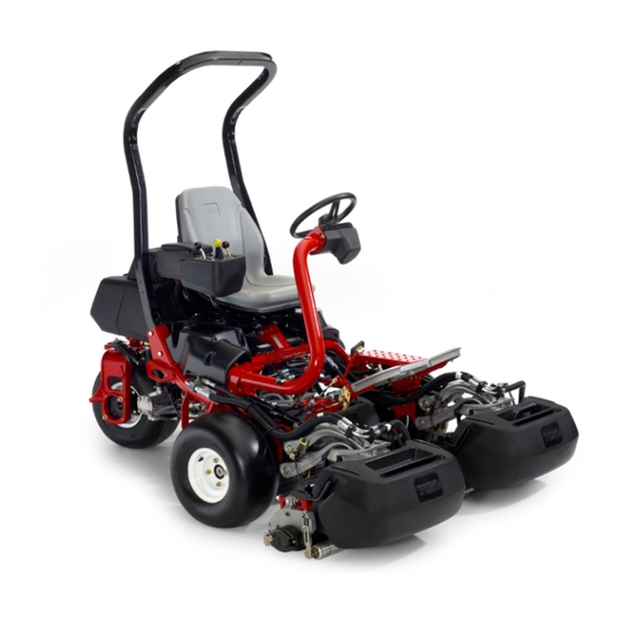
Toro Greensmaster TriFlex 3400 Operator's Manual
Traction unit
Hide thumbs
Also See for Greensmaster TriFlex 3400:
- Operator's manual (48 pages) ,
- Manual (334 pages) ,
- Service manual (332 pages)

Related Manuals for Toro Greensmaster TriFlex 3400


Summary of Contents for Toro Greensmaster TriFlex 3400
- Page 1 Form No. 3437-387 Rev A Greensmaster ® 3400 TriFlex ® Traction Unit Model No. 04520—Serial No. 405700000 and Up *3437-387* A Register at www.Toro.com. Original Instructions (EN)
- Page 2 It is a violation of California Public Resource Code Whenever you need service, genuine Toro parts, or Section 4442 or 4443 to use or operate the engine on additional information, contact an authorized Toro...
-
Page 3: Table Of Contents
Contents Electrical System Safety ........37 Servicing the Battery......... 37 Locating the Fuses ........... 37 Safety ............... 4 Drive System Maintenance ........38 General Safety........... 4 Checking the Tire Pressure....... 38 Safety and Instructional Decals ......4 Checking the Torque of the Wheel Setup ................ -
Page 4: Safety
Safety • Do not operate the machine without all guards and other safety protective devices in place and functioning properly on the machine. This machine has been designed in accordance with • Keep bystanders and children out of the operating EN ISO 5395 and ANSI B71.4-2017 and meets these area. - Page 5 decal115-8203 decal119-9346 115-8203 119-9346 1. Read the Operator's 2. Radiator fan—50 A 1. Press the pedal to unlock. 2. Read the Operator's Manual for fuse Manual for more information. information. decal131-2046 131-2046 1. Double lights 3. Off 2. Single light decal133-8062 133-8062 decal115-8226...
- Page 6 decal136-8506 decal136-8505 136-8506 136-8505 Note: This machine complies with the industry standard 1. Warning—read the 4. Tipping hazard—slow the stability test in the static lateral and longitudinal tests with the Operator’s Manual; do machine before turning; maximum recommended slope indicated on the decal. Review the not operate this machine do not turn at high speeds.
- Page 7 decal139-6492 139-6492 1. Read the Operator’s 2. Low hydraulic fluid level Manual before performing indicator maintenance. decal115-8156 115-8156 1. Reel height 3. 8–blade cutting unit 5. 14–blade cutting unit 7. Fast 2. 5–blade cutting unit 4. 11–blade cutting unit 6. Reel speed 8.
- Page 8 decal139-6493 139-6493 1. Lower and engage the reels. 8. Reel—mow 2. Raise and disengage the reels. 9. Reel—backlap 3. Mow direction 10. Choke 4. Fast 11. Engine—start 5. Slow 12. Engine—run 6. Neutral 13. Engine—stop 7. Reel—transport...
-
Page 9: Setup
Bolt (1/2 x 3-3/4 inches) Install the roll bar. Flange nut (1/2 inch) Seat Kit (order separately; contact your Install the seat to the base. authorized Toro distributor) Service decal (Part No. 139-2728) Install the service and clip decals. Clip decal (115-8156) Steering wheel Locknut (1-1/2 inches) Install the steering wheel. -
Page 10: Installing The Roll Bar
Installing the Seat Parts needed for this procedure: Parts needed for this procedure: Roll bar Seat Kit (order separately; contact your authorized Toro distributor) Bolt (1/2 x 3-3/4 inches) Flange nut (1/2 inch) Procedure Procedure Acquire your desired seat kit from your distributor and Remove the top crate support from the crate. -
Page 11: Installing The Steering Wheel
Installing the Steering Wheel Parts needed for this procedure: Steering wheel Locknut (1-1/2 inches) Washer Steering-wheel cap g291701 Figure 4 Premium Seat (Model No. 04719) Procedure 1. Service decal 3. 2.5 cm (1 inch) Slide the steering wheel onto the steering shaft 2. -
Page 12: Activating And Charging The Battery
Activating and Charging the Battery No Parts Required Procedure g005080 Figure 7 Use only electrolyte (1.265 specific gravity) to fill the battery initially. Carefully fill each cell with electrolyte until the plates are covered with about 6 mm (1/4 inch) DANGER of fluid (Figure... -
Page 13: Installing The Oil Cooler
When the battery is charged, disconnect the charger from the electrical outlet and battery posts. Note: After the battery has been activated, Installing the Oil Cooler add only distilled water to replace normal loss, although maintenance-free batteries should not require water under normal operating conditions. Optional Important: Failure to correctly activate the... -
Page 14: Installing The Grass-Basket Hooks
Installing the Grass-Basket Installing the Cutting Units Hooks Parts needed for this procedure: Gauge bar Parts needed for this procedure: Cutting unit (obtain from your authorized Toro Grass-basket hook distributor) Flange bolts Grass basket Procedure Procedure Install the 6 grass-basket hooks onto the ends of the Prepare the cutting units for installation;... -
Page 15: Installing The Ce Guard Kit
Installing the CE Guard Kit Parts needed for this procedure: CE Guard Kit―Part No. 04442 (sold separately) g233420 Procedure Figure 11 Install the CE Guard Kit; refer to the CE Guard Kit for 1. CE mark decal Greensmaster 3400 TriFlex Traction Unit Installation Instructions. -
Page 16: Reducing The Tire Pressure
Product Overview Reducing the Tire Pressure No Parts Required Procedure The tires are overinflated at the factory for shipping purposes. Reduce the pressure to the proper levels before starting the machine; refer to Checking the Tire Pressure (page 38). Burnishing the Brakes g014674 Figure 13 No Parts Required... - Page 17 Steering-Arm-Locking Pedal Press the pedal (Figure 14) and raise or lower the steering arm for operator comfort, then, release the pedal to lock the arm in place. Throttle Lever Use the throttle lever (Figure 16) to control the speed of the engine. Move the throttle lever toward the F position to increases the engine speed;...
- Page 18 Functional Control Lever Hour Meter The hour meter (Figure 17) indicates the total hours The functional control lever (Figure 16) provides 2 traction selections plus a N position. You can the machine has operated. It starts to function EUTRAL shift from mow to transport or transport to mow (not whenever you rotate the ignition switch to the O to neutral) while the machine is in motion;...
- Page 19 Backlap Lever Seat-Adjusting Lever The backlap lever is located under the plastic cover to The seat-adjusting lever is located on the front, left the left of the seat. Use the backlap lever (Figure corner of the seat (Figure 21), allowing you to adjust in conjunction with the raise/lower mow control lever the seat forward and rearward.
-
Page 20: Specifications
Figure 22 your Authorized Service Dealer or authorized Toro 1. Fuel shutoff (under the fuel tank) distributor or go to www.Toro.com for a list of all approved attachments and accessories. To ensure optimum performance and continued safety certification of the machine, use only genuine Toro replacement parts and accessories. -
Page 21: Before Operation
• Use extreme care in handling fuel. It is flammable time after converting to biodiesel blends. and its vapors are explosive. ◊ Contact your authorized Toro distributor for • Extinguish all cigarettes, cigars, pipes, and other more information on biodiesel. -
Page 22: Filling The Fuel Tank
Filling the Fuel Tank During Operation Clean around the fuel-tank cap and remove it (Figure 23). During Operation Safety General Safety • The owner/operator can prevent and is responsible for accidents that may cause personal injury or property damage. • Wear appropriate clothing, including eye protection;... -
Page 23: Breaking In The Machine
• – Shut off the engine and remove the key. Use extreme caution when operating the machine near drop-offs, ditches, embankments, water – Wait for all movement to stop. hazards, or other hazards. The machine could • Operate the machine only in good visibility and suddenly roll over if a wheel goes over the edge appropriate weather conditions. -
Page 24: Checking The Machine After Starting The Engine
If fluid leaks continue to appear, contact Turn the ignition key to the S position. TART your authorized Toro distributor for assistance and, if necessary, replacement parts. Important: To prevent overheating of the starter motor, do not engage the starter... -
Page 25: Driving The Machine Without Mowing
The safety-interlock system prevents the reels from The engine should shut off, which indicates operating unless the functional-control lever is in the that the interlock system is operating correctly. position. Correct the problem if it is not operating properly. Checking the Traction Pedal Checking the Raise/Lower Mow Control Perform the following system checks daily to ensure... - Page 26 to lay down and therefore be difficult to trap between which quickly lines the machine up for your next the reel blades and the bedknife. pass. Cutting the Green Approach the green with the functional-control lever in the M position and the throttle at full speed.
-
Page 27: After Operation
After Operation damage to the turf may result. Stopping the machine on a wet green may leave marks or indentations from the wheels. After Operation Safety Cutting the Periphery and Finishing the Job General Safety Finish cutting the green by mowing the outer •... -
Page 28: Inspecting And Cleaning After Mowing
Inspecting and Cleaning Hauling the Machine after Mowing • Use care when loading or unloading the machine into a trailer or a truck. After mowing, thoroughly wash the machine with a • Use a full-width ramp for loading the machine into garden hose without a nozzle so that excessive water a trailer or a truck. -
Page 29: Towing The Machine
Towing the Machine In case of an emergency, you can tow the machine for up to 0.4 km (1/4 mile). Important: Do not tow the machine faster than 3 to 5 km/h (2 to 3 mph) to avoid damaging the drive system. -
Page 30: Maintenance
Determine the left and right sides of the machine from the normal operating position. Note: Download a free copy of the electrical or hydraulic schematic by visiting www.Toro.com and searching for your machine from the Manuals link on the home page. -
Page 31: Recommended Maintenance Schedule(S)
Recommended Maintenance Schedule(s) Maintenance Service Maintenance Procedure Interval • Torque the wheel nuts. After the first hour • Check the tension on the alternator belt. After the first 8 hours • Torque the wheel nuts. After the first 10 hours •... -
Page 32: Daily Maintenance Checklist
Daily Maintenance Checklist Duplicate this page for routine use. Maintenance Check Item For the week of: Mon. Tues. Wed. Thurs. Fri. Sat. Sun. Check the safety-interlock operation. Check the instrument operation. Check the brake operation. Check/empty the fuel filter/water separator. Check the fuel level. -
Page 33: Engine Maintenance
3. Air-cleaner cover • Alternate oil: SAE 15W–40 2. Air filter Toro Premium Engine oil is available from your distributor in the 10W–30 viscosity. See the Parts Remove the cover from the air-cleaner body. Catalog for part numbers. Before removing the filter, use low pressure air... - Page 34 checking. If the oil level is at or below the Add mark on the dipstick, add oil to bring the oil level to the F mark. Do not overfill. Important: Keep the engine oil level between the upper and lower limits on the oil gauge; the engine may fail if you run it with too much or too little oil.
-
Page 35: Fuel System Maintenance
Fuel System Maintenance Draining Water from the Fuel Filter Service Interval: Before each use or daily Park the machine on a level surface and shut off the engine. Place a drain pan under the fuel filter. g014754 Figure 31 Open the drain plug on the fuel filter approximately one turn and drain any 1. -
Page 36: Replacing The Fuel Filter/Water Separator
Replacing the Fuel Screw the filter on by hand until the gasket contacts the filter adapter, then tighten 1/2 to 3/4 Filter/Water Separator turn further. Ensure that the filter-drain plug is closed. Open Service Interval: Every 500 hours the fuel-shutoff valve. Close the fuel-shutoff valve (Figure 34) below... -
Page 37: Electrical System Maintenance
Electrical System WARNING Incorrect battery cable routing could damage Maintenance the tractor and cables, causing sparks. Sparks can cause the battery gasses to Electrical System Safety explode, resulting in personal injury. • Always disconnect the negative (black) • Disconnect the battery before repairing the battery cable before disconnecting the machine. -
Page 38: Drive System Maintenance
If the wheel still turns when the Wheel nut torque specification: 95 to 122 N∙m (70 eccentric is at the maximum adjustment, to 90 ft-lb) contact your authorized Toro distributor Note: To ensure even distribution, torque the wheel or refer to the Service Manual for further nuts in a X pattern. -
Page 39: Adjusting The Mowing Speed
Adjusting the Mowing Speed The mow speed is set to 3.8 mph at the factory. You can adjust the forward moving speed from 0 to 8 km/h (0 to 5 mph). Loosen the jam nut on the trunnion bolt (Figure 39). -
Page 40: Cooling System Maintenance
Cooling System Clean the screen and install it. Maintenance Checking the Engine-Coolant Level Cooling System Safety The capacity of the cooling system is approximately • Swallowing engine coolant can cause poisoning; 4.6 L (4.9 US qt). keep out of reach from children and pets. Fill the cooling system with a 50/50 solution of water •... -
Page 41: Brake Maintenance
Brake Maintenance Belt Maintenance Burnishing the Brakes Adjusting the Alternator Belt Service Interval: Yearly Firmly apply the brakes and drive the machine at Service Interval: After the first 8 hours mowing speed until the brakes are hot, as indicated Ensure that the belt is properly tensioned to ensure by their smell. -
Page 42: Hydraulic System Maintenance
Biodegradable Hydraulic Fluid is the only synthetic biodegradable fluid approved by Toro. Fluid This fluid is compatible with the elastomers used in Toro hydraulic systems and is suitable for a Important: Regardless of the hydraulic fluid type wide-range of temperature conditions. This fluid is... - Page 43 Hydraulic Fluid Capacity: 25.7 L (6.8 US gallons) Position the machine on a level surface. If the fluid becomes contaminated, have your authorized Toro distributor flush the system. Note: Ensure that the machine has cooled Contaminated fluid looks milky or black when down so that the fluid is cold.
-
Page 44: Checking The Hydraulic Lines And Hoses
Cutting Unit Maintenance Checking the Hydraulic-Fluid Level (page 42). Start the machine and run it at idle for 3 to 5 Blade Safety minutes to circulate the fluid and remove any air trapped in the system. Shut off the engine and A worn or damaged blade or bedknife can break, and check the fluid level. - Page 45 g014609 Figure 47 1. Latch—closed position 3. Latch—open position g014596 Figure 45 2. Suspension-arm bar 2. Bedbar-adjusting-screw 1. Prop (not provided) nut (2) Installing the Cutting Units Lift up on the footrest and swing it open, allowing access to the center cutting unit position (Figure 46).
- Page 46 g014605 Figure 50 1. Reel motor 2. Motor-retaining bar Move the motor to the storage location on the front of the suspension arm (Figure 51). g014690 Figure 49 g014608 Figure 51 1. Reel motor 3. Cavity 2. Spline shaft 4. Motor-retaining bar Note: When sharpening, setting the height of cut, or performing other maintenance...
-
Page 47: Checking The Reel-To-Bedknife Contact
Checking the Reel-to-Bedknife Contact Each day before operating the machine, check the reel-to-bedknife contact, regardless if the quality of cut had previously been acceptable. There must be light contact across the full length of the reel and bedknife; refer to the Cutting Unit Operator’s Manual. Backlapping the Reels g014620 Figure 52... -
Page 48: Setting The Reel Speed
When finished, return the backlap levers to the (F) position, replace the cover, and ORWARD wash all lapping compound off of the cutting units. Adjust cutting unit reel to bedknife as needed. Move the cutting unit reel speed control to the desired mowing position. Important: If the backlap lever is not returned to the F... -
Page 49: Reel Speed Table
Diagnostics System the service indicator light flashes a number of times, giving you the error code that you or your authorized Toro distributor can use to identify the problem. Diagnosing the Service Note: You cannot start the engine in diagnostic mode. -
Page 50: Storage
While the engine is still warm, drain the oil from fault codes. the crankcase. Refill it with fresh oil; refer to For a list of error codes, refer to your authorized Toro Changing the Engine Oil and Filter (page 34). - Page 51 Notes:...
- Page 52 Notes:...
- Page 53 Notes:...
- Page 54 The Toro Company (“Toro”) respects your privacy. When you purchase our products, we may collect certain personal information about you, either directly from you or through your local Toro company or dealer. Toro uses this information to fulfil contractual obligations - such as to register your warranty, process your warranty claim or to contact you in the event of a product recall - and for legitimate business purposes - such as to gauge customer satisfaction, improve our products or provide you with product information which may be of interest.
- Page 55 While the exposure from Toro products may be negligible or well within the “no significant risk” range, out of an abundance of caution, Toro has elected to provide the Prop 65 warnings. Moreover, if Toro does not provide these warnings, it could be sued by the State of California or by private parties seeking to enforce Prop 65 and subject to substantial penalties.
- Page 56 Countries Other than the United States or Canada Customers who have purchased Toro products exported from the United States or Canada should contact their Toro Distributor (Dealer) to obtain guarantee policies for your country, province, or state. If for any reason you are dissatisfied with your Distributor's service or have difficulty obtaining guarantee information, contact your Authorized Toro Service Center.