
Related Manuals for Siemens SIMATIC NET CP 243-1


Summary of Contents for Siemens SIMATIC NET CP 243-1
-
Page 1: Table Of Contents
Preface Notes on product Table of contents List of figures List of tables Introduction Features and functions SIMATIC NET Installation and commissioning Configuration CP 243-1 Programming Communications processor for Industrial Ethernet Diagnostics Appendix A: Technical data Appendix B: Example Technical manual Appendix C: Timeout SIMATIC NET –... - Page 2 Copyright Siemens AG, 2002, All rights reserved Liability exclusion Passing this document on to third parties, reproducing this We have checked the contents of this Manual to ensure that they document or using or relating its contents is not permitted without match the hardware and software described herein.
- Page 3 Trademarks SIMATIC, SIMATIC NET, SINEC and SIMATIC NET Networking for Industry® are registered trademarks of Siemens AG. Other designations in this document may be trademarks whose use by third parties for their own purposes may infringe on the rights of the trademark holder.
- Page 4 Caution The device may only be used in applications as provided for in the catalog and in the technical description, and only in connection with non-Siemens products and compo- nents that have either been recommended or approved. Successful and safe operation of this equipment is dependent on proper transport, handling, storage, erection and installation, as well as careful operation and mainte- nance.
-
Page 5: Preface
09/02 Preface Preface Purpose of this manual This manual is designed to support you in using the CP 243-1 communications processor. You are provided with information on how to employ this communica- tions processor to communicate via Industrial Ethernet (IE). Prerequisites A prerequisite for understanding how the CP 243-1 works is familiarity with this manual and the "SIMATIC S7-200 Automation System"... -
Page 6: Notes On Product
Notes on product 09/02 Notes on product Address label: MAC address The CP 243-1 is delivered with a fixed MAC address. The MAC address is affixed to the underside of the top cover of the device. MLFB number, scope of delivery Product name MLFB Scope of delivery... -
Page 7: Table Of Contents
09/02 Table of contents Table of contents Preface....................... 1 Notes on product ....................2 List of figures....................5 List of tables ..................... 6 Introduction ....................7 Features and functions................9 Overview ......................9 S7 communication via Industrial Ethernet ............10 2.2.1 Application...................... - Page 8 Table of contents 09/02 Configuring a CP 243-1 from a user program............ 36 4.4.1 Occupied system flag area (SM area) ............... 37 4.4.2 Structure of the Configuration Data Blocks (CDB)..........38 4.4.3 Structure of the Network Parameter Blocks (NPB)..........42 4.4.4 Structure of the Network Data Blocks (NDB) .............
-
Page 9: List Of Figures
09/02 List of figures List of figures Fig. 1. System overview ..................... 12 Fig. 2. Connections ......................17 Fig. 3. Front with LED displays ..................18 Fig. 4. Space requirements for installation................. 23 Fig. 5. Dimensions for installation in a control panel............24 Fig. -
Page 10: List Of Tables
List of tables 09/02 List of tables Table 1: Functions of individual LED displays............... 19 Table 2: System flag area ..................... 37 Table 3: CDB structure......................41 Table 4: NPB structure ......................42 Table 5: NDB structure......................44 Table 6: Configuration of read/write commands .............. -
Page 11: Introduction
09/02 Introduction Introduction Definition and application The CP 243-1 is a communications processor designed for operation in an S7-200 automation system. It is used for connecting an S7-200 system to Industrial Ethernet (IE). The CP 243-1 also facilitates communication via Ethernet for the low-end performance range of the S7 product family. - Page 12 Introduction 09/02 The CP 243-1 software is compatible with the following standards: • S7 XPUT/XGET and S7 READ/WRITE • S7-200 I/O bus specifications Planning The CP 243-1 is configured using STEP 7 Micro/WIN 32, version 3.2.1. or higher. The CP 243-1 is always delivered with a fixed MAC address. The IP address and the subnet mask either must be configured or they must be retrieved from a BOOTP server via the BOOTP protocol.
-
Page 13: Features And Functions
09/02 Features and functions Features and functions Overview The CP 243-1 features the following functions: • S7 communication − Performant data communication via Industrial Ethernet. Communication is based on standard TCP/IP − Ethernet access via an RJ45 socket − Simple connection to an S7-200 system via the S7-200 backplane bus −... -
Page 14: S7 Communication Via Industrial Ethernet
Features and functions 09/02 S7 communication via Industrial Ethernet 2.2.1 Application The S7 communication via Industrial Ethernet makes program-controlled commu- nication via communication SFBs/FBs and configured S7 connections possible. The CP 243-1 supports S7 communication via Industrial Ethernet by means of the XPUT/XGET and READ/WRITE services. -
Page 15: Communications Processor
09/02 Features and functions 2.2.2 Types of communication The CP 243-1 is provided with three types of communication relationships that can be applied either individually or in combination. 1. Connection to STEP 7 Micro/WIN 32 2. Connection to further, remote components of the SIMATIC S7 family 3. -
Page 16: For Industrial Ethernet
Features and functions 09/02 Overview: S7-200 Micro/WIN BOOTP max. 8 x xput / xget read / write Ethernet OPC-Server OPC-Client S7-200 S7-300 S7-400 Fig. 1. System overview You can have a CPU 22x with CP 243-1 communicate with other S7-200, S7-300 and S7-400 systems, as well as with an OPC server. - Page 17 09/02 Features and functions Data exchange via Industrial Ethernet The exchange of data via the CP 243-1 is based on Ethernet and is therefore not deterministic, i.e. response times cannot be guaranteed. Network support is pro- vided for 10 and 100 Mbit networks, each in full-duplex and half-duplex mode. Furthermore, the CP 243-1 supports the "Auto Negotiation"...
- Page 18 Features and functions 09/02 S7 communication The S7 services, XPUT and XGET, are used for data exchange between two con- trollers. Here, the CP 243-1 can be implemented as both a client and a server. Communication between a CP 243-1 and an OPC server running on a PC/PG is based on the S7 services, READ and WRITE.
-
Page 19: Security
09/02 Features and functions Security 2.3.1 Configuration The CP 243-1 configuration is stored in the S7-200 CPU as non-volatile data. The validity of the configuration is ensured using a CRC mechanism. When a CP 243-1 configuration is stored, STEP 7 Micro/WIN 32 calculates a CRC checksum. -
Page 20: Data Security
Features and functions 09/02 2.3.2 Data security The CP 243-1 represents a physical connection between Ethernet and the S7-200 I/O bus. Therefore, it offers: • no protection against intentional or unintentional manipulation of data areas and/or system status of the local or remote CPUs •... -
Page 21: Connections
09/02 Features and functions Connections Front view: Integrated ribbon cable with socket for I/O bus Connector for I/O bus 8-pin RJ45 socket for Terminal block for 24 V DC supply Ethernet connection voltage and ground connection Fig. 2. Connections The CP 243-1 has the following connections: •... -
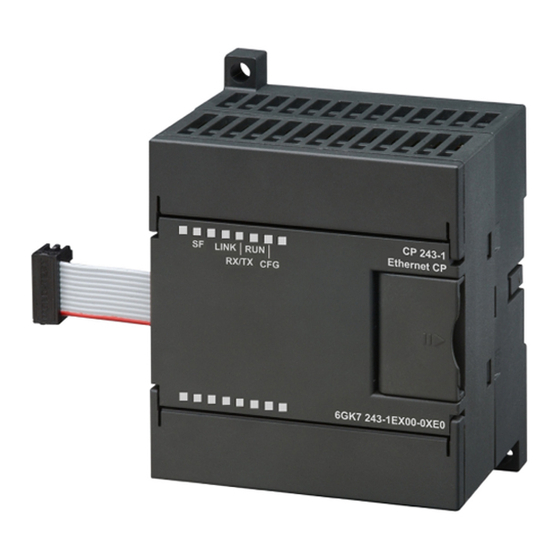
Page 22: Displays: Front Leds
Features and functions 09/02 Displays: Front LEDs Fig. 3. Front with LED displays Five LEDs are located on the front to indicate: LED display Color Meaning System error: Red, continuous Lights up when an error occurred System error: Red, flashes Flashes (approx. -
Page 23: Table 1: Functions Of Individual Led Displays
09/02 Features and functions LED display Color Meaning Green, continuous Operational: The CP 243-1 is ready for communication Yellow, continuous Configuration: Lights up when STEP 7 Micro/WIN 32 actively main- tains a connection to the S7-200 CPU via the CP 243-1 Table 1: Functions of individual LED displays While the CP243-1 is booting, the SF LED blinks twice. -
Page 24: Installation And Commissioning
Installation and commissioning 09/02 Installation and commissioning Installation The devices of the S7-200 series can be installed either in a control panel or on a DIN rail. The modules can be arranged both horizontally and vertically. The S7-200 CPU and the extension modules are designed to naturally dissipate heat by means of convection. -
Page 25: General Guidelines
09/02 Installation and commissioning General guidelines General guidelines to follow when wiring your automation system: • Ensure that all applicable and binding standards are complied with when wiring the CP 243-1. Observe the appropriate national and regional regulations when installing and operating the device. Inquire at local authorities regarding stan- dards and regulations that must be complied with in your particular case. -
Page 26: Electrical Requirements
Installation and commissioning 09/02 Electrical requirements The input voltage must always be equal to 24 V DC. Only apply 24 V DC voltage from power sources that are reliably electrically iso- lated from 120/230 V AC sources and similar sources of danger. Reliable electrical isolation is defined, for example, in the following standards: −... -
Page 27: Fig. 4. Space Requirements For Installation
09/02 Installation and commissioning Space requirements for installation Observe the following guidelines when installing your module: • The CP 243-1 is designed to naturally dissipate heat by means of convection. Therefore, leave a space of at least 25 mm both above and below the device to ensure adequate heat dissipation. -
Page 28: Dimensions For Installation In A Control Panel
Installation and commissioning 09/02 Dimensions for installation in a control panel The CP 243-1 is provided with drill holes that facilitate installation in a control panel. 96 mm 88 mm CP 243-1 80 mm 63,2 mm Minimum clearance of 9.5 mm between the modules when installed in 71,2 mm control cabinet using... -
Page 29: Installation In A Control Panel
09/02 Installation and commissioning Installation in a control panel Procedure / steps 1. Provide the control panel with drill holes for bolts of size DIN M4. Adhere to the notes and dimensions stated in Sections 3 and 3.1 for installation in a control panel. -
Page 30: Installation On A Standard Din Rail
Installation and commissioning 09/02 Installation on a standard DIN rail Procedure / steps 1. Open the locking latch and mount the CP 243-1 on the DIN rail immediately to the right of the CPU or over the CPU. 2. Close the locking latch to fasten the CP 243-1 onto the rail. Ensure that the latch engages properly and that the device is securely fastened to the rail. -
Page 31: Replacement Of The Cp 243-1
09/02 Installation and commissioning Note The front doors of the CP 243-1 must be kept closed during operation. The device must be installed in such a manner that the upper and lower air ducts of the module are not obstructed and that air can circulate freely. Replacement of the CP 243-1 If the CP 243-1 (6GK7 243-1EX00-0XE0) has to be replaced, reprogramming is not required since the configuration data and the user program are stored in the... -
Page 32: Configuration
Configuration 09/02 Configuration Configuration options An S7-200 system can communicate with another S7-200 system and with an S7-300, S7-400 or OPC-based system via the CP 243-1A. There are two methods of configuring a communication of this type in an S7-200 system: •... - Page 33 09/02 Configuration If an S7-200 system is to communicate with an S7-300, S7-400 or OPC-based sys- tem via a CP 243-1, configure such an S7-300, S7-400 or OPC-based system us- ing STEP 7, version 5.1 or higher, with Service Pack 3 or higher (with NCM S7 for Industrial Ethernet).
-
Page 34: Value Ranges Of The Configuration Data
Configuration 09/02 Value ranges of the configuration data 4.2.1 IP address The IP addresses to be specified at various points within the configuration must comply with the general conventions defining IP address validity. According to these conventions, certain IP addresses serve specific purposes. These addresses will not be accepted by the CP 243-1. -
Page 35: Configuring A Cp 243-1 Using Step 7 Micro/Win 32
09/02 Configuration Configuring a CP 243-1 using STEP 7 Micro/WIN 32 After you have installed and started STEP 7 Micro/WIN 32 on your PC, start the Wizard for the CP 243-1. It is located in the “Extras“ menu under the "Ethernet Wizard..."... - Page 36 Configuration 09/02 Defining the address of the control byte and the number of connections Use the next mask to specify the address of the byte in the memory address space of your S7-200 system from which the CP 243-1 can be addressed from the S7-200 CPU.
- Page 37 09/02 Configuration Note The specifications for the communications end points ("TSAPs") in STEP 7 and in STEP 7 Micro/WIN 32 must be mutually compatible. CP 243-1 J31069-D0428-U001-A1-7618...
- Page 38 Configuration 09/02 Enabling / disabling the CRC mechanism and defining the Keep Alive time Once you have configured the connections, you must specify in the next mask whether or not your configuration data on the S7-200 CPU are to be protected by a CRC mechanism against being unintentionally overwritten.
- Page 39 09/02 Configuration Defining the memory area for storing the configuration Finally, use the next mask to define the memory area in which your configuration data are to be stored on the S7-200 CPU. The Wizard will assist you in doing so. The Wizard then informs you about which subroutines it is establishing on the ba- sis of your configuration and where your configuration data are being stored.
-
Page 40: Configuring A Cp 243-1 From A User Program
Configuration 09/02 Configuring a CP 243-1 from a user program The configuration data of the CP 243-1 are stored in the S7-200 CPU memory and can therefore be changed directly from an S7-200 user program. The cyclic redun- dancy check (CRC) must be disabled for the configuration data so that the CP 243-1 will accept configuration data which were changed in this way during the next startup. -
Page 41: Occupied System Flag Area (Sm Area)
09/02 Configuration 4.4.1 Occupied system flag area (SM area) The CP 243-1 occupies 50 bytes in the S7-200 CPU system flag area. The ad- dress of these 50 bytes depends on the position in which a CP 243-1 is currently located in an S7-200 system. -
Page 42: Structure Of The Configuration Data Blocks (Cdb)
Configuration 09/02 4.4.2 Structure of the Configuration Data Blocks (CDB) The CDB is generated by the Ethernet Wizard in STEP 7 Micro/WIN 32. The fol- lowing table shows the structure of the CDB. Byte offset in Description Data format Example variables mem- Header Module name... - Page 43 09/02 Configuration Byte offset in Description Data format Example variables mem- set to 16#00000000 if BOOTP is used. 23-26 IP address of Gateway. 4 bytes hex 192.12.45.24: 16#00000000 means: do not use 16#C00C2D18 Gateway. This field should be set to 16#00000000 if BOOTP is used.
- Page 44 Configuration 09/02 Byte offset in Description Data format Example variables mem- 45-46 Remote TSAP 2 bytes hex See S7 connection 0 section. S7 connection 2 section (If not all bytes are used in this section, they should be filled in with 16#00) Flag byte 1 byte hex...
-
Page 45: Table 3: Cdb Structure
09/02 Configuration Byte offset in Description Data format Example variables mem- S7 connection 6 section (If not all bytes are used in this section, they should be filled in with 16#00) Flag byte 1 byte hex See S7 connection 0 section. -
Page 46: Structure Of The Network Parameter Blocks (Npb)
Configuration 09/02 4.4.3 Structure of the Network Parameter Blocks (NPB) This data block is generated by the CP 243-1 itself in accordance with the current set of network parameters. It contains the TCP/IP parameter values currently in use, provided the CP 243-1 has been correctly configured. In the event of a con- figuration error, the NPB will not contain any valid data. -
Page 47: Structure Of The Network Data Blocks (Ndb)
09/02 Configuration 4.4.4 Structure of the Network Data Blocks (NDB) The NDB is generated by the Ethernet Wizard in STEP 7 Micro/WIN 32. The read/write commands possible for clients are configured in this data bock. Up to 32 read/write commands can be configured for each of the 8 possible communication channels. -
Page 48: Table 5: Ndb Structure
Configuration 09/02 Byte offset in Name Description Data variables memory format COM_CHr_OFF 1 byte hex COM_CHr_LEN0 1 byte hex 1 byte hex COM_CHr_LENp 1 byte hex COM_CHr_0 ASCII ASCII COM_CHr_p ASCII CRC section The last two bytes CRC over all NDB 2 bytes hex The last two of the NDB... -
Page 49: Configuring A Communication Partner With Step 7
09/02 Configuration Configuring a communication partner with STEP 7 Using the S7-300 system as an example, the following section outlines the steps you need to take in STEP 7 to configure the system for communication with an S7-200 system via the associated Ethernet communications processor. The proce- dure for the S7-400 system is similar. -
Page 50: Fig. 7. "Properties – S7 Connection" Mask
Configuration 09/02 Configured connections If you would like to work with a configured connection, you must first insert a new S7 connection in the STEP 7 NetPro program package. In the "Insert new connec- tion" mask, specify the type of station with which you would like to establish a con- nection. - Page 51 09/02 Configuration Finally, in the "Address details" mask, define the communication end points ("TSAPs") to be used. The TSAP of a connection in the S7-200 system is found in the STEP 7 Micro/WIN 32 in the mask in which you configured the individual con- nections, under the "Local properties"...
- Page 52 Configuration 09/02 Free connections A free connection can only be used if your S7-300 or S7-400 system is to be oper- ated as a server. Free connections do not have to configured in STEP 7. Standard S7-300 and S7-400 systems are set up to communicate via free connections. If you would like to make use of the mechanism for free connections in your S7- 300 or S7-400 system, the client side for each of these connections must still be configured.
-
Page 53: Behavior Of Cp 243-1 In The Event Of Configuration Errors
09/02 Configuration Behavior of CP 243-1 in the event of configuration er- rors If the CP 243-1 recognizes an invalid configuration, it attempts to retrieve its TCP/IP address parameters (IP address, subnet mask, IP address of Gateway) via a BOOTP service. The CP 243-1 continues the attempt for approx. 1 minute. If it does not receive a response from a BOOTP service within this time or if the re- sponse is invalid or faulty, the red LED (“SF“) flashes for approx. -
Page 54: Programming
Programming 09/02 Programming Use STEP 7 Micro/WIN 32 to develop S7-200 user programs. For you to be able to use the CP 243-1 functions in these programs, the STEP 7 Micro/WIN 32 you use must be version V3.2.1 or higher. To be able to operate the CP 243-1 as a client or as a server, at least one of the communications channels of the CP 243-1 must be configured accordingly. -
Page 55: Ethx_Ctrl
09/02 Programming ETHx_CTRL The ETHx_CTRL subroutine is used to initialize and monitor the CP 243-1. You must call up this subroutine in your S7-200 user program at the start of each cycle if you wish to access the functions of a CP 243-1. Calling up the subroutine causes the CP 243-1 to restart when the CRC check is switched on, provided the CP 243-1 has recognized a change in the configuration data. -
Page 56: Table 8: Return Parameters (Ethx_Ctrl)
Programming 09/02 Return parameters: Name Type Meaning CP_Ready BOOL Status of CP 243-1 CP not ready for operation CP ready for operation CH_Ready WORD Status of individual channels Bit 0 corresponds to Channel 0 Bit 1 corresponds to Channel 1 Bit 2 corresponds to Channel 2 Bit 3 corresponds to Channel 3 Bit 4 corresponds to Channel 4... -
Page 57: Ethx_Cfg
09/02 Programming ETHx_CFG By calling up the ETHx_CFG subroutine, you induce the CP 243-1 to read in the configuration data that are stored in the S7-200 CPU memory. The CP 243-1 automatically performs a reset after these data are read in. The configuration read in from the S7-200 CPU memory becomes effective when the system restarts after the reset. -
Page 58: Ethx_Xfr
Programming 09/02 Return parameters: Name Type Meaning Done BOOL Status of the subroutine call Subroutine not yet executed Subroutine executed and thus ready for next execution Error BYTE Error code 16#00: No error occurred sonst: Error (description: see Chapter 6.2) Table 10: Return parameters (ETHx_CFG) ETHx_XFR By calling up the ETHx_XFR subroutine, you induce CP 243-1 to transfer data to... -
Page 59: Table 11: Input Parameters (Ethx_Xfr)
09/02 Programming Call: ETHx_XFR Always_On START_BIT START CHANNEL Done Chan_ID DONE DATA Error Data ABORT Abort Fig. 10. Calling up the ETHx_XFR subroutine Input parameter: Name Type Meaning START BOOL Input condition for issuing a read/write command Do not issue read/write command Issue read/write command Chan_ID BYTE... -
Page 60: Table 12: Return Parameters (Ethx_Xfr)
Programming 09/02 Return parameters: Name Type Meaning Done BOOL Status of the subroutine call Subprogram not yet executed Subprogram executed, read/write command completed, subroutine ready for next execution Error BYTE Error code 16#00: No error occurred other: Error (description: see Chapter 6.2) Table 12: Return parameters (ETHx_XFR) Attention The execution time of an S7-200 user programs has a direct influence on the dura-... -
Page 61: Diagnostics
09/02 Diagnostics Diagnostics Diagnostics options The following means are available for diagnostics: • Ping server: The "ping" program, which is available on all standard computers with, for ex- ample, a Windows operating system by Microsoft, can be used to determine whether a CP 243-1 is basically available under a certain address that can be entered. -
Page 62: Table 13: Global Errors And Their Error Codes
Diagnostics 09/02 Byte offset in Meaning Format SM area 0-15 Module type 16 byte ASCII 16-19 Software version 4 byte ASCII 20-21 Error code (see Chapter 6.2) 2 byte hex Status CP 243-1 1 byte hex Bit [0] CP 243-1 not booting CP 243-1 booting Bit [1] BOOTP sequence not executed... -
Page 63: Table 14: Structure Of Npb Memory Areas
09/02 Diagnostics • Reading out of the NPB memory area: In the bytes 46 to 49 of the SM area currently being used for a CP 243-1, a pointer is located at the memory area in which the configuration data of the CP 243-1 are stored. -
Page 64: Error Messages Of The Cp 243-1
Diagnostics 09/02 Error messages of the CP 243-1 The most important CP 243-1 error messages for the user are presented below. All other error messages refer to specific internal CP 243-1 errors. Please consult the Service Hotline if such an error message should occur. Attention In the event of a module error / system error, the module must be switched off and on again. - Page 65 09/02 Diagnostics If no remedies are suggested in the following tables, manual troubleshooting using STEP 7 Micro/WIN 32 is always required. The Ethernet Wizard integrated in STEP 7 Micro/WIN 32 should always be used for configuring the CP 243-1. If your CP 243-1 should still return errors that suggest problems in the configura- tion, then you should check whether the configuration has been overwritten by your user program.
- Page 66 Diagnostics 09/02 Error byte Description Reaction / remedy Return mechanism Byte Return offset value in SM (ETHx_) area 16#08 The write command failed A new read/write command can 25 - 32 _XFR be initiated. The parameters of the corre- sponding write command should be checked.
-
Page 67: Table 15: Error Messages (Error Byte)
09/02 Diagnostics Error byte Description Reaction / remedy Return mechanism Byte Return offset value in SM (ETHx_) area 16#84 132 A command with an unallowable A new read/write command can _XFR data block number was started. be initiated The user program should be checked Table 15: Error messages (error byte) Error word... - Page 68 Diagnostics 09/02 Error word Description Reaction / troubleshooting Return mecha- nism Byte Return offset value in SM (ETHx_) area 16#0035 The transmitted configuration 20,21 _CTRL has an invalid format code 16#0036 TSAPs are not well-defined or 20,21 _CTRL are present more than once in the configuration 16#0038 The configuration is not well-...
-
Page 69: Table 16: Error Messages (Error Word)
09/02 Diagnostics Error word Description Reaction / troubleshooting Return mecha- nism Byte Return offset value in SM (ETHx_) area 16#0098 The specified Gateway ad- Automatic warm start 20,21 _CTRL dress was not accepted by the TCP/IP stack. 16#00F0 The CP 243-1 was not recog- Check the configuration and _CTRL nized by the S7-200 CPU... -
Page 70: Appendix A Technical Data
Technical data 09/02 Appendix A Technical data Physical structure S7-200 extension module • Modular format 71.2 x 80 x 62 mm • Dimensions (W x H x D) Approx. 150 g Weight Transmission rate 10 Mbit/s and 100 Mbit/s Flash memory size 1 Mbyte SDRAM memory size 8 Mbyte... -
Page 71: Appendix B Example
The configuration (IP address, ...) must be adapted to the current conditions. The "CP243" character string must be stored at address VB200 and higher. Copyright: SIEMENS AG, A&D PT2 (c) 2002 NETWORK 1 The ETHT0_CTRL subroutine initializes and monitors the CP 243-1. - Page 72 Example 09/02 Always_On CALL ETH0_CTRL, cp_ready, ch_ready, cp_error Symbol Address Comment SM0.0 Always 1 for system-related reasons Always_On ch_ready cp_error M0.0 cp_ready SBR1 This POU was generated by the Ethernet Wizard for use with CP243-1 ETH0_CTRL NETWORK 2 As soon as channel 0 is ready for transmission and "ch0_ready" is set, the "start" variable is set.
- Page 73 09/02 Example NETWORK 4 The local S7-200 station sends data from the VB200 (data length of 5 Byte) on the Ethernet connection to another S7-200 station. There the data are stored in VB200. The read/write command only takes place after a positive edge at the "START" pa- rameter, if the "Done"...
- Page 74 Example 09/02 Symbol Address Comment M7.0 Transmission is aborted Connection_abort SBR2 This POU was generated by the Ethernet Wizard for use with ETH0_XFR CP243-1 M4.0 Flip-flop for automatic start of the data transmission start VB167 Write_1 NETWORK 5 The local S7- 200 station now reads out data from the VB200 of another S7-200 station and stores these in the VB200 of the local S7-200 station.
-
Page 75: Appendix B: Example
09/02 Example Data block of associated configuration //DATA BLOCK COMMENTS //Press F1 for help and example data block //-------------------------------------------------------------------- // CP243-1 Ethernet Module Configuration block. Generated by the // Ethernet Wizard //-------------------------------------------------------------------- 'CP243' // Module ID for CP243-1 Ethernet module at // position 0 16#006C // Length of CDB... - Page 76 Example 09/02 //------------------------------------------ Connection 6 VB83 16#00 // Connection not defined. VD84 16#00000000 VW88 16#0000 VW90 16#0000 //------------------------------------------ Connection 7 VB92 16#00 // Connection not defined. VD93 16#00000000 VW97 16#0000 VW99 16#0000 //----------------------------- STEP 7-Micro/WIN reserved connection. VB101 16#82 VD102 16#00000000 VW106 16#641F...
-
Page 77: Appendix C: Timeout
09/02 Timeouts Appendix C Timeouts The values presented in the following tables are the times after which the associ- ated action is initiated at the earliest. At the Ethernet Meaning Action at timeout Fixed time in seconds Maximum waiting time until a telegram Telegram fragment discarded, CP must have been received in its entirety closes the connection... -
Page 78: Table 19: Timeouts At The S7 Bus
Timeouts 09/02 At the S7 bus: Meaning Action at timeout Fixed time in seconds Maximum time for a communication Command is discarded, CP 243-1 10 (per cycle) cycle between CP 243-1 and S7-200 performs a warm start CPU via the S7 bus Note: Per read/write command, generally 3 cycle times are required on the client... -
Page 79: Abbreviations
09/02 Abbreviations Abbreviations Alternating Current ASCII American Standard Code for Information Interchange Block Data Transfer BOOTP Bootstrap Protocol Configuration Data Block Communication Processor Central Processing Unit Cyclic Redundancy Code Data Block Direct Current Function Block Graphical User Interface Hardware ICMP Internet Control Message Protocol Identifier Industrial Ethernet... -
Page 80: Simatic Net - Support And Training
+49 – (0) 911 – 895 – 7200 Fax: +49 – (0) 180 – 5050 – 223 Fax: +49 – (0) 911 – 895 – 7201 E-Mail: techsupport@ad.siemens.de E-Mail: authorization@nbgm.siemens.de America (Johnson City) Mo. to Fr. 8:00 a.m. to 7:00 p.m. (local time, GMT -5) Tel.: +1 –... -
Page 81: Simatic Net
• You can call up general current information − on the Internet under http://www.siemens.de/simatic-net − under the fax polling no. +49 (0) 8765-93 02 77 95 00 • You can call up current product information, FAQs, tips and tricks, and downloads that may be useful when using the equipment −... -
Page 82: Table 20: Frequently Asked Questions
09/02 Additional support If you have any further questions on SIMATIC NET products, please contact your Siemens partner in the branch office responsible for your area. The addresses are found: • in our IK PI catalog • in the Internet http://www.siemens.de/automation/partner...