Table of Contents
Advertisement
PtP coupling and configuration of CP
340
SIMATIC
S7-300
PtP coupling and configuration of
CP 340
Manual
04/2011
A5E00369892-03
___________________
Preface
___________________
Product Description
Basic Principles of Serial
___________________
Data Transmission
___________________
Starting up the CP 340
___________________
Mounting the CP 340
Configuring and
___________________
Parameterizing the CP 340
___________________
Communication using
function blocks
___________________
Startup
___________________
Diagnostics with the CP 340
Programming Example for
___________________
Standard Function Blocks
___________________
Technical Specifications
___________________
Connecting Cables
___________________
Accessories and Order
Numbers
___________________
Literature on SIMATIC S7
1
2
3
4
5
6
7
8
9
A
B
C
D
Advertisement
Table of Contents

Related Manuals for Siemens SIMATIC CP 340


Summary of Contents for Siemens SIMATIC CP 340
- Page 1 ___________________ PtP coupling and configuration of CP Preface ___________________ Product Description Basic Principles of Serial ___________________ Data Transmission SIMATIC ___________________ Starting up the CP 340 S7-300 ___________________ PtP coupling and configuration of Mounting the CP 340 CP 340 Configuring and ___________________ Parameterizing the CP 340 Manual...
- Page 2 Note the following: WARNING Siemens products may only be used for the applications described in the catalog and in the relevant technical documentation. If products and components from other manufacturers are used, these must be recommended or approved by Siemens. Proper transport, storage, installation, assembly, commissioning, operation and maintenance are required to ensure that the products operate safely and without any problems.
-
Page 3: Preface
Preface Purpose of the manual This manual explains how to establish and operate a point-to-point connection. Content of the manual This manual describes the hardware and software of communication processor CP 340, and its implementation into the S7-300 automation system. It consists of an instruction section and also contains reference material (appendices). - Page 4 ● At the end of the manual a comprehensive index facilitates quick access to information relating to specific subjects. Additional assistance Please contact your local Siemens representative if you have any queries about the products described in this manual. ● You will find contact details for your representative at: http://www.siemens.com/automation/partner...
- Page 5 We offer a range of courses to help get you started with the S7 programmable controller. Please contact your regional training center, or the central training center in Nuremberg, Germany. Internet: http://www.siemens.com/sitrain Technical support You can access technical support for all A&D products ● Via the support request form available online http://www.siemens.com/automation/support-request...
- Page 6 Preface PtP coupling and configuration of CP 340 Manual, 04/2011, A5E00369892-03...
-
Page 7: Table Of Contents
Table of contents Preface ..............................3 Product Description ..........................11 Uses of the CP 340........................11 Components for a Point-to-Point Connection with the CP 340............14 1.2.1 Required Hardware Components ....................14 1.2.2 Software Components for a Point-to-Point Connection with the CP 340 ........15 Design of the CP 340........................16 Properties of the serial interface ....................18 1.4.1... - Page 8 Table of contents Starting up the CP 340 ..........................87 Mounting the CP 340 ..........................89 CP 340 slots..........................89 Installing and removing the CP 340 .................... 90 4.2.1 Installation steps ......................... 90 4.2.2 Removal steps ..........................91 Configuring and Parameterizing the CP 340.................... 93 Parameterization Options......................
- Page 9 Table of contents Programming Example for Standard Function Blocks................147 Device Configuration........................148 Settings ............................149 Blocks Used ..........................150 Example “Point–to–Point Communication” ................151 Example "Printing" and "Reading and Controlling the CP 340 Inputs/Outputs" ......153 Installation, Error Messages ......................155 Activation, Start-Up Program and Cyclic Program..............156 Technical Specifications ........................
- Page 10 Table of contents PtP coupling and configuration of CP 340 Manual, 04/2011, A5E00369892-03...
-
Page 11: Product Description
Product Description Uses of the CP 340 Introduction The communication processor allows you to exchange data between programmable controllers or computers by means of point-to-point communication. Functionality of the CP 340 The CP 340 communication processor provides the following functionality: ●... - Page 12 ● SIMATIC S5 via the 3964(R) driver with corresponding interface module on S5 side ● Siemens BDE terminals ES 2 family via 3964(R) driver ● MOBY I (ASM 420/421, SIM), MOBY L (ASM 520) and ES 030K data acquisition terminal via 3964R driver ●...
- Page 13 Product Description 1.1 Uses of the CP 340 The CP 340 can also be operated in a distributed configuration using the ET 200M (IM153) I/O device. Note The CP 340 modules (6ES7 340-1xH0y-0AE0) cannot be operated downstream from the external communication CPs CP 342-5 (PROFIBUS DP) and CP 343-1 (PROFINET IO). PtP coupling and configuration of CP 340 Manual, 04/2011, A5E00369892-03...
-
Page 14: Components For A Point-To-Point Connection With The Cp 340
Product Description 1.2 Components for a Point-to-Point Connection with the CP 340 Components for a Point-to-Point Connection with the CP 340 Introduction The PtP connection between the communication processor and a communication partner requires specific hardware and software components. 1.2.1 Required Hardware Components Hardware Components The table below describes the hardware components for a point-to-point connection. -
Page 15: Software Components For A Point-To-Point Connection With The Cp 340
Product Description 1.2 Components for a Point-to-Point Connection with the CP 340 Components Function Diagram Standard connecting cable ... connects a CPU to a programming device/PC. Programming device (PG) or PC ... communicates with the CPU of the S7-300. 1.2.2 Software Components for a Point-to-Point Connection with the CP 340 Software components The following table lists the software components required for establishing a point-to-point... -
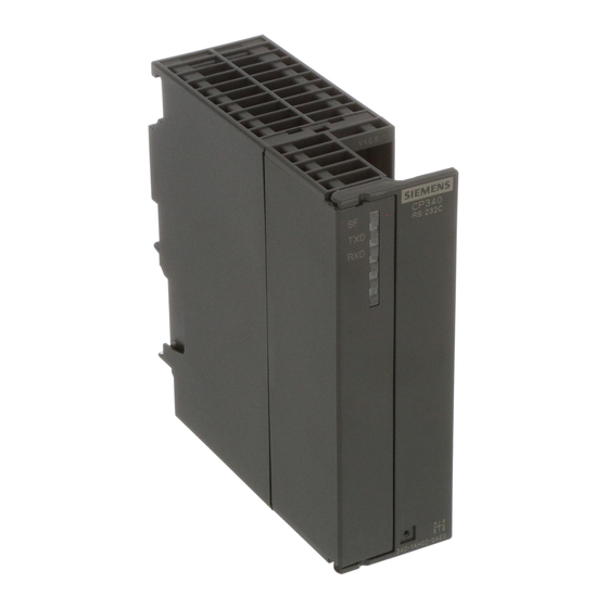
Page 16: Design Of The Cp 340
Product Description 1.3 Design of the CP 340 Design of the CP 340 Introduction The CP 340 communication processor is supplied with an integrated serial interface. Positions of module elements The figure shows the positions of the module elements on the front panel of the CP 340 communication processor. - Page 17 Product Description 1.3 Design of the CP 340 LED display elements The following LED display elements are located on the front panel of the communication processor: (red) Error display SF (green) Interface sending TxD (green) Interface receiving RxD Section "Diagnosis via the Display Elements of the CP 340 (Page 133)"...
-
Page 18: Properties Of The Serial Interface
Three module variants of the CP 340 are available, each having a different interface type that is suitable for different communication partners. For point-to-point connections between the CP 340 and a communication partner, Siemens offers standard connecting cables in various lengths. - Page 19 Product Description 1.4 Properties of the serial interface RS 232C signals The table below shows the meaning of the RS 232C accompanying signals. Table 1- 5 RS 232C interface signals Signal Designation Meaning Transmitted Data Transmitted data; transmission line is maintained at logic "1" by the communication processor in idle state.
-
Page 20: 20Ma-Tty Interface On The Cp 340-20Ma-Tty
Product Description 1.4 Properties of the serial interface 1.4.2 20mA–TTY interface on the CP 340–20mA-TTY Definition The 20mA-TTY interface is a current-loop interface used for serial data transmission. Features The 20mA-TTY interface has the following features and meets the following requirements: Type: Current-loop interface Front connector:... -
Page 21: X27 (Rs 422/485) Interface Of The Cp 340-Rs 422/485
Product Description 1.4 Properties of the serial interface 1.4.3 X27 (RS 422/485) Interface of the CP 340–RS 422/485 Definition The X27 (RS 422/485) interface is a voltage-difference interface for serial data transmission in compliance with the X27 standard. Properties The X27 (RS 422/485) interface has the following properties and fulfills the following requirements: Type: Differential voltage interface... - Page 22 Product Description 1.4 Properties of the serial interface PtP coupling and configuration of CP 340 Manual, 04/2011, A5E00369892-03...
-
Page 23: Basic Principles Of Serial Data Transmission
Basic Principles of Serial Data Transmission Serial Transmission of a Character Introduction The system provides various networking options for the exchange of data between two or more communication partners. The simplest form of data interchange is via a point-to-point connection between two communication partners. Point-to-point communication In point-to-point communication the communications processor forms the interface between a programmable controller and a communication partner. -
Page 24: Ptp Coupling And Configuration Of Cp
Basic Principles of Serial Data Transmission 2.1 Serial Transmission of a Character Bidirectional Data Traffic - Operating Modes The CP 340 has two operating modes for bidirectional data traffic: ● Half-duplex operation (3964(R) procedure, ASCII driver) Data are exchanged between the communication partners, but only in one direction at a time. - Page 25 Basic Principles of Serial Data Transmission 2.1 Serial Transmission of a Character Character frame Data is transmitted between the CP 340 and a communication partner via the serial interface in a 10-bit or 11-bit character frame. Three data formats are available for each character frame.
- Page 26 Basic Principles of Serial Data Transmission 2.1 Serial Transmission of a Character 11-Bit Character Frame The figure below shows the three possible data formats for an 11-bit character frame. 10 11 10 11 Figure 2-2 11-Bit Character Frame PtP coupling and configuration of CP 340 Manual, 04/2011, A5E00369892-03...
- Page 27 Basic Principles of Serial Data Transmission 2.1 Serial Transmission of a Character Character Delay Time The figure below shows the maximum time permitted between two characters received within a telegram. This is known as the character delay time. Figure 2-3 Character Delay Time PtP coupling and configuration of CP 340 Manual, 04/2011, A5E00369892-03...
-
Page 28: Transmission Mode In Point-To-Point Communication
Basic Principles of Serial Data Transmission 2.2 Transmission mode in Point-to-Point Communication Transmission mode in Point-to-Point Communication Introduction When data are transmitted, all communication partners must adhere to a fixed set of rules for handling and implementing data traffic. The ISO has defined a 7-layer model, which is recognized as the basis for a worldwide standardization of transmission protocols for computer-to-computer communication. - Page 29 Basic Principles of Serial Data Transmission 2.2 Transmission mode in Point-to-Point Communication ISO 7-Layer Reference Model The reference model defines the external behavior of the communication partners. Each protocol layer, except for the lowest one, is embedded in the next one down. The individual layers are as follows: 1.
-
Page 30: Transmission Integrity
Basic Principles of Serial Data Transmission 2.3 Transmission integrity Transmission integrity Introduction Transmission integrity plays an important role in the transmission of data and in selection of the transmission procedure. Generally speaking, the more layers of the reference model are applied, the greater the transmission integrity. - Page 31 Basic Principles of Serial Data Transmission 2.3 Transmission integrity Transmission Integrity with the ASCII Driver Data Integrity When Using the ASCII Driver: ● When data is transmitted via the ASCII driver, there are no data integrity precautions other than the use of a parity bit (can also be canceled, depending on how the character frame is set).
-
Page 32: Data Transmission With The 3964(R) Procedure
Basic Principles of Serial Data Transmission 2.4 Data Transmission with the 3964(R) Procedure Data Transmission with the 3964(R) Procedure Introduction The 3964(R) procedure control PtP data exchange between the communications processor and a communication partner. As well as the physical layer (layer 1), the 3964(R) procedure also incorporates the data-link layer (layer 2). -
Page 33: Block Checksum
Basic Principles of Serial Data Transmission 2.4 Data Transmission with the 3964(R) Procedure 2.4.2 Block Checksum Block Checksum With the 3964R transmission protocol, data integrity is increased by the additional sending of a block check character (BCC). Figure 2-5 Block Checksum The block checksum is the even longitudinal parity (EXOR operation on all data bytes) of a sent or received block. -
Page 34: Sending Data With 3964(R)
Basic Principles of Serial Data Transmission 2.4 Data Transmission with the 3964(R) Procedure 2.4.3 Sending Data with 3964(R) Process of Data Transmission when Sending The figure below illustrates the transmission sequence when data is sent with the 3964(R) procedure. Figure 2-6 Data Traffic when Sending with the 3964(R) Procedure Establishing a Send Connection To establish the connection, the 3964(R) procedure sends the control code STX. - Page 35 Basic Principles of Serial Data Transmission 2.4 Data Transmission with the 3964(R) Procedure Releasing a Send Connection If the communication partner sends the NAK control code during an active send operation, the procedure aborts its transmission of the block and tries again as described above. If a different code is sent, the procedure first waits for the character delay time to expire and then sends the NAK code to change the mode of the communication partner to idle.
- Page 36 Basic Principles of Serial Data Transmission 2.4 Data Transmission with the 3964(R) Procedure Sending with the 3964(R) procedure The figure below illustrates sending with the 3964(R) procedure. Sending with pro ced u re 3964(R ) S end request Send N A K W = 1 W >...
- Page 37 Basic Principles of Serial Data Transmission 2.4 Data Transmission with the 3964(R) Procedure C: Counter for connection attempts R: Counter for retries D: Default state W: Waiting for character reception PtP coupling and configuration of CP 340 Manual, 04/2011, A5E00369892-03...
-
Page 38: Receiving Data With 3964(R)
Basic Principles of Serial Data Transmission 2.4 Data Transmission with the 3964(R) Procedure 2.4.4 Receiving Data with 3964(R) Process of Data Transmission when Receiving The figure below illustrates the transmission sequence when data is received with the 3964(R) procedure. Figure 2-8 Data Traffic when Receiving with the 3964(R) Procedure Establishing a Receive Connection In idle mode, when there is no send request to be processed, the procedure waits for the... - Page 39 Basic Principles of Serial Data Transmission 2.4 Data Transmission with the 3964(R) Procedure Releasing a Receive Connection If transmission errors occur during receiving (lost character, frame error, parity error, etc.), the procedure continues to receive until the connection is shut down, then an NAK is sent to the communication partner.
- Page 40 Basic Principles of Serial Data Transmission 2.4 Data Transmission with the 3964(R) Procedure Receiving with the 3964(R) procedure The figure below illustrates receiving with the 3964(R) procedure. Receiving with procedure 3964(R) (part 1) Send request Character not equal to STX or faulty character S T X NAK or BREAK...
- Page 41 Basic Principles of Serial Data Transmission 2.4 Data Transmission with the 3964(R) Procedure Receiving with the 3964(R) procedure (part 2) The figure below illustrates receiving with the 3964(R) procedure. Receiving with procedure 3964(R) (part 2) Add character delay time Character DLE doubling received ? no errors, not...
- Page 42 Basic Principles of Serial Data Transmission 2.4 Data Transmission with the 3964(R) Procedure R: Counter for retries D: Default state W: Waiting for character reception PtP coupling and configuration of CP 340 Manual, 04/2011, A5E00369892-03...
-
Page 43: Handling Errored Data
Basic Principles of Serial Data Transmission 2.4 Data Transmission with the 3964(R) Procedure 2.4.5 Handling Errored Data Handling errored data The figure below illustrates how errored data is handled with the 3964(R) procedure. Figure 2-11 Data traffic when receiving errored data When DLE, ETX, BCC is received, the CP 340 compares the BCC of the communication partner with its own internally calculated value. - Page 44 Basic Principles of Serial Data Transmission 2.4 Data Transmission with the 3964(R) Procedure Initialization conflict The figure below illustrates the transmission sequence during an initialization conflict. Figure 2-12 Data traffic during an initialization conflict If a device responds to the communication partner's send request (code STX) within the acknowledgment delay time by sending the code STX instead of the acknowledgment DLE or NAK, an initialization conflict occurs.
- Page 45 Basic Principles of Serial Data Transmission 2.4 Data Transmission with the 3964(R) Procedure Procedure errors The procedure recognizes both errors caused by the communication partner and errors caused by faults on the line. In both cases, the procedure makes repeated attempts to send/receive the data block correctly.
-
Page 46: Data Transfer Using The Ascii Driver
Basic Principles of Serial Data Transmission 2.5 Data transfer using the ASCII driver Data transfer using the ASCII driver Introduction The ASCII driver controls data transmission via a point-to-point connection between the CP 340 and a communication partner. This driver contains the physical layer (layer 1). The structure of the message frames is left open through the S7 user passing on the complete send message frame to the CP 340. - Page 47 Basic Principles of Serial Data Transmission 2.5 Data transfer using the ASCII driver Using RS 232C accompanying signals The RS 232C accompanying signals can be used as follows: ● When automatic control of all RS 232C accompanying signals is configured ●...
- Page 48 Basic Principles of Serial Data Transmission 2.5 Data transfer using the ASCII driver ● Data can be received via the RS 232C interface as soon as the DSR line is set to ON. If the CP 340's receive buffer is close to overflow, the CP 340 will not respond. ●...
- Page 49 Basic Principles of Serial Data Transmission 2.5 Data transfer using the ASCII driver Data flow control/Handshaking Handshaking controls the data flow between two communication partners. Handshaking ensures that data is not lost in transmissions between devices that work at different speeds. There are essentially two types of handshaking: ●...
-
Page 50: Sending Data With The Ascii Driver
Basic Principles of Serial Data Transmission 2.5 Data transfer using the ASCII driver 2.5.2 Sending Data with the ASCII Driver Sending When sending data, specify the number of bytes of user data to be transmitted as the "LEN" parameter when you call the P_SEND function block. The user data must contain any required start-of-text and end-of-text characters. -
Page 51: Receiving Data With The Ascii Driver
Basic Principles of Serial Data Transmission 2.5 Data transfer using the ASCII driver 2.5.3 Receiving Data with the ASCII Driver Selectable End Criteria For data transmission using the ASCII driver you can choose between three different end criteria. The end criterion defines when a complete message frame is received. The possible end criteria are as follows: ●... - Page 52 Basic Principles of Serial Data Transmission 2.5 Data transfer using the ASCII driver End Criterion "Expiration of Character Delay Time" When data is received, the end of the message frame is recognized when the character delay time expires. The received data is taken over by the CPU with the function block P_RCV.
- Page 53 Basic Principles of Serial Data Transmission 2.5 Data transfer using the ASCII driver End Criterion End-of-Text Character When data is received, the end of the message frame is recognized when the configured end-of-text character(s) arrive. The received data, including the end-of-text character, is taken over by the CPU with the function block P_RCV.
- Page 54 Basic Principles of Serial Data Transmission 2.5 Data transfer using the ASCII driver End Criterion Fixed Message Frame Length When data is received, the end of the message frame is recognized when the configured number of characters has arrived. The received data is taken over by the CPU with the function block P_RCV.
-
Page 55: Break - Monitoring On Cp 340
Basic Principles of Serial Data Transmission 2.5 Data transfer using the ASCII driver 2.5.4 BREAK - Monitoring on CP 340 BREAK evaluation A BREAK evaluation occurs only if the BREAK monitoring is not deactivated with the parameter assignment user interface. 2.5.5 Receive Buffer on CP 340 Receive buffer on CP 340... -
Page 56: Data Transmission With The Printer Driver
Basic Principles of Serial Data Transmission 2.6 Data transmission with the printer driver Data transmission with the printer driver Introduction The printer driver allows you to output date- and time-stamped message texts to a printer. This enables you to monitor simple processes, print error or fault messages or issue instructions to operating personnel, for example. - Page 57 Basic Principles of Serial Data Transmission 2.6 Data transmission with the printer driver Variables Up to 4 variables (3 + a message text number) can be displayed in a message text. The values of variables can be transmitted from the CPU to the CP 340. The following can be displayed as variables: Calculated values of the user program, such as: levels), date and time, strings (string variables), or other message texts.
- Page 58 Basic Principles of Serial Data Transmission 2.6 Data transmission with the printer driver Examples Example 1: The level "200" l was reached at "17:30" hours. Format string = The level %i l was reached at %Z hours. Variable 1 = time Variable 2 = level Example 2: The pressure in the chamber "is falling"...
- Page 59 Basic Principles of Serial Data Transmission 2.6 Data transmission with the printer driver Outputting a message text The figure below illustrates the sequence of operations for a printout. Figure 2-18 Flow chart of printout Data flow control/Handshaking Handshaking controls the data flow between two communication partners. Handshaking ensures that data is not lost in transmissions between devices that work at different speeds.
- Page 60 Basic Principles of Serial Data Transmission 2.6 Data transmission with the printer driver BUSY signal The CP 340 evaluates the printer's "BUSY" control signal. The printer indicates to the CP 340 that it is ready to receive: ● CP 340-20mA-TTY: current on RxD line ●...
-
Page 61: Parameterization Data
Basic Principles of Serial Data Transmission 2.7 Parameterization Data Parameterization Data Introduction By setting the basic parameter, you can define the diagnosis behavior of the CP 340. By selecting different protocols, you can adjust your CP 340 communications processor to suit the properties of the communication partner. -
Page 62: Parameterization Data Of The 3964(R) Procedure
Basic Principles of Serial Data Transmission 2.7 Parameterization Data 2.7.2 Parameterization Data of the 3964(R) Procedure Introduction Using the parameter assignment data of the 3964(R) procedure, you can adjust the CP 340 to suit the properties of its communication partner. Parameter assignment data of the 3964(R) procedure With the CP 340: Point-to-Point Communication, Parameter Assignment user interface, you can specify the parameters for the physical layer (layer 1) and for the data connection layer... - Page 63 Basic Principles of Serial Data Transmission 2.7 Parameterization Data Protocol The table below describes the protocol. Table 2- 2 3964(R) protocol Parameter Description Default value 3964 with default values and no block 3964R with default values and block Default values are assigned to the ...
- Page 64 Basic Principles of Serial Data Transmission 2.7 Parameterization Data Protocol parameters You can only set the protocol parameters if you have not set the default values in the protocol. Table 2- 3 Protocol parameters (3964(R) procedure) Parameter Description Range of values Default value Character delay time The character delay time defines the...
- Page 65 Basic Principles of Serial Data Transmission 2.7 Parameterization Data Parameter Description Range of values Default value Parity A sequence of information bits can be extended None Even to include another bit, the parity bit. The addition of its value ("0" or "1") brings the value of all the Even ...
-
Page 66: Parameterization Data Of The Ascii Driver
Basic Principles of Serial Data Transmission 2.7 Parameterization Data 2.7.3 Parameterization data of the ASCII driver Introduction Using the parameter assignment data of the ASCII driver, you can adjust the communication processor to suit the properties of its communication partner. Parameter assignment data of the ASCII driver With the CP 340: Point-to-Point Communication, Parameter Assignment interface, specify the parameters for the physical layer (layer 1) of the ASCII driver. - Page 67 Basic Principles of Serial Data Transmission 2.7 Parameterization Data Protocol parameters The table below describes the protocol parameters. Table 2- 6 Protocol parameters (ASCII driver) Parameter Description Range of values Default value Indicator for end of received Defines which criterion After character delay time After character delay time ...
- Page 68 Basic Principles of Serial Data Transmission 2.7 Parameterization Data Baud rate/Character frame The table below contains descriptions of and specifies ranges of values for the relevant parameters. Table 2- 7 Baud rate/Character frame (ASCII driver) Parameter Description Range of values Default value Baud rate Data transmission rate in bps.
- Page 69 Basic Principles of Serial Data Transmission 2.7 Parameterization Data Data flow control The table below contains a description of the parameters for data flow control. Data flow control is not possible with the RS 485 interface. Flow control with "RTS/CTS" and "automatic control of V24 signals"...
- Page 70 Basic Principles of Serial Data Transmission 2.7 Parameterization Data Receive buffer on CP The table below describes the parameters for the CP receive buffer. Table 2- 9 Receive buffer on CP (ASCII driver) Parameter Description Range of values Default value Delete CP receive buffer on You can specify whether the CP receive ...
- Page 71 Basic Principles of Serial Data Transmission 2.7 Parameterization Data X27 (RS 422/485) interface You will find a description of the parameters for the X27 (RS 422/485) interface in the table below. Table 2- 10 X27 (RS 422/485) interface (ASCII driver) Parameter Description Range of values...
-
Page 72: Parameterization Data Of The Printer Driver
Basic Principles of Serial Data Transmission 2.7 Parameterization Data 2.7.4 Parameterization data of the printer driver Introduction You can use the parameter assignment data of the printer driver to generate the transmission-specific parameters and the message texts for printout. Parameter assignment data of the printer driver With the CP 340: Point-to-Point Communication, Parameter Assignment user interface, you can specify: ●... - Page 73 Basic Principles of Serial Data Transmission 2.7 Parameterization Data Parameter Description Range of values Default value Activate You can choose whether monitoring for an Depending on the HW variant BREAK interrupted receive line should be activated or used and the operating mode ...
- Page 74 Basic Principles of Serial Data Transmission 2.7 Parameterization Data X27 (RS 422/485) interface You will find a description of the parameters for the X27 (RS 422/485) interface in the table below. Table 2- 13 X27 (RS 422/485) interface (ASCII driver) Parameter Description Range of values...
- Page 75 Basic Principles of Serial Data Transmission 2.7 Parameterization Data Parameter Description Range of values Default value Separators/ Characters which end each CR LF (carriage return and CR (carriage return) line in the body of the text, line feed) Line end LF (line feed) ...
- Page 76 Basic Principles of Serial Data Transmission 2.7 Parameterization Data Features Conditions for configuring message texts: ● Size of the text SDB: 8 KB ● Max. length of a message text without variables: 150 characters ● Max. length of a message text with variables displayed: 250 characters ●...
-
Page 77: Conversion And Control Statements For Printer Output
Basic Principles of Serial Data Transmission 2.7 Parameterization Data 2.7.5 Conversion and Control Statements for Printer Output Introduction The output of a message text with variables and control instructions (e.g., for bold, condensed, expanded, or italic type and underlining) is defined by means of a format string. In the format string you can also define statements to execute other useful functions for printout (e.g., to set a page number or start a new page). - Page 78 Basic Principles of Serial Data Transmission 2.7 Parameterization Data Conversion statement The figure illustrates the structure of a conversion statement schematically. Figure 2-21 Schematic structure of a conversion statement Flag Without = Right-justified output – Left-justified output Width Withou Output in the standard representation Exactly n characters are output (up to 255 characters are possible);...
-
Page 79: Display Type
Basic Principles of Serial Data Transmission 2.7 Parameterization Data Display type The table below describes the possible display types for the values of the variables. Display types N and P are exceptions and are explained below the table. The display type supports both uppercase and lowercase letters. Table 2- 18 Display types in the conversion statement Display type... - Page 80 Basic Principles of Serial Data Transmission 2.7 Parameterization Data Display type Associated data type Default display Width of the default Description display DATE_AND_TIME_ 10.06.1992 Date and time of day OF_DAY, DT –15:42:59.723 TIME_OF_DAY 15:42:59.723 Time of day DWORD If there is no message text number or system time in these display types, 6 * characters appear in the printout instead (the CP 340 does not keep the time).
- Page 81 Basic Principles of Serial Data Transmission 2.7 Parameterization Data Setting the page number (%P) Use the P display type to change the page number in the printout. The CP 340 always begins a printout at page 1. This conversion statement allows you to set the page number to a specific value.
- Page 82 Basic Principles of Serial Data Transmission 2.7 Parameterization Data ● You must use control instructions to specify formatting (line feed, tabs, etc.) in a message text or in the printout of a long conversion statement. ● If both the format string and the message text contain conversion statements, the format string is expanded first, followed by the message text.
- Page 83 Basic Principles of Serial Data Transmission 2.7 Parameterization Data Examples of correct conversion statements Below are some examples of correct conversion statements. Example 1: ..31.10.1996 Format string = %15.4A Variable 1 = D#1996–10–31 A width of 15 with a precision of 4 (width of the year) and right-justified formatting were selected.
- Page 84 Basic Principles of Serial Data Transmission 2.7 Parameterization Data Control instructions Control instructions are used to achieve specific results in the printout (e.g., underlining). In addition to the standard control instructions (for bold, condensed, expanded, or italic type and underlining), you can also use other control characters if you enter them in the control character table on the CP 340: Point-to-Point Communication, Parameter Assignment user interface before parameterizing the CP 340.
- Page 85 Basic Principles of Serial Data Transmission 2.7 Parameterization Data Starting a new page (\F) Taking into account the assigned page layout, i.e. the configured headers and footers and the number of lines per page, the \F control instruction can be used to begin a new page. This differs from a pure form feed on the printer.
- Page 86 Basic Principles of Serial Data Transmission 2.7 Parameterization Data PtP coupling and configuration of CP 340 Manual, 04/2011, A5E00369892-03...
-
Page 87: Starting Up The Cp 340
Starting up the CP 340 Step sequence Before commissioning the CP 340 you will need to perform the following operations in the order given. 1. Install the communication processor 2. Configure the communication processor 3. Assign the communication processor parameters 4. - Page 88 Starting up the CP 340 Backing up parameterization data A backup of CP parameterization data includes the storage of parameters, their download to the CPU and transfer to the CP. Back up your parameterization data using STEP 7 software. You can find a detailed description in Section "Managing the Parameter Data (Page 97)" of the manual.
-
Page 89: Mounting The Cp 340
Mounting the CP 340 CP 340 slots Introduction The following section describes the rules you must observe when positioning the CP 340 in the rack. Positioning of the CP 340 in the Rack The following rules apply when positioning the CP 340 in the rack: ●... -
Page 90: Installing And Removing The Cp 340
Mounting the CP 340 4.2 Installing and removing the CP 340 Installing and removing the CP 340 Introduction When mounting and dismounting the CP 340, you must observe certain rules. Tool For mounting and dismounting the CP 340 you require a 4.5 mm cylindrical screwdriver. Note Before you mount or dismount the CP 340, you must switch the CPU to STOP mode. -
Page 91: Removal Steps
Mounting the CP 340 4.2 Installing and removing the CP 340 4.2.2 Removal steps To remove the CP 340 To dismount the CP 340 from the rack, proceed as follows: 1. Switch the CPU to STOP mode. 2. Open the front panel doors. 3. - Page 92 Mounting the CP 340 4.2 Installing and removing the CP 340 PtP coupling and configuration of CP 340 Manual, 04/2011, A5E00369892-03...
-
Page 93: Configuring And Parameterizing The Cp 340
Configuring and Parameterizing the CP 340 Parameterization Options Configuration options You configure and parameterize the module variants of the CP 340 using STEP 7 or the CP 340: Point-to-Point Communication, Parameter Assignment user interface. Table 5- 1 Configuration options for the CP 340 Product Order number Configurable using the... -
Page 94: Parameterizing The Communications Protocols
Configuring and Parameterizing the CP 340 5.2 Parameterizing the Communications Protocols Parameterizing the Communications Protocols Introduction Once you have entered the CP 340 in the configuration table, you must supply its interface with parameters. In the case of the printer driver, you can also configure message texts for printer output. -
Page 95: Installing The Engineering Tool
Configuring and Parameterizing the CP 340 5.2 Parameterizing the Communications Protocols 5.2.2 Installing the engineering tool Installation The CP 340: Point-to-Point Communication, Parameter Assignment parameter assignment interface is located on a data carrier along with the function blocks and programming example. -
Page 96: Configuring The Cp 340
Configuring and Parameterizing the CP 340 5.3 Configuring the CP 340 Configuring the CP 340 Introduction Once you have mounted the CP 340 you must inform the programmable controller that it is there. This process is known as "configuration". Prerequisite Before you can enter the CP 340 in the configuration table of the STEP 7 software, you must have created a project and a terminal with STEP 7. -
Page 97: Managing The Parameter Data
Configuring and Parameterizing the CP 340 5.4 Managing the Parameter Data Managing the Parameter Data Introduction The configuration and parameterization data of the communication processor is stored in the current project (on the hard disk of the programming device/PC). Data management When you quit the configuration table by selecting the menu command Station >... -
Page 98: Identification Data
Configuring and Parameterizing the CP 340 5.5 Identification data Identification data Definition Identification data represent information stored on the module and support you in: ● Troubleshooting a plant ● Verifying your plant configuration ● Locating hardware modifications in a plant This ID data allows the unambiguous identification of modules in online mode. - Page 99 Index 1 (data record 231/read only) Manufacturer Read 00 2A hex (= 42 dec) The name of the manufacturer is saved to this (2 bytes) parameter (42 dec = Siemens AG). Device name Read 6ES7 340–1xH02–0AE0 Order number of the module (20 bytes)
-
Page 100: Download Of Firmware Updates
Switch the CPU to STOP before you download the module firmware file for the CP 340. Update not completed successfully The module's red SF LED flashes if the update was not successful. Repeat the update. Contact your local Siemens representative if the update fails. PtP coupling and configuration of CP 340 Manual, 04/2011, A5E00369892-03... - Page 101 Configuring and Parameterizing the CP 340 5.6 Download of firmware updates LED display elements LED display elements when the FW update operation is active: Table 5- 5 LED display elements during the FW update Status Remark To correct or avoid errors FW update in progress...
- Page 102 Configuring and Parameterizing the CP 340 5.6 Download of firmware updates PtP coupling and configuration of CP 340 Manual, 04/2011, A5E00369892-03...
-
Page 103: Communication Using Function Blocks
Communication using function blocks Communication via Function Blocks Introduction Communication between the CPU, the CP 340 and a communication partner takes place via the function blocks and the protocols of the CP 340. Communication between CPU and CP 340 The function blocks form the software interface between the CPU and the CP 340. They must be called up cyclically from the user program. -
Page 104: Overview Of The Function Blocks
Communication using function blocks 6.2 Overview of the Function Blocks Overview of the Function Blocks Introduction The S7-300 programmable controller provides you with a number of function blocks which initiate and control communication between the CPU and the CP 340 communications processor in the user program. -
Page 105: Using The Function Blocks For Connecting To A Communications Processor
Communication using function blocks 6.3 Using the function blocks for connecting to a communications processor Using the function blocks for connecting to a communications processor Introduction The following function blocks are available for linking with a communication partner: P_SEND (FB 3) for sending data, and P_PRCV (FB 2) for receiving data in the cyclical program. - Page 106 Communication using function blocks 6.3 Using the function blocks for connecting to a communications processor The DONE output shows "job completed without errors". ERROR indicates whether an error has occurred. If an error has occurred, the corresponding event number is displayed in STATUS (see Chapter "Diagnostics Messages of the Function Blocks P_SEND, P_RCV and P_PRINT (Page 134)").
- Page 107 Communication using function blocks 6.3 Using the function blocks for connecting to a communications processor Assignment in the data area The P_SEND function block works together with an Instance DB for I_SEND. The DB number is specified in the call. The instance data block is 40 bytes long. Access to the data in the instance DB is not permitted.
- Page 108 Communication using function blocks 6.3 Using the function blocks for connecting to a communications processor Time Sequence Chart for P_SEND (FB 3) The figure below illustrates the behavior of the DONE and ERROR parameters, depending on how the REQ and R inputs are wired. Figure 6-1 Time Sequence Chart for P_SEND (FB 3) Note...
-
Page 109: S7 Receives Data From A Communication Partner
Communication using function blocks 6.3 Using the function blocks for connecting to a communications processor 6.3.2 S7 receives data from a communication partner receiving data The P_RCV FB transmits data from the CP 340 to an S7 data area specified by the parameters DB_NO, DBB_NO and LEN. - Page 110 Communication using function blocks 6.3 Using the function blocks for connecting to a communications processor Block call STL representation LAD representation CALL P_RCV, I_RCV EN_R : = R : = LADDR: = DB_NO: = DBB_NO: = NDR : = ERROR: = LEN: = STATUS: = Note...
- Page 111 Communication using function blocks 6.3 Using the function blocks for connecting to a communications processor P_RCV (FB 2) parameters The table below lists the parameters of P_RCV (FB 2). Table 6- 3 P_RCV (FB 2) parameters Name Type Data type Comment Permitted values, comment EN_R...
- Page 112 Communication using function blocks 6.3 Using the function blocks for connecting to a communications processor Time Sequence Chart for FB 2 P_RCV The figure below illustrates the behavior of the parameters NDR, LEN and ERROR, depending on how the EN_R and R inputs are wired. Figure 6-2 Time Sequence Chart FB_2_P_RCV Note...
-
Page 113: Using Function Blocks For The Output Of Message Texts To A Printer
Communication using function blocks 6.4 Using function blocks for the output of message texts to a printer Using function blocks for the output of message texts to a printer Introduction The P_PRINT function block (FB 4) is available to you for outputting message texts to a printer. - Page 114 Communication using function blocks 6.4 Using function blocks for the output of message texts to a printer The DONE output shows "job completed without errors". ERROR indicates whether an error has occurred. If an error has occurred, the corresponding event number is displayed in STATUS (see Chapter "Diagnostics Messages of the Function Blocks P_SEND, P_RCV and P_PRINT (Page 134)").
- Page 115 Communication using function blocks 6.4 Using function blocks for the output of message texts to a printer Assignment in the data area, instance DB The P_PRINT function block works together with an I_PRINT instance DB. The DB number is specified in the call. The instance data block is 40 bytes long. Access to the data in the instance DB is not permitted.
- Page 116 Communication using function blocks 6.4 Using function blocks for the output of message texts to a printer Permissible DB Number The permissible DB numbers are CPU-specific. If the value 16#00 is specified as the DB number for "Pointer to variable", this variable is interpreted as not present and the pointer is set to the next variable or the format string.
- Page 117 Communication using function blocks 6.4 Using function blocks for the output of message texts to a printer Time Sequence Chart for FB 4 P_PRINT The figure below illustrates the behavior of the DONE and ERROR parameters, depending on how the REQ and R inputs are wired. Figure 6-4 Time Sequence Chart for FB 4 P_PRINT Note...
-
Page 118: Use Of Function Blocks For Reading And Controlling The Rs 2332C Secondary Signals
Communication using function blocks 6.5 Use of function blocks for reading and controlling the RS 2332C secondary signals Use of function blocks for reading and controlling the RS 2332C secondary signals Introduction The functions available for reading and controlling the RS 232C secondary signals are V24_STAT (FC 5) for checking the interface statuses and V24_SET (FC 6) for setting/resetting the interface outputs. - Page 119 Communication using function blocks 6.5 Use of function blocks for reading and controlling the RS 2332C secondary signals Note The EN and ENO parameters are only present in the graphical representation (LAD or FBD). To process these parameters, the compiler uses the binary result. The binary result is set to signal state "1"...
- Page 120 Communication using function blocks 6.5 Use of function blocks for reading and controlling the RS 2332C secondary signals Setting/resetting interface outputs of the CP 340 The user can set or reset the interface outputs via the corresponding parameter inputs of the V24_SET FC.
-
Page 121: Delete Receive Buffer, Fb12 "P_Reset
Communication using function blocks 6.6 Delete receive buffer, FB12 "P_RESET" Delete receive buffer, FB12 "P_RESET" P_RESET FB The P_RESET FB deletes the entire receive buffer of the CP 340. All saved frames will be discarded. Any frame that is incoming at the time when the P_RESET FB is called will be saved. - Page 122 Communication using function blocks 6.6 Delete receive buffer, FB12 "P_RESET" Assignment in the data area The P_RESET function block works together with an I_P_RESET instance DB. The DB number is specified in the call. The data in the instance DB cannot be accessed. Note Exception: In the event of an error, STATUS == W#16#1E0F, you will find more detailed information in the SFCERR or SFCSTATUS variables.
- Page 123 Communication using function blocks 6.6 Delete receive buffer, FB12 "P_RESET" Time sequence chart for the P_RESET FB The figure below illustrates the behavior of the DONE and ERROR parameters depending on the input circuit of REQ. Figure 6-5 Time sequence chart for the P_RESET FB Note The REQ input is edge-triggered.
-
Page 124: General Information On Program Processing
Communication using function blocks 6.7 General Information on Program Processing General Information on Program Processing Start-up Behavior of CP 340 Programmable Controller The parameterization data are generated using CP 340: Point-to-Point Communication, Parameter Assignment parameterization interface and transmitted to the CPU with the STEP 7 software. -
Page 125: Technical Data Of The Function Blocks
Communication using function blocks 6.8 Technical data of the function blocks Technical data of the function blocks Introduction Listed below is the technical specifications relating to memory requirements, runtimes, minimum number of CPU cycles, and system functions used. Memory requirements The table below lists the memory requirements of the CP 340 function blocks/functions. - Page 126 Communication using function blocks 6.8 Technical data of the function blocks System functions used The following system functions are used in the blocks: ● SFB 52 (RDREC), Read data set ● SFB 53 (WRREC), Write data set Notice The new standard function blocks of the CP340 ●...
-
Page 127: Startup
Startup Operating Modes of the CP 340 Introduction The CP 340 has the operating modes STOP, new parameterization and RUN. STOP When the CP 340 is in STOP mode, no protocol driver is active and all send and receive jobs from the CPU are given a negative acknowledgment. The CP 340 remains in STOP mode until the cause of the stop is removed (e.g., break, invalid parameter). -
Page 128: Startup Characteristics Of The Cp 340
Startup 7.2 Startup Characteristics of the CP 340 Startup Characteristics of the CP 340 Introduction The CP 340 start-up is divided into two phases: ● Initialization (CP 340 in POWER ON mode) ● Parameterization Initialization As soon as the CP 340 is connected to the power supply, the serial interface is supplied with default parameters (the interface parameters are given preset values at the factory) of the module. -
Page 129: Behavior Of The Cp 340 On Operating Mode Transitions Of The Cpu
Startup 7.3 Behavior of the CP 340 on Operating Mode Transitions of the CPU Behavior of the CP 340 on Operating Mode Transitions of the CPU Introduction Once the CP 340 has been started up, all data is exchanged between the CPU and the CP 340 by means of the function blocks. - Page 130 Startup 7.3 Behavior of the CP 340 on Operating Mode Transitions of the CPU Points to Note when Receiving Message Frames With the CP 340: Point–to–Point Communication, Parameter Assignment tool can be used to configure the “Delete CP receive buffer at startup = yes/no.” ●...
-
Page 131: Diagnostics With The Cp 340
Diagnostics with the CP 340 Introduction The diagnostics functions of the CP 340 enable you to quickly localize any errors which occur. The following diagnostics options are available: ● Diagnosis via the Display Elements of the CP 340 ● Diagnosis via the STATUS output of the function blocks ●... - Page 132 Diagnostics with the CP 340 Diagnostic Buffer of the CP 340 All the CP 340's errors are entered in its diagnostic buffer. In the same way as with the diagnostic buffer of the CPU, you can also use the STEP 7 information functions on the programming device to display the user-relevant information of the CP diagnostic buffer (see Chapter "Diagnostics by means of the diagnostic buffer of the CP 340 (Page 144)").
-
Page 133: Diagnosis Via The Display Elements Of The Cp 340
Diagnostics with the CP 340 8.1 Diagnosis via the Display Elements of the CP 340 Diagnosis via the Display Elements of the CP 340 Introduction The display elements of the CP 340 provide information on the CP 340. The following display functions are distinguished: ●... -
Page 134: Diagnostics Messages Of The Function Blocks P_Send, P_Rcv And P_Print
Diagnostics with the CP 340 8.2 Diagnostics Messages of the Function Blocks P_SEND, P_RCV and P_PRINT Diagnostics Messages of the Function Blocks P_SEND, P_RCV and P_PRINT Introduction Every function block has a STATUS parameter for error diagnostics. The STATUS message numbers always have the same meaning, irrespective of which function block is used. - Page 135 Diagnostics with the CP 340 8.2 Diagnostics Messages of the Function Blocks P_SEND, P_RCV and P_PRINT Event classes The table below describes the various event classes and numbers. Table 8- 1 Event classes and event numbers Event class 5 (05H): "Error while processing CPU request"...
- Page 136 Diagnostics with the CP 340 8.2 Diagnostics Messages of the Function Blocks P_SEND, P_RCV and P_PRINT Event class 5 (05H): "Error while processing CPU request" Event no. Event To correct or avoid errors (05)1BH Only for printer drivers: Correct the specified precision in the conversion statement.
- Page 137 Diagnostics with the CP 340 8.2 Diagnostics Messages of the Function Blocks P_SEND, P_RCV and P_PRINT Event class 7 (07H): "Send error" Event no. Event To correct or avoid errors (07)05H Only for 3964(R): Check whether the partner is also indicating errors, possibly because not all transmitted data arrived Negative acknowledgment when sending (e.g., break in the transmission line), fatal errors are...
- Page 138 Diagnostics with the CP 340 8.2 Diagnostics Messages of the Function Blocks P_SEND, P_RCV and P_PRINT Event class 8 (08H): "Receive error" Event no. Event To correct or avoid errors (08)01H Only for 3964(R): A repetition is not an error, but it can indicate that there is interference on the data link or the partner Expectation of the first repetition: device has malfunctioned.
- Page 139 Diagnostics with the CP 340 8.2 Diagnostics Messages of the Function Blocks P_SEND, P_RCV and P_PRINT Event class 8 (08H): "Receive error" Event no. Event To correct or avoid errors (08)0AH There is no free receive buffer available: The P_RCV FB must be called more frequently. No receive buffer space available for receiving data.
- Page 140 Diagnostics with the CP 340 8.2 Diagnostics Messages of the Function Blocks P_SEND, P_RCV and P_PRINT Displaying and evaluating the STATUS output You can display and evaluate the actual address of the function blocks' STATUS outputs. Note An error message is only output if the ERROR bit (job completed with error) is set at the same time.
- Page 141 Diagnostics with the CP 340 8.2 Diagnostics Messages of the Function Blocks P_SEND, P_RCV and P_PRINT Calling the SFCERR or SFCSTATUS variable You can call the SFCERR or SFCSTATUS variable to obtain more detailed information about the pending event class 30 error, 14 (1E0EH) or 15 (1E0FH). You can only load the SFCERR or SFCSTATUS variable by means of symbolic access to the corresponding function block's instance DB.
-
Page 142: Diagnostics Via The S7-300 Backplane Bus
Diagnostics with the CP 340 8.3 Diagnostics via the S7-300 backplane bus Diagnostics via the S7-300 backplane bus Introduction The CP 340 can trigger a diagnostics alarm on the assigned CPU, thus indicating a malfunction of the CP 340. You can specify at parameterization whether the CP 340 is to trigger a diagnostics alarm or not in the event of serious errors (see Chapter "Basic parameters of the CP 340 (Page 61)"). - Page 143 Diagnostics with the CP 340 8.3 Diagnostics via the S7-300 backplane bus 1st, 3rd and 4th bytes: The 1st, 3rd, and 4th bytes of the diagnostic data represent the error that has occurred. Bit 0 in the 1st byte is the group error display (SF). Bit 0 is always set to "1" if at least one bit from bits 1 to 7 is set to "1", i.e.
-
Page 144: Diagnostics By Means Of The Diagnostic Buffer Of The Cp 340
Diagnostics with the CP 340 8.4 Diagnostics by means of the diagnostic buffer of the CP 340 Diagnostics by means of the diagnostic buffer of the CP 340 Diagnostic buffer on the CP 340 The CP 340 has its own diagnostic buffer, in which all the diagnostic events of the CP 340 are entered in the sequence in which they occur. -
Page 145: Ptp Coupling And Configuration Of Cp
Diagnostics with the CP 340 8.4 Diagnostics by means of the diagnostic buffer of the CP 340 Proceed as follows: 1. Open the SIMATIC 300 station concerned (double-click or select menu command Edit > Open). 2. Then open the "Hardware" object (also by double-clicking or selecting menu command Edit >... - Page 146 Diagnostics with the CP 340 8.4 Diagnostics by means of the diagnostic buffer of the CP 340 PtP coupling and configuration of CP 340 Manual, 04/2011, A5E00369892-03...
-
Page 147: Programming Example For Standard Function Blocks
Programming Example for Standard Function Blocks Introduction The programming example given here describes standard functions for operating the CP 340 communications processor. Objective The programming example ● aims to show examples of the most important functions ● enables the correct functioning of the connected hardware to be checked (and is therefore simple and easy to follow) ●... -
Page 148: Device Configuration
Programming Example for Standard Function Blocks 9.1 Device Configuration Device Configuration Application To try out the sample program, you could use the following devices: ● One S7-300 programmable controller (mounting rack, power supply, CPU) ● One CP 340 module with a communications partner (e.g. a second CP) or printer, or you could plug in a "short-circuit connector", i.e. -
Page 149: Settings
Programming Example for Standard Function Blocks 9.2 Settings Settings Settings in the CPU via STEP 7 You must configure your controller setup with STEP 7: ● Slot 1: Power supply ● Slot 2: CPU ● Slot 4: Digital input, IB0 and IB1 ●... -
Page 150: Blocks Used
Programming Example for Standard Function Blocks 9.3 Blocks Used Blocks Used Blocks Used The table below shows the blocks used for the sample program. Block Symbol Description OB 1 CYCLE Cyclic program processing OB 100 RESTART Restart processing DB 2 DB_P_RCV Instance DB for P_RCV FB DB 3... -
Page 151: Example "Point-To-Point Communication
Programming Example for Standard Function Blocks 9.4 Example “Point–to–Point Communication” Example “Point–to–Point Communication” Introduction The inputs and outputs are mapped to memory bits at the beginning and end of OB 1. Only the memory bits are used in the test program. Inputs and outputs used for FB 2 and FB 3 The table below shows the assignment of the inputs/outputs and memory bits. - Page 152 Programming Example for Standard Function Blocks 9.4 Example “Point–to–Point Communication” Symbol Input/output Flag Comment Q 5.6 M 9.6 "0" Q 5.7 M 9.7 "0" Input/Output parameters for FB 2 and FB 3 The table below shows how the input/output parameters of FB 2 and FB 3 are mapped to bit memories.
-
Page 153: 9.5 Example "Printing" And "Reading And Controlling The Cp 340 Inputs/Outputs
Programming Example for Standard Function Blocks 9.5 Example "Printing" and "Reading and Controlling the CP 340 Inputs/Outputs" Example "Printing" and "Reading and Controlling the CP 340 Inputs/Outputs" Introduction The inputs and outputs are mapped to memory bits at the beginning and end of OB 1. Only the memory bits are used in the test program. - Page 154 Programming Example for Standard Function Blocks 9.5 Example "Printing" and "Reading and Controlling the CP 340 Inputs/Outputs" Symbol Input/output Flag Comment A_V24_STAT_RI_IN Q 5.5 M 9.5 STAT_RI_IN Q 5.6 M 9.6 "0" Q 5.7 M 9.7 "0" Input/Output parameters for FC 5 and FC 6 The table below shows how the input/output parameters of FC 5 and FC 6 are mapped to bit memories.
-
Page 155: Installation, Error Messages
Programming Example for Standard Function Blocks 9.6 Installation, Error Messages Installation, Error Messages Scope of Supply and Installation The program example of the CP 340, the CP 340: Point–to–Point Communication, Parameter Assignment and the function blocks are available on a data carrier that is included with this manual. -
Page 156: Activation, Start-Up Program And Cyclic Program
Programming Example for Standard Function Blocks 9.7 Activation, Start-Up Program and Cyclic Program Activation, Start-Up Program and Cyclic Program Activation, startup program The startup program is located in OB 100. At startup, only the logical base address of the CP 340 is entered in the MW BGADR (MW 21). - Page 157 Programming Example for Standard Function Blocks 9.7 Activation, Start-Up Program and Cyclic Program Description of "reading and controlling the CP 340 inputs/outputs" The "read and control RS 232C accompanying signals" functions can only be carried out with the ASCII driver. A prerequisite is that you have not set the “Automat. control of V24 signals"...
- Page 158 At 23:32:16.816 hours: Level exceeds upper limit At 23:32:21.681 hours: Level falls below upper limit The level 200 l was reached at 23:32:26.988 hours Copyright © Siemens AG 1996. All rights reserved PtP coupling and configuration of CP 340 Manual, 04/2011, A5E00369892-03...
-
Page 159: Technical Specifications
Technical Specifications Technical Specifications of the CP 340 General technical specifications The table below lists the general technical specifications for the CP 340. For additional technical specifications of the SIMATIC S7-300, see Chapter 1 "General S7-300 Automation Systems, Module Data technical specifications"... - Page 160 Technical Specifications A.1 Technical Specifications of the CP 340 Technical specifications for the RS 232C interface The table below shows the technical specifications for the RS 232C interface of CP 340-RS 232C. Table A- 2 Technical specifications for the RS 232C interface RS 232C interface Interface RS 232C,...
- Page 161 Technical Specifications A.1 Technical Specifications of the CP 340 Technical specifications for the 3964(R) procedure The table below shows the technical specifications for the 3964(R) procedure. Table A- 5 Technical specifications for the 3964(R) procedure 3964(R) procedure with default values Max.
- Page 162 Technical Specifications A.1 Technical Specifications of the CP 340 Technical specifications for the ASCII driver The table below shows the technical specifications for the ASCII driver. Table A- 6 Technical specifications for the ASCII driver ASCII driver Max. message frame 1024 bytes length Parameter...
- Page 163 Technical Specifications A.1 Technical Specifications of the CP 340 Technical specifications for the printer driver The table below shows the technical specifications for the printer driver. Table A- 7 Technical specifications for the printer driver Printer driver Length of the text SDB 8 KB Parameter The following can be configured:...
-
Page 164: Recycling And Disposal
Technical Specifications A.2 Recycling and Disposal Recycling and Disposal Recycling and disposal The SIMATIC S7–300 is an environment-friendly product. Special features of a SIMATIC S7-300, for example: ● Plastic housing, with halogen-free flame protection, highly resistant to fire ● Laser inscriptions (i.e. no labels) ●... -
Page 165: Connecting Cables
Please note that you must only use shielded connector casings. A large surface area of both sides of the cable shield must be in contact with the connector casing. You are advised to use Siemens V42 254 shielded connector casings. CAUTION Never connect the cable shield with the GND, as this could destroy the submodules. - Page 166 Connecting Cables B.1 RS 232C interface of the CP 340–RS 232C In the following On the following pages you will find examples of connecting cables for a point-to-point connection between the CP 340-RS 232C and S7 modules or SIMATIC S5. RS 232C connecting cables (S7 (CP 340) - S7 (CP 340/CP 441)) The figure below illustrates the connecting cable for a point-to-point connection between a CP 340 and a CP 340/CP 441.
- Page 167 Connecting Cables B.1 RS 232C interface of the CP 340–RS 232C RS 232C connecting cables (S7 (CP 340) - CP 544, CP 524, CPU 928B, CPU 945, CPU 948)) The figure below illustrates the connecting cable for a point-to-point connection between a CP 340 and a CP 544, CP 524, CPU 928B, CPU 945, CPU 948.
- Page 168 Connecting Cables B.1 RS 232C interface of the CP 340–RS 232C RS 232C connecting cables (S7 (CP 340) - CP 521 SI/CP 521 BASIC)) The figure below illustrates the connecting cable for a point-to-point connection between a CP 340 and a CP 521 SI/CP 521 BASIC. For the connecting cables you will require the following female/male connectors ●...
- Page 169 Connecting Cables B.1 RS 232C interface of the CP 340–RS 232C RS 232C connecting cables (S7 (CP 340) - CP 523) The figure below illustrates the connecting cable for a point-to-point connection between a CP 340 and a CP 523. For the connecting cables you will require the following female/male connectors ●...
- Page 170 Connecting Cables B.1 RS 232C interface of the CP 340–RS 232C RS 232C Connecting Cable (S7 (CP 340) - DR 2xx) The figure below illustrates the connecting cable for a point-to-point connection between a CP 340 and a printer DR 2xx with serial interface. For the connecting cable you will require the following female/male connectors ●...
- Page 171 Connecting Cables B.1 RS 232C interface of the CP 340–RS 232C RS 232C Connecting Cable (S7 (CP 340) - IBM-Proprinter (PT 88)) The figure below illustrates the connecting cable for a point-to-point connection between a CP 340 and an IBM-Proprinter with serial interface (PT 88 or IBM compatible printer). For the connecting cable you will require the following female/male connectors ●...
- Page 172 Connecting Cables B.1 RS 232C interface of the CP 340–RS 232C RS 232C connecting cable (S7 (CP 340) - laser printer) The figure below illustrates the connecting cable for a point-to-point connection between a CP 340 and a laser printer with a serial interface (PT 10 or Laserjet series II). For the connecting cable you will require the following female/male connectors ●...
-
Page 173: B.2 20 Ma Tty Interface On The Cp 340-20Ma-Tty
Connecting Cables B.2 20 mA TTY interface on the CP 340-20mA-TTY 20 mA TTY interface on the CP 340-20mA-TTY Pin assignment The table below shows the pin assignment for the 9-pin sub D socket in the front panel of the CP 340-20mA-TTY. - Page 174 Please note that you must only use shielded connector casings. A large surface area of both sides of the cable shield must be in contact with the connector casing. You are advised to use Siemens V42 254 shielded connector casings. CAUTION Never connect the cable shield with the GND, as this could destroy the interface modules.
- Page 175 Connecting Cables B.2 20 mA TTY interface on the CP 340-20mA-TTY 20 mA-TTY connecting cable (S7 (CP 340) - S7 (CP 340/CP 441) The figure below illustrates the connecting cable for a point-to-point connection between a CP 340 and a CP 340/CP 441. For the connecting cables you will require the following male connectors: ●...
- Page 176 Connecting Cables B.2 20 mA TTY interface on the CP 340-20mA-TTY 20mA-TTY connecting cable (S7 (CP 340) - CP 544, CP 524, CPU 928B, CPU 945, CPU 948) The figure below illustrates the connecting cable for a point-to-point connection between a CP 340 and a CP 544, CP 524, CPU 928B, CPU 945, CPU 948.
- Page 177 Connecting Cables B.2 20 mA TTY interface on the CP 340-20mA-TTY 20mA-TTY connecting cable (S7 (CP 340) - CP 523) The figure below illustrates the connecting cable for a point-to-point connection between a CP 340 and a CP 523. For the connecting cables you will require the following male connectors: ●...
- Page 178 Connecting Cables B.2 20 mA TTY interface on the CP 340-20mA-TTY 20mA-TTY connecting cable (S7 (CP 340) - CP 521 SI/CP 521 BASIC/ IBM-compatible printer) The figure below illustrates the connecting cable for a point-to-point connection between a CP 340 and a CP 521 SI/CP 521 BASIC. For the connecting cables you will require the following male connectors: ●...
- Page 179 Connecting Cables B.2 20 mA TTY interface on the CP 340-20mA-TTY 20mA-TTY connecting cable (S7 (CP 340) - CPU 944/AG 95) The figure below illustrates the connecting cable for a point-to-point connection between a CP 340 and a CPU 944/AG 95. For the connecting cables you will require the following male connectors: ●...
-
Page 180: X27 (Rs 422/485) Interface Of The Cp 340-Rs 422/485
Please note that you must only use shielded connector casings. A large surface area of both sides of the cable shield must be in contact with the connector casing. You are advised to use Siemens V42 254 shielded connector casings. CAUTION Never connect the cable shield with the GND, as this could destroy the interface modules. - Page 181 Connecting Cables B.3 X27 (RS 422/485) Interface of the CP 340–RS 422/485 In the following On the following pages you will find examples of connecting cables for a point-to-point connection between the CP 340-RS 422/485 and S7 modules or SIMATIC S5. X 27 connecting cables (S7 (CP 340) - CP 340/CP 441) The figure below illustrates the connecting cable for a point-to-point connection between a CP 340 and a CP 340/CP 441, for RS 422 mode.
- Page 182 The previous figure shows the wiring if you want to make the connecting cable yourself. In both RS 485 mode (two wire) and RS 422 mode (four wire) you can also use Siemens connecting cables. The figure below illustrates the internal wiring in the connecting cable.
- Page 183 Connecting Cables B.3 X27 (RS 422/485) Interface of the CP 340–RS 422/485 Connecting cable X 27 (S7 (CP 340) - CP 544, CP 524, CPU 928B, CPU 945, CPU 948) The figure below illustrates the connecting cable for a point-to-point connection between a CP 340 and a CP 544, CP 524, CPU 928B, CPU 945, CPU 948, for RS 422 mode.
- Page 184 Connecting Cables B.3 X27 (RS 422/485) Interface of the CP 340–RS 422/485 PtP coupling and configuration of CP 340 Manual, 04/2011, A5E00369892-03...
-
Page 185: Accessories And Order Numbers
Accessories and Order Numbers Module variants The table below contains the different variants of the CP 340. Table C- 1 Order numbers of the module variants of the CP 340 Product Order number CP 340–RS 232C 6ES7 340–1AH02–0AE0 CP 340–20mA–TTY 6ES7 340–1BH02–0AE0 CP 340–RS 422/485 6ES7 340–1CH02–0AE0... - Page 186 Accessories and Order Numbers PtP coupling and configuration of CP 340 Manual, 04/2011, A5E00369892-03...
-
Page 187: D Literature On Simatic S7
Content Getting started and exercises with STEP 7 This manual will help you to get started very quickly with your S7-300/400 by (http://support.automation.siemens.com/W introducing you to the theories behind its structure and programming. It is W/view/en/45531551) ideal for first-time users of an automation system or an S7. - Page 188 Literature on SIMATIC S7 Title Content Ladder Diagram (LAD) for S7-300/400 (http://support.automation.siemens.com/W W/view/en/18654395) Reference Manual Function block diagram (FBD) for S7- 300/400 (http://support.automation.siemens.com/W W/view/en/18652644) Reference Manual S7-SCL for S7-300/400 (http://support.automation.siemens.com/W W/view/en/5581793) Reference Manual S7–GRAPH for S7-300/400 Programming The GRAPH, HiGraph and CFC languages support additional options for...
- Page 189 Literature on SIMATIC S7 Manuals for PROFIBUS DP In order to configure and start up a PROFIBUS DP network, you will need descriptions of the other nodes and network components integrated in the network. These can be found in the manuals listed in the table.
- Page 190 Literature on SIMATIC S7 PtP coupling and configuration of CP 340 Manual, 04/2011, A5E00369892-03...
-
Page 191: Glossary
Glossary Address The address indicates the physical storage space and enables direct access to the operand that is stored under this address. Block Blocks are parts of the user program that are separated *** by their function, structure or purpose. STEP 7 has the following blocks: ●... - Page 192 Glossary Central Processing Unit = Central module of the S7 Programmable Controller with control and computing unit, memory, system program and interfaces to the I/O modules. Cycle time The cycle time is the time that the CPU requires to process the user program once. Cyclic program processing In cyclic program processing the user program runs in program loop, or cycle, that is constantly repeated.
- Page 193 Glossary Diagnostics functions The diagnostic functions cover the entire system diagnostics and include the recognition, interpretation and reporting of errors within the Programmable Controller. Function blocks (FBs) Function blocks are components of the user program and are, according to IEC standard, "blocks with memory".
- Page 194 Glossary Online Help STEP 7 provides you with the option of having context-dependant help texts displayed on the screen while you are working with the programming software. Online/Offline When you are online there is a data connection between the programmable controller and programming device, when you are offline there is no data connection between them.
- Page 195 Glossary Process image The process image is a special memory area in the programmable controller. At the start of the cyclic program the signal states of the input modules are transmitted to the process image of the inputs. At the end of the cyclic program the process image of the outputs is transmitted as signal state to the output modules.
- Page 196 Glossary System function blocks (SFBs) System functions are blocks without memory that are already integrated into the operating system of the CPU and can be called up by the user whenever necessary. System functions (SFCs) System functions are blocks without memory that are already integrated into the operating system of the CPU and can be called up by the user whenever necessary.
-
Page 197: Index
Index Calling the SFCERR or SFCSTATUS variable, 141 Code transparency, 51 20mA-TTY, 20 Configuring the CP 340, 96 20mA-TTY interface Connecting cables Technical specifications, 160 RS 232C, 166 CP 340 Parameter assignment, 94 Technical specifications, 159 3964(R) procedure CP 340 slots, 89 Baud rate, 64 CPU RUN, 129 Character frame, 64... -
Page 198: Ptp Coupling And Configuration Of Cp
Index FC 6 V24_SET Module variants, 11 Parameter, 120 CP 34x–20mA-TTY, 11 Firmware update, 100 CP 34x–RS 232C, 11 Function block, 103 CP 34x–RS 422/485, 11 FB 2 P_RCV, 111 Functions, 12 FB 4 P_PRINT, 113 Mounting rack, position, 89 FB P_RCV, 109, 110 Installation, 104 Memory requirements, 125... - Page 199 Index Examples, 58 STATUS parameter Format string, 57 Event classes, 134 Handshaking, 59 Example, 134 Message texts, 56, 76 Structure, 134 Technical specifications, 163 Variables, 57 X27 (RS 422/485) interface, 74 Procedure, 28 Technical specifications, 159 Programming device, 15 The program example Programming example, 147 Download to the CPU, 155 TXD, 133...
- Page 200 Index PtP coupling and configuration of CP 340 Manual, 04/2011, A5E00369892-03...