
Related Manuals for Nortel 1200 Series


Summary of Contents for Nortel 1200 Series
- Page 1 IP Phone 1200 Series Installation IP Phone 1200 Series Business Communications Manager Document Status: Standard Document Version: 01.04 Document Number: NN40050-302 Date: January 2008...
- Page 2 Nortel Networks. Trademarks Nortel, the Nortel logo, and the Globemark are trademarks of Nortel Networks. Microsoft, MS, MS-DOS, Windows, and Windows NT are registered trademarks of Microsoft Corporation. All other trademarks and registered trademarks are the property of their respective owners.
-
Page 3: Table Of Contents
Connecting the power (optional) ......... 28 IP Phone 1200 Series Installation... - Page 4 Contents Connecting the LAN Ethernet cable ........28 Connecting the PC Ethernet cable .
-
Page 5: Regulatory And Safety Information
FCC CFR 47 Part 15 Class B Emissions: FCC Rules for Radio Frequency Devices Canada ICES-003 Class B Emissions: Interference-Causing Equipment Standard: Digital Apparatus Australia/New Zealand CISPR 22 Class B Emissions: Information technology equipment - Radio disturbance IP Phone 1200 Series Installation... - Page 6 Australia: AS/ACIF S004: Voice Frequency Performance Requirements for Customer Equipment EU Countries: This device complies with the essential requirements and other relevant provisions of Directive 1999/5/EC. A copy of the Declaration may be obtained from www.nortel.com Nortel Networks GmbH address: Ingolstaedter Strasse 14-18, 80807 Munich Germany NN40050-302...
- Page 7 DenAn regulatory notice for Japan Connecting Power Use Only with Nortel approved Limited Power Source 48Vdc 520mA (FSP Group Inc. Model: FSP025-1AD207A) Connecting to Local Area Network (LAN) Severe damage to your IP Phone will occur if this set is plugged into an ISDN connection.
- Page 8 NN40050-302...
-
Page 9: How To Get Help
To access some Nortel Technical Solutions Centers, you can use an Express Routing Code (ERC) to quickly route your call to a specialist in your Nortel product or service. To locate the ERC for your product or service, go to: www.nortel.com/erc... - Page 10 NN40050-302...
-
Page 11: New In This Release
Chapter 1 New in this release This is the first release of the IP Phone 1200 series of IP Phones and expansion modules. The IP Phone 1200 series use the customer Internet Protocol (IP) data network to communicate with the BCM. The IP Phone translates voice into data packets for transport using IP. A dynamic host configuration protocol (DHCP) server can be used to provide information that enables the IP Phone network connection and connection to the BCM. -
Page 12: Headset Jack
PoE or AC power Your IP Phone supports both AC power and Power over Ethernet (PoE). For AC power, you must order the Nortel-approved AC power adapter (N0146475). For more information about PoE and AC power, see Connecting the power (optional) (page 28). -
Page 13: Introduction
Expansion modules for the IP Phone 1210, 1220, and 1230 (page 22) IP Phone 1210, 1220, and 1230 The Nortel IP Phone 1210, 1220, and 1230 bring voice and data to the desktop by connecting directly to a Local Area Network (LAN) through an Ethernet connection. -
Page 14: Ip Phone Components
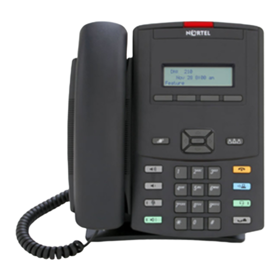
Chapter 2 • 10/100 Ethernet ports — Ethernet port for LAN connection — Ethernet port for optional PC connection • Power over Ethernet (PoE) or power through a supported AC adapter • wall-mounted In addition, the IP Phone 1220 and IP Phone 1230 models have the following features: •... - Page 15 Figure 1 IP Phone 1210 Message waiting indicator/ Incoming call indicator Display screen Soft keys (4) Programmable keys (2) Navigation keys Goodbye key Applications key Headset key Hold key Dialpad Volume control keys Mute key Handsfree key IP Phone 1200 Series Installation...
- Page 16 Chapter 2 Figure 2 IP Phone 1220 User-defined feature keys (4) Message waiting indicator/ Incoming call indicator Display screen Soft keys (4) Programmable keys (6) Navigation keys Goodbye key Applications key Headset key Hold key Dialpad Volume control keys Mute key Handsfree key NN40050-302...
- Page 17 (10) Message waiting indicator/ Incoming call indicator Display screen Soft keys (4) Programmable keys (6) Navigation keys Goodbye key Applications key Headset key Hold key Dialpad Volume control keys Mute key Handsfree key IP Phone 1200 Series Installation...
- Page 18 Chapter 2 Table 3 IP Phone 1210, 1220, and 1230 keys descriptions (Sheet 1 of 2) Key or component Description Message waiting indicator/ When a message is waiting, the red message waiting indicator flashes. Incoming call indicator Also, when the ringer sounds, this indicator flashes. User-defined feature keys The keys on either side of the display area are programmable keys with (not available on the IP Phone...
-
Page 19: Keycap Defaults
You can order your IP Phone 1210, 1220, and 1230 with one set of keycaps. Table 4 “Keycap defaults” (page 19) shows the two sets of keycaps available. Table 4 Keycap defaults (Sheet 1 of 2) Function Iconic keycap Textual keycap Conference Services Quit IP Phone 1200 Series Installation... -
Page 20: Display Screen
Chapter 2 Table 4 Keycap defaults (Sheet 2 of 2) Function Iconic keycap Textual keycap Message Directory Redial Increase volume Decrease volume Mute Handsfree Goodbye Applications Headset Hold Display screen Your IP Phone 1210, 1220, and 1230 have two or three display areas, depending on the model you are using: •... -
Page 21: Rear View Of Ip Phone
Ethernet port, PC Ethernet port, AEM port, and an AC power port, as shown in Figure 5 “IP Phone ports” (page 21). You can also attach a foot stand to the IP Phone 1200 series phones. You can attach the foot stand in one of two positions, as shown in Figure 6 “Foot stand positions”... -
Page 22: Expansion Modules For The Ip Phone 1210, 1220, And 1230
Chapter 2 Figure 6 Foot stand positions Bottom tabs Position 1 slots (25-degree angle) Position 2 slots (55-degree angle) Expansion modules for the IP Phone 1210, 1220, and 1230 This section provides information about the LCD Expansion Module:12-Key Self-Labeling and the LED Expansion Module:18-Key Paper Label. -
Page 23: Keys And Descriptions
For a description of the keys and components on your expansion modules, see the Table 5 “Expansion module key descriptions” (page 24). Some keys or components are not available on all expansion modules. Figure 7 LCD Expansion Module: 12-Key Self Labeling User-defined feature keys Display (LCD) IP Phone 1200 Series Installation... - Page 24 Chapter 2 Figure 8 LED Expansion Module: 18-Key Paper Label User-defined feature key LEDs User-defined feature keys Labels Table 5 Expansion module key descriptions Key or component Description User-defined feature keys The keys on the Expansion Modules are programmable keys with an LCD display or paper labels.
-
Page 25: Ip Phone Installation
PC Ethernet port. Navigation • “Attaching the foot stand (optional)” on page 26 • “Connecting the handset” on page 27 • “Connecting the headset (optional)” on page 27 • “Connecting the power (optional)” on page 28 IP Phone 1200 Series Installation... -
Page 26: Attaching The Foot Stand (Optional)
Chapter 3 • “Connecting the LAN Ethernet cable” on page 28 • “Connecting the PC Ethernet cable” on page 29 • “Wall-mounting the IP Phone (optional)” on page 29 Attaching the foot stand (optional) Attach the foot stand in the appropriate slots depending on the desired angle for your IP Phone. If you insert the foot stand into the upper slots, your IP Phone sits at a 25-degree angle. -
Page 27: Connecting The Handset
Connecting the headset (optional) If you have a headset, you can connect the headset to the IP Phone. For information on how to use your headset with your IP Phone, see the IP Phone 1200 Series User Guide (NN40010-302). Procedure steps... -
Page 28: Connecting The Power (Optional)
Your IP Phone supports both AC power and Power over Ethernet (PoE). For AC power, use only the Nortel-approved Global Power Supply (N0146475) and the country-specific IEC cable that you can order separately. To use PoE, your connected LAN must support PoE. -
Page 29: Connecting The Pc Ethernet Cable
Insert the screws (not provided) so that they protrude slightly from the wall. Align the keyholes on the back of the IP Phone with the screws in the wall. Slide the IP Phone down on the screws to secure the IP Phone in position. IP Phone 1200 Series Installation... - Page 30 Chapter 3 NN40050-302...
-
Page 31: Expansion Module Installation
Chapter 4 Expansion module installation Complete the procedures in this chapter to install the expansion modules for IP Phone 1200 series phones. The procedures in this section are applicable to both the LCD Expansion Module:12-Key Self-Labeling and the LED Expansion Module:18-Key Paper Label. -
Page 32: Installing The Expansion Module
Chapter 4 Installing the expansion module CAUTION Risk of damage to equipment To avoid damaging the equipment, remove the power (PoE cable or local power) from the IP Phone before you connect the expansion module. Procedure steps Step Action Remove power from the IP Phone. Remove the IP Phone from the foot stand. -
Page 33: Installing Additional Expansion Modules
Align the connecting tabs of the second expansion module with the connecting slots on the back of the first expansion module. Repeat steps 1 through 6 for each subsequent expansion module you add. IP Phone 1200 Series Installation... -
Page 34: Attaching The Foot Stand
Chapter 4 Attaching the foot stand Attach the foot stand in the appropriate slots depending on the desired angle for your IP Phone and expansion modules. If you are installing your IP Phone and expansion modules on a wall, do not attach the foot stand. -
Page 35: Wall-Mounting The Ip Phone With One Or More Expansion Modules (Optional)
Align the keyholes on the back of the IP Phone and expansion modules with the screws in the wall. Slide the IP Phone and the expansion modules down on the screws to secure the phone in position. IP Phone 1200 Series Installation... - Page 36 Chapter 4 NN40050-302...
-
Page 37: Ip Phone Registration
Chapter 5 IP Phone registration Ensure that you have loaded the appropriate BCM keycodes to activate the Nortel IP Phone 1200 series phones on your BCM system. Navigation • “Determining the registration process” on page 37 • “Registering the IP Phone (global registration with password)” on page 38 •... -
Page 38: Registering The Ip Phone (Global Registration With Password)
Step Action Restart the phone by disconnecting and reconnecting the power. After about 4 seconds, the top light flashes and NORTEL appears on the screen. When the greeting appears, immediately and quickly press the four soft keys directly under the display one at a time, from left to right. -
Page 39: Moving An Ip Phone And Changing The Dn
Deregister the DN through the Business Element Manager. Disconnect the network connection and the power connection from the IP Phone. Reinstall the IP Phone at the new location. Reconfigure the IP Phone. Register the new DN through the Business Element Manager. IP Phone 1200 Series Installation... - Page 40 Chapter 5 NN40050-302...
-
Page 41: Ip Phone Configuration
The Lock Menu tool is not available on all systems. If the menu entry appears dimmed, it is not enabled on your phone. Contact your system administrator to find out of this feature is available for your use. IP Phone 1200 Series Installation... -
Page 42: Local Preferences Configuration
Chapter 6 Local preferences configuration Use the Preferences menu to configure local preferences, including display settings and language. Changing the display settings Use the Contrast tool to change the physical settings of the display. Procedure steps Step Action Double-press (Services) quickly to open the Local Tools menu. Press 1 on the dial pad to open the Preferences menu. -
Page 43: Diagnostic Tasks
Press 2 on the dial pad to open the Local Diagnostics menu. Press 2 on the dial pad to open the Ntwrk Diagnostic Tools menu. Press the Up/Down navigation keys to scroll through and view the settings. Press Return to keep existing configurations. IP Phone 1200 Series Installation... -
Page 44: Viewing Ethernet Statistics
Chapter 6 Viewing Ethernet statistics Use the Ethernet statistics tool to view reports about Ethernet operation. This menu is for administrator use only. Procedure steps Step Action Double-press (Services) quickly to open the Local Tools menu. Press 2 on the dial pad to open the Local Diagnostics menu. Press 3 on the dial pad to open the Ethernet Statistics menu. -
Page 45: Viewing Configuration Information
(Services) quickly to open the Local Tools menu. Press 4 on the dial pad to open the Lock Menu option. Enter the password. Press Select to lock the menus. Press Cancel to keep the existing configuration. IP Phone 1200 Series Installation... - Page 46 Chapter 6 NN40050-302...