Gree GMV-ND100L/A-T Service Manual
Multi variable air conditioners indoor units
Hide thumbs
Also See for GMV-ND100L/A-T:
- Service manual (227 pages) ,
- Owner's manual (35 pages) ,
- Owner's manual (56 pages)
Table of Contents
Advertisement
Advertisement
Table of Contents

Related Manuals for Gree GMV-ND100L/A-T


Summary of Contents for Gree GMV-ND100L/A-T
- Page 1 Multi Variable Air Conditioners Indoor Units (GC201809-VI)
-
Page 2: Table Of Contents
Contents PRODUCT ........................... 1 1 Product List ........................2 1.1 Floor Standing Type ....................... 2 1.2 High Static Pressure Duct Type ..................... 2 1.3 Low Static Pressure Duct Type ....................3 1.4 4-way Cassette ........................3 1.5 Compact 4-way Cassette ....................... 4 1.6 2-way Cassette ........................ - Page 3 1 Operation Flowchart ..................... 46 2 Wired Controller ......................47 2.1 Control panel ........................47 2.2 Installation and removal ....................... 49 3 Remote Controller......................52 3.1 Remote controller YAP1F ....................52 3.2 Remote controller YV1L1 ..................... 53 4 Panel Display ........................ 54 4.1 Control Panel ........................
- Page 4 3.11 Installation of Wall-Mounted Unit ..................114 3.12 Console Type Indoor Unit ....................118 3.13 Installation of Super High Static Pressure Duct Type Indoor Unit ........119 3.14 Installation of AHU-KIT Type .................... 121 3.15 Installation of Concealed Floor Standing Type ..............124 4 Installation of drain pipe ....................
- Page 5 4.6 2-way Cassette Type ......................167 4.7 1-way Cassette Type ......................168 4.8 Floor Ceiling Type ......................171 4.9 Fresh air Processing Unit....................172 4.10 Slim Duct Type ........................ 176 4.11 Console Type Indoor Unit ....................177 4.12 Wall Mounted type Indoor Unit ..................179 4.13 Super High Static Pressure Duct Type Indoor Unit ............
-
Page 6: Product
GREE GMV5 INDOOR UNIT SERVICE MANUAL PRODUCT... -
Page 7: Product List
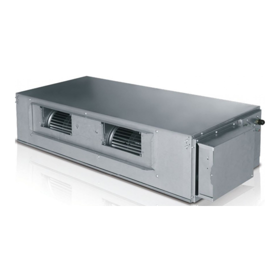
GMV5 INDOOR UNIT SERVICE MANUAL 1 Product List 1.1 Floor Standing Type Cooling Heating Power Capacity Capacity Model Product Code Refrigerant Appearance Supply GMV-ND100L/A-T CM300N0060 10.0 11.0 220- 240V~50Hz R410A 208- 230V~60Hz GMV-ND140L/A-T CM300N0070 14.0 15.0 1.2 High Static Pressure Duct Type... -
Page 8: Low Static Pressure Duct Type
GREE GMV5 INDOOR UNIT SERVICE MANUAL 1.3 Low Static Pressure Duct Type Cooling Heating Power Capacity Capacity Model Product Code Refrigerant Appearance Supply GMV- CM800N3370 ND22PLS/A-T GMV- CM800N3380 ND25PLS/A-T GMV- CM800N3490 ND28PLS/A-T GMV- CM800N3390 ND32PLS/A-T GMV- CM800N3500 ND36PLS/A-T GMV- CM800N3400... -
Page 9: Compact 4-Way Cassette
GREE GMV5 INDOOR UNIT SERVICE MANUAL 1.5 Compact 4-way Cassette Cooling Heating Power Capacity Capacity Model Product Code Refrigerant Appearance Supply GMV-ND22T/B-T CM500N0610 GMV-ND28T/B-T CM500N0620 220- GMV-ND36T/B-T CM500N0630 240V~50Hz R410A 208- GMV-ND45T/B-T CM500N0640 230V~60Hz GMV-ND50T/B-T CM500N0600 GMV-ND56T/B-T CM500N0650 1.6 2-way Cassette... -
Page 10: Fresh Air Processing
GREE GMV5 INDOOR UNIT SERVICE MANUAL 1.9 Fresh air Processing Cooling Heating Power Capacity Capacity Model Product Code Refrigerant Appearance Supply 220- GMV-NX140P/A(X1.2)-K CM800N3610 14.0 10.0 240V/1~50Hz GMV-NX224P/A(X2.0) -M CM800N3620 22.4 16.0 GMV-NX280P/A(X2.5) -M CM800N3630 28.0 20.0 380- GMV-NX280P/A(X3.0) -M CM800N3640 28.0... -
Page 11: Air Handler Type Indoor Unit
GREE GMV5 INDOOR UNIT SERVICE MANUAL 1.11 Air Handler type Indoor Unit Cooling Heating Power Capacity Capacity Model Product Code Refrigerant Appearance Supply GMV-NR71A/A-D CM810N0200 GMV-NR90A/A-D CM810N0210 10.0 208- GMV-NR100A/A-D CM810N0220 10.0 11.0 R410A 230V~60Hz GMV-NR112A/A-D CM810N0230 11.2 12.5 GMV-NR140A/A-D CM810N0240 14.0... - Page 12 GREE GMV5 INDOOR UNIT SERVICE MANUAL Cooling Heating Product Power Model Refrigerant Appearance Capacit Capacit Code Supply GMV-N22G/A8A-K CM100N1770 GMV-N28G/A8A-K CM100N1780 GMV-N36G/A8A-K CM100N1790 GMV-N45G/A8A-K CM100N1800 220- 240V~50Hz GMV-N50G/A8A-K CM100N1810 GMV-N56G/A8A-K CM100N1820 GMV-N63G/A8A-K CM100N1830 GMV-N71G/A8A-K CM100N1840 GMV-N22G/B3A-K CM100N2460 GMV-N28G/B3A-K CM100N2470 GMV-N36G/B3A-K...
- Page 13 GREE GMV5 INDOOR UNIT SERVICE MANUAL Cooling Heating Power Capacity Capacity Model Product Code Refrigerant Appearance Supply GMV-N22G/A2A-D CM100N1930 GMV-N28G/A2A-D CM100N1940 GMV-N36G/A2A-D CM100N1950 GMV-N45G/A2A-D CM100N1960 208- R410A 230V~60Hz GMV-N50G/A2A-D CM100N1970 GMV-N56G/A2A-D CM100N1980 GMV-N63G/A2A-D CM100N1990 GMV-N71G/A2A-D CM100N2000 GMV-N22G/A4A-D CM100N1610 GMV-N28G/A4A-D CM100N1620...
-
Page 14: Super High Static Pressure Duct Type Indoor Unit
GREE GMV5 INDOOR UNIT SERVICE MANUAL Cooling Heating Power Capacity Capacity Model Product Code Refrigerant Appearance Supply GMV-ND22G/A3A-T CM100N2560 GMV-ND28G/A3A-T CM100N2600 GMV-ND36G/A3A-T CM100N2590 GMV-ND45G/A3A-T CM100N2580 220- GMV-ND50G/A3A-T CM100N2610 240V~50Hz GMV-ND56G/A3A-T CM100N2570 R410A 208- GMV-ND63G/A3A-T CM100N2550 230V~60Hz GMV-ND71G/A3A-T CM100N2540 GMV-ND80G/A3A-T CM100N2620... -
Page 15: Ahu-Kit Type
GMV-ND71ZA/A-T CM810N1430 2 Nomenclature 2.1 Nomenclature of indoor units □ □ □ □ □ □ □ Description Options Product code GMV-Gree Multi VRF Units indoor unit code indoor unit -N D – DC motor Motor type NULL – AC motor... -
Page 16: Specifications
② DC inverter fresh air processing indoor, airflow volume ranging from 2000m³ /h to 3500m³ /h are available, there’s not “(X+figure)”at the end of model. 3 Specifications 3.1 Floor Standing Type Model GMV-ND100L/A-T GMV-ND140L/A-T Cooling capacity 10.0 14.0 Heating capacity 11.0... -
Page 17: High Static Pressure Duct Type
GREE GMV5 INDOOR UNIT SERVICE MANUAL Model GMV-ND100L/A-T GMV-ND140L/A-T Φ9.52 Φ9.52 Liquid Connection Method Bell mouth connection Bell mouth connection Net weight Note: ① Units conform to design standard: ISO 15042-2011. ② Specifications may be changed due to product improvement. Please refer to nameplates of the units. - Page 18 GREE GMV5 INDOOR UNIT SERVICE MANUAL GMV- GMV- GMV- GMV-ND80 GMV-ND90 GMV- Model ND56PHS/A- ND63PHS/A- ND71PHS/A- PHS/A-T PHS/A-T ND100PHS/A-T External Drain Φ20×1.2 Φ20×1.2 Φ20×1.2 Φ20×1.2 Φ20×1.2 Φ20×1.2 diameter pipe ×thickness Unit Dimensions 1271×558 1271×558 1271×558 1271×558 1229×775 1229×775 (mm)(W×D×H) ×268 ×268...
-
Page 19: Low Static Pressure Duct Type
GREE GMV5 INDOOR UNIT SERVICE MANUAL 3.3 Low Static Pressure Duct Type GMV- GMV- GMV- GMV- GMV- GMV- GMV- GMV- GMV- Model ND22P ND25P ND28P ND32P ND36P ND40P ND45P ND50P ND56P LS/A-T LS/A-T LS/A-T LS/A-T LS/A-T LS/A-T LS/A-T LS/A-T LS/A-T... -
Page 20: 4-Way Cassette Type
GREE GMV5 INDOOR UNIT SERVICE MANUAL GMV- GMV- GMV- GMV- GMV- GMV- GMV- GMV- Model ND63PL ND71PL ND80PL ND90PL ND100P ND112PL ND125P ND140P S/A-T S/A-T S/A-T S/A-T LS/A-T S/A-T LS/A-T LS/A-T External Φ25×2.5 Φ25×2.5 Φ25×2.5 Φ25×2.5 Φ25×2.5 Φ25×2.5 Φ25×2.5 Φ25×2.5... -
Page 21: Compact 4-Way Cassette Type
GREE GMV5 INDOOR UNIT SERVICE MANUAL GMV- GMV- GMV- GMV- GMV- GMV- GMV- Model ND80T/A-T ND90T/A-T ND100T/A-T ND112T/A-T ND125T/A-T ND140T/A-T ND160T/A-T Horse Power Cooling capacity 10.0 11.2 12.5 14.0 16.0 Heating capacity 10.0 11.2 12.5 14.0 16.0 17.5 Air volume... -
Page 22: 2-Way Cassette Type
GREE GMV5 INDOOR UNIT SERVICE MANUAL GMV- GMV- GMV- GMV- GMV- GMV- Model ND22T/B-T ND28T/B-T ND36T/B-T ND45T/B-T ND50T/B-T ND56T/B-T Heating current input *Minimum line current 0.63 0.63 0.63 *Maximum fuse current Sound pressure level dB(A) Power supply** 220-240V 1 phase ~50Hz/208-230V 1 phase ~60Hz Φ6.35... -
Page 23: 1-Way Cassette Type
GREE GMV5 INDOOR UNIT SERVICE MANUAL GMV- GMV- GMV- GMV- GMV- GMV- GMV- Model ND28TS/A- ND36TS/A- ND45TS/A- ND50TS/A- ND56TS/A- ND63TS/A- ND71TS/A- Power supply** 220-240V 1 phase ~50Hz/208-230V 1 phase ~60Hz Φ6.35 Φ6.35 Φ6.35 Φ6.35 Φ9.52 Φ9.52 Φ9.52 Liquid pipe Piping Φ9.52... -
Page 24: Floor Ceiling Type
GREE GMV5 INDOOR UNIT SERVICE MANUAL GMV- GMV- GMV- GMV- GMV- GMV- Model ND22TD/A-T ND28TD/A-T ND36TD/A-T ND45TD/A-T ND50TD/A-T ND56TD/A-T Main body W×D×H mm 987×385×178 987×385×178 987×385×178 987×385×178 987×385×178 987×385×178 dimensions Panel W×D×H mm 1200×460×55 1200×460×55 1200×460×55 1200×460×55 1200×460×55 1200×460×55 dimensions... -
Page 25: Fresh Air Processing Unit
GREE GMV5 INDOOR UNIT SERVICE MANUAL GMV- GMV- GMV- GMV- GMV- Model ND90ZD/A-T ND112ZD/A-T ND125ZD/A-T ND140ZD/A-T ND160ZD/A-T Heating capacity 10.0 12.5 14.0 16.0 18.0 Air volume 1600 2000 2000 2000 2300 Cooling power input Cooling current input Heating power input... - Page 26 GREE GMV5 INDOOR UNIT SERVICE MANUAL GMV- GMV- GMV- GMV- GMV- Model NX140P/A NX224P/A NX280P/A NX280P/A NX450P/A (X1.2)-K (X2.0) -M (X2.5) -M (X3.0) -M (X4.0) -M Maximum fuse current Sound pressure level dB(A) 220-240V 380-415V 380-415V 380-415V 380-415V Power supply...
- Page 27 GREE GMV5 INDOOR UNIT SERVICE MANUAL Model GMV-NDX250P/A-T GMV-NDX280P/A-T Air volume 2500/2000~3500 2500/2000~3500 Standard Static pressure (Pa) Optional 50~300 50~300 Rated power input Rated current input Cooling power input Cooling current input Heating power input Heating current input Maximum fuse current...
-
Page 28: Slim Duct Type
GREE GMV5 INDOOR UNIT SERVICE MANUAL 3.10 Slim Duct Type GMV- GMV- GMV- GMV- GMV- GMV- Model ND22PL/B-T ND25PL/B-T ND28PL/B-T ND32PL/B-T ND36PL/B-T ND40PL/B-T Horse Power Cooling capacity Heating capacity Air volume Unit external static pressure 0/0~15 0/0~15 0/0~15 0/0~15 0/0~15... - Page 29 GREE GMV5 INDOOR UNIT SERVICE MANUAL GMV- GMV- GMV- GMV- GMV- GMV- Model ND22PLS/B1 ND25PLS/B1 ND28PLS/B1 ND32PLS/B1 ND36PLS/B1 ND40PLS/B1 Heating capacity Air volume Unit external static pressure 10/30 10/30 10/30 10/30 10/30 10/30 Cooling power input Cooling current input 0.30 0.30...
-
Page 30: Air Handler Type Indoor Unit
GREE GMV5 INDOOR UNIT SERVICE MANUAL range of unit. 3.11 Air Handler type Indoor Unit GMV- GMV- GMV- GMV- GMV- Model NR71A/A-D NR90A/A-D NR100A/A-D NR112A/A-D NR140A/A-D Horse Power Cooling capacity 10.0 11.2 14.0 Heating capacity 10.0 11.0 12.5 15.0 Air volume... -
Page 31: Console Type Indoor Unit
GREE GMV5 INDOOR UNIT SERVICE MANUAL 3.12 Console Type Indoor Unit GMV-ND22C/A- GMV-ND28C/A- GMV-ND36C/A- GMV-ND45C/A- GMV-ND50C/A- Model Horse Power Cooling capacity Heating capacity Air volume Cooling power input Cooling current input 0.17 0.17 0.25 0.25 Heating power input Heating current input 0.17... -
Page 32: Wall Mounted Type Indoor Unit
GREE GMV5 INDOOR UNIT SERVICE MANUAL Wall Mounted type 3.13 Wall Mounted type Indoor Unit GMV- GMV- GMV- GMV- GMV- Model N22G/A3A-K N28G/A3A-K N36G/A3A-K N45G/A3A-K N50G/A3A-K Horse Power Cooling capacity Heating capacity Air volume Cooling power input Cooling current input 0.31... - Page 33 GREE GMV5 INDOOR UNIT SERVICE MANUAL Model GMV-N56G/A3A-K GMV-N63G/A3A-K GMV-N71G/A3A-K *Maximum fuse current Sound pressure level dB(A) Power supply 220-240V 1 phase ~50Hz Φ9.52 Φ9.52 Φ9.52 Liquid pipe Piping Φ15.9 Φ15.9 Φ15.9 interface Gas pipe External diameter Φ30×1.5 Φ30×1.5 Φ30×1.5 Drain pipe ×...
- Page 34 GREE GMV5 INDOOR UNIT SERVICE MANUAL GMV- GMV- GMV- GMV- GMV- Model N22G/A2A-K N28G/A2A-K N36G/A2A-K N45G/A2A-K N50G/A2A-K Horse Power Cooling capacity Heating capacity Air volume Cooling power input Cooling current input 0.31 0.31 0.31 Heating power input Heating current input 0.31...
- Page 35 GREE GMV5 INDOOR UNIT SERVICE MANUAL GMV- GMV- GMV- GMV- GMV- Model N22G/A4A-K N28G/A4A-K N36G/A4A-K N45G/A4A-K N50G/A4A-K Heating current input 0.31 0.31 0.31 *Minimum line current 0.25 0.25 0.38 0.38 0.38 *Maximum fuse current Sound pressure level dB(A) Power supply 220-240V 1 phase ~50Hz Φ6.35...
- Page 36 GREE GMV5 INDOOR UNIT SERVICE MANUAL GMV- GMV- GMV- GMV- GMV- Model N22G/A8A-K N28G/A8A-K N36G/A8A-K N45G/A8A-K N50G/A8A-K Φ6.35 Φ6.35 Φ6.35 Φ6.35 Φ6.35 Liquid pipe Piping Φ9.52 Φ9.52 Φ12.7 Φ12.7 Φ12.7 interface Gas pipe External diameter Φ20×1.5 Φ20×1.5 Φ20×1.5 Φ20×1.5 Φ20×1.5 Drain pipe ×thickness...
- Page 37 GREE GMV5 INDOOR UNIT SERVICE MANUAL Model GMV-N56G/ C9A -K GMV-N63G/ C9A -K GMV-N71G/ C9A -K Horse Power Cooling capacity Heating capacity Air volume Cooling power input Cooling current input 0.31 0.31 0.31 Heating power input Heating current input 0.31 0.31...
- Page 38 GREE GMV5 INDOOR UNIT SERVICE MANUAL Model GMV-N56G/ E3A -K GMV-N63G/ E3A -K GMV-N71G/ E3A -K *Minimum line current *Maximum fuse current Sound pressure level dB(A) Power supply 220-240V 1 phase ~50Hz Φ9.52 Φ9.52 Φ9.52 Liquid pipe Piping Φ15.9 Φ15.9 Φ15.9...
- Page 39 GREE GMV5 INDOOR UNIT SERVICE MANUAL Model GMV-N22G/A2A-D GMV-N28G/A2A-D GMV-N36G/A2A-D GMV-N45G/A2A-D Horse Power Cooling capacity Heating capacity Air volume Cooling power input Cooling current input 0.21 0.21 Heating power input Heating current input 0.21 0.21 *Minimum line current 0.25 0.25 0.38...
- Page 40 GREE GMV5 INDOOR UNIT SERVICE MANUAL Model GMV-N22G/A4A-D GMV-N28G/A4A-D GMV-N36G/A4A-D GMV-N45G/A4A-D *Maximum fuse current Sound pressure level dB(A) Power supply 208-230V~60Hz Φ6.35 Φ6.35 Φ6.35 Φ6.35 Liquid pie Piping Φ9.52 Φ9.52 Φ12.7 Φ12.7 interface Gas pipe Outer diameter Φ20×1.5 Φ20×1.5 Φ20×1.5 Φ20×1.5...
- Page 41 GREE GMV5 INDOOR UNIT SERVICE MANUAL Model GMV-N50G/A8A-D GMV-N56G/A8A-D GMV-N63G/A8A-D GMV-N71G/A8A-D Horse Power Cooling capacity Heating capacity Air volume Cooling power input 0.31 0.31 Cooling current input 0.21 0.31 Heating power input 0.31 0.31 Heating current input 0.21 0.31 *Minimum line current 0.38...
- Page 42 GREE GMV5 INDOOR UNIT SERVICE MANUAL Model GMV-N50G/C9A-D GMV-N56G/C9A-D GMV-N63G/C9A-D GMV-N71G/C9A-D *Maximum fuse current Sound pressure level dB(A) Power supply 208-230V~60Hz Φ6.35 Φ9.52 Φ9.52 Φ9.52 Liquid pie Piping Φ12.7 Φ15.9 Φ15.9 Φ15.9 interface Gas pipe Outer diameter Φ20×1.5 Φ30×1.5 Φ30×1.5 Φ30×1.5...
- Page 43 GREE GMV5 INDOOR UNIT SERVICE MANUAL Model GMV-N22G/B3A-D GMV-N28G/B3A-D GMV-N36G/B3A-D GMV-N45G/B3A-D Horse Power Cooling capacity Heating capacity Air volume Cooling power input Cooling current input 0.21 0.21 Heating power input Heating current input 0.21 0.21 *Minimum line current 0.25 0.25 0.38...
- Page 44 GREE GMV5 INDOOR UNIT SERVICE MANUAL GMV- GMV- GMV- GMV- GMV- GMV- Model ND22G/A3A- ND28G/A3A- ND36G/A3A- ND45G/A3A- ND50G/A3A- ND56G/A3A- *Minimum line current 0.15 0.15 0.15 *Maximum fuse current Sound pressure level dB(A) Power supply 220-240V 1 phase ~50Hz/208-230V 1 phase ~60Hz Φ6.35...
- Page 45 GREE GMV5 INDOOR UNIT SERVICE MANUAL GMV- GMV- GMV- GMV- GMV- GMV- Model ND22G/A8A- ND28G/A8A- ND36G/A8A- ND45G/A8A- ND50G/A8A- ND56G/A8A- Φ6.35 Φ6.35 Φ6.35 Φ6.35 Φ6.35 Φ9.52 Liquid pipe Piping Φ9.52 Φ9.52 Φ12.7 Φ12.7 Φ12.7 Φ15.9 interface Gas pipe External diameter Φ20×1.5 Φ20×1.5...
-
Page 46: Super High Static Pressure Duct Type Indoor Unit
GREE GMV5 INDOOR UNIT SERVICE MANUAL 3.14 Super High Static Pressure Duct Type Indoor Unit GMV- GMV- GMV- GMV- GMV- GMV- Model ND22PHS/B ND25PHS/B ND28PHS/B ND32PHS/B ND36PHS/B ND40PHS/B Horse Power Cooling capacity Heating capacity Air Volume External Static Pressure 60/0~150... - Page 47 GREE GMV5 INDOOR UNIT SERVICE MANUAL GMV- GMV- GMV- GMV- GMV- GMV- Model ND90PHS/B- ND100PHS/ ND112PHS/ ND125PHS/ ND140PHS/ ND160PHS/ Horse Power Cooling capacity 10.0 11.2 12.5 14.0 16.0 Heating capacity 10.0 11.2 12.5 14.0 16.0 18.0 Air Volume 1800 1800...
-
Page 48: Ahu-Kit Type
GREE GMV5 INDOOR UNIT SERVICE MANUAL 3.15 AHU-KIT Type Model GMV-N36U/A-T GMV-N71U/A-T GMV-N140U/A-T Capacity Defaulted capacity of Cooling 14.0 ex-factory Heating 16.0 Capacity Adjustable capacity Cooling 11.2 14.0 Heating 10.0 12.5 16.0 Power input Power Supply V/Ph/Hz 220~240/1/50 & 08~230/1/60 AHU-KIT Φ6.35... -
Page 49: Concealed Floor Standing Type
GREE GMV5 INDOOR UNIT SERVICE MANUAL GMV-N560U/A- GMV-N560U/A- GMV-N560U/A- Model(Combined) T+GMV-N140U/A-T T+GMV-N280U/A-T T+GMV-N560U/A-T (W×D×H) (334×284×111)×2 (334×284×111)×2 (334×284×111)×2 Control box Net weight 11.8+8.6 11.8+8.6 11.8+11.8 3.16 Concealed Floor Standing Type GMV- GMV- GMV- GMV- GMV- GMV- GMV- Model ND22ZA/A- ND28ZA/A- ND36ZA/A-... -
Page 50: Control
GREE GMV5 INDOOR UNIT SERVICE MANUAL CONTROL... -
Page 51: Operation Flowchart
GREE GMV5 INDOOR UNIT SERVICE MANUAL 1 Operation Flowchart... -
Page 52: Wired Controller
GREE GMV5 INDOOR UNIT SERVICE MANUAL 2 Wired Controller 2.1 Control panel Fig.2.1 Appearance of wired controller Fig2.2 LED graphics of wired controller Table 2.1 LED display instruction Symbols Instructions Up and down swing function Left and right swing function It's valid under Save mode and displays during setting process. - Page 53 GREE GMV5 INDOOR UNIT SERVICE MANUAL Symbols Instructions Auto mode (Under Auto mode, the indoor units will automatically select their operating mode as per the temperature change so as to make the ambient comfortable.) It shows the setting temperature value (In case the wired controller is controlling a...
-
Page 54: Installation And Removal
GREE GMV5 INDOOR UNIT SERVICE MANUAL Symbols Instructions Outdoor unit defrosting status Gate-control function Shielding status Child Lock status One wired controller controls multiple indoor units Save status of indoor unit It indicates the current wired controller is the slave wired controller (address of wired... - Page 55 GREE GMV5 INDOOR UNIT SERVICE MANUAL 2.2.2 Installation method Fig.2.5 Installation of Wired Controller Above is a simple installation method of wired controller. Please pay attention to the following: Before installation, disconnect power of the indoor unit. Do not operate when power is connected.
- Page 56 GREE GMV5 INDOOR UNIT SERVICE MANUAL 2.2.4 Connection of communication cord There are 4 ways to connect wired controller with indoor units’ network: Fig.2.7 One wired controller controls one indoor unit Fig.2.8 Two wired controllers control one indoor unit Fig.2.9 One wired controller controls multiple indoor units simultaneously...
-
Page 57: Remote Controller
GREE GMV5 INDOOR UNIT SERVICE MANUAL Fig.2.10 Two wired controllers control multiple indoor units simultaneously Note: Floor standing indoor unit only applicable to Fig.2.7. 3 Remote Controller 3.1 Remote controller YAP1F... -
Page 58: Remote Controller Yv1L1
GREE GMV5 INDOOR UNIT SERVICE MANUAL Button name and function introduction Button name Function ON/OFF Turn on or turn off the unit TURBO Set turbo function MODE Set operation mode Set up&down swing status I FEEL Set I FEEL function Switch temperature displaying type on the unit’s display... -
Page 59: Panel Display
GREE GMV5 INDOOR UNIT SERVICE MANUAL Button name Function Set up&down swing status X-FAN Set X-FAN function TIMER ON Set timer on function TIMER OFF Set timer off function SAVE Set energy-saving function SLEEP Set sleep function LIGHT Set light function... - Page 60 GREE GMV5 INDOOR UNIT SERVICE MANUAL (2) Under power-on or power-off status, press “Light” button to turn on and turn off the light of display panel. (3) When the light of display panel is turned off, press the other buttons other than “Light” button, the light on display panel will be turned off after 5 seconds.
- Page 61 GREE GMV5 INDOOR UNIT SERVICE MANUAL status. After quiting the function setting status, the “ ” icon is on, it means the timer function has been turned on. Cancel timer: press “Function” button to switch to timer function, when “...
- Page 62 GREE GMV5 INDOOR UNIT SERVICE MANUAL (7) Setting of energy-saving function Energy-saving function: through setting the lower temperature limit of cooling and dry mode and upper temperature limit of heating mode, to make the air conditioner operate in a smaller temperature range, thus save energy.
-
Page 63: Introduction To Unit Functions
GREE GMV5 INDOOR UNIT SERVICE MANUAL only unit will display “nC”, heating only uint will display “nH”, swing type unit will display “nF”. (3) Setting of power-fail memory function Under power-off status, simultaneously press “Mode” button and “▲” button for 5 seconds to switch the memory method: if “88”... -
Page 64: Engineering Application Functions Operated Through The Xk46 Wired Controller
GREE GMV5 INDOOR UNIT SERVICE MANUAL Function Name User parameter settings Engineering parameter query Engineering parameter settings Engineering application functions can be operated through the IDU wired controller (XK46 or XK49 or XK79) or remote controller (YV1L1, fittings selectable). 5.1 Engineering Application Functions Operated through the XK46 Wired Controller 5.1.1 Master IDU Settings... - Page 65 GREE GMV5 INDOOR UNIT SERVICE MANUAL parameter setting interface. Step 3: Press “▲” or “▼” to switch level 2 parameter codes till “P10” is displayed on the temperature area. Step 4: Press the “MODE” button to set the parameter to “01” and then Press the “ENTER” button.
- Page 66 GREE GMV5 INDOOR UNIT SERVICE MANUAL Press and hold the “FUNCTION” button for five seconds in power-on or power-off status to enter the parameter query interface “C00”. Continuously press the “MODE” button for three times, and then press and hold the “FUNCTION” button for five seconds to enter the engineering parameter setting interface.
- Page 67 GREE GMV5 INDOOR UNIT SERVICE MANUAL Parameter Parameter Parameter Name View Method Code Range Operation method: In “C06” status, press the “MODE” button to enter the preferential operation query interface. Press “ ” or “ ” to 00: common switch the IDU SN.
- Page 68 GREE GMV5 INDOOR UNIT SERVICE MANUAL Parameter Parameter Parameter Name View Method Code Range Operation method: In “C18” status, press the “MODE” button to enter the IDU project number query interface. Press “▲” or “▼” to switch the IDU SN.
- Page 69 GREE GMV5 INDOOR UNIT SERVICE MANUAL settings. (4) The user parameter setting list is as follows: Table 2.2 User Parameter Setting List Parameter Parameter Default Parameter Range Remark Code Name Value 00: does not change the After the IDU connected...
- Page 70 GREE GMV5 INDOOR UNIT SERVICE MANUAL Parameter Parameter Default Parameter Range Remark Code Name Value Cooling setting temperature in 17° C -30° C Cooling setting temperature – heating automatic setting temperature ≥ 1. mode Note: The two settings are still valid in...
- Page 71 GREE GMV5 INDOOR UNIT SERVICE MANUAL 5.1.5 Engineering Parameter Query Engineering parameters can be queried in power-on or power-off status. Press and hold the “FUNCTION” button for five seconds to enter the engineering parameter query interface. The temperature area displays “C00” and “View” is on.
- Page 72 GREE GMV5 INDOOR UNIT SERVICE MANUAL Parameter Parameter Parameter Name View Method Code Range Operation method: In “C14” status, press the “MODE” button to enter inlet-tube temperature sensor query of IDU. Press “ ” or “ ” to switch the IDU SN.
- Page 73 GREE GMV5 INDOOR UNIT SERVICE MANUAL Parameter Parameter Parameter Name View Method Code Range Operation method: In “n6” status, press the “MODE” button to enter fault code query of ODU (when a wired controller controls multiple IDUs, only the faults memorized by the IDU that has the minimum project number can be queried).
- Page 74 GREE GMV5 INDOOR UNIT SERVICE MANUAL Parameter Parameter Parameter Name View Method Code Range Subcooler EXV (Actual value = Displayed value * Defrosting temperature ° C Liquid-extracting temperature of ° C subcooler Outlet temperature of accumulator ° C Oil return temperature °...
- Page 75 GREE GMV5 INDOOR UNIT SERVICE MANUAL Parameter Parameter Parameter Name View Method Code Range It indicates the former 0128 seven bits of the bar code. It indicates the latter six bits of the bar code. Note: 1. Un indicates the entire-unit bar code of IDU and Pc indicates the controller bar code of IDU.
- Page 76 GREE GMV5 INDOOR UNIT SERVICE MANUAL Parameter Parameter Name Parameter Range Default Value Remark Code 01: temperature sensor When there are master and slave of air return vent wired controllers and the 02: temperature sensor temperature sensor of wired of wired controller...
- Page 77 GREE GMV5 INDOOR UNIT SERVICE MANUAL Parameter Parameter Name Parameter Range Default Value Remark Code In “P42” status, press the “MODE” button to enter the setting menu. Automatically The project number blinks in the timer area. Press “ ” or “ ” to...
- Page 78 GREE GMV5 INDOOR UNIT SERVICE MANUAL Parameter Parameter Name Parameter Range Default Value Remark Code Enter query in “A7” status. The 00: no silent function 01-09: intelligent temperature area displays the Silent function of nighttime silent mode function code and the timer area...
-
Page 79: Engineering Application Functions Operated Through The Xk49 Wired Controller
GREE GMV5 INDOOR UNIT SERVICE MANUAL 5.2 Engineering Application Functions Operated through the XK49 Wired Controller XK49 Wired Controller 5.2.1 Master IDU Settings Method 1: In power-off status, press and hold the “MODE” button for five seconds to set the IDU connected with the current wired controller to master IDU. - Page 80 GREE GMV5 INDOOR UNIT SERVICE MANUAL (1) Press and hold the “MODE” button and “SWING” simultaneously for five seconds to enter the user parameter query interface. The temperature area displays “C00” and “View” is on. (2) Select a parameter code by pressing “ ” or “ ”.
-
Page 81: Engineering Application Functions Operated Through The Xk79 Wired Controller
GREE GMV5 INDOOR UNIT SERVICE MANUAL to enter the wired controller engineering parameter setting interface. The temperature area displays “P00”. (2) Select a parameter code by pressing “ ” or “ ”. Press the “MODE” button to switch to parameter value settings. The parameter value blinks. Adjust the parameter value by pressing “... - Page 82 GREE GMV5 INDOOR UNIT SERVICE MANUAL Method 2: Step 1: Press and hold the “FUNCTION” button for five seconds in power-on or power-off status to enter the parameter query interface. Step 2: Press and hold the “FUNCTION” button for five seconds in “C00” status to enter the parameter setting interface.
- Page 83 GREE GMV5 INDOOR UNIT SERVICE MANUAL 5.3.2 User Parameter Query User parameters can be queried in power-on or power-off status. (1) Press and hold the “FUNCTION” button for five seconds to enter the user parameter query interface. The temperature area displays “C00” and “View” is on.
- Page 84 GREE GMV5 INDOOR UNIT SERVICE MANUAL (1) Press and hold the “FUNCTION” button for five seconds. The temperature area displays “C00”. Continuously press the “MODE” button for three times, and then press and hold the “FUNCTION” button for another five seconds to enter the wired controller engineering parameter setting interface.
-
Page 85: Engineering Application Functions Operated Through The Yv1L1 Remote Controller
GREE GMV5 INDOOR UNIT SERVICE MANUAL 5.4 Engineering Application Functions Operated through the YV1L1 Remote Controller The YV1L1 remote controller provides all engineering application functions. It is set to common type by default upon factory departure. It can use engineering application functions only after being set to professional type. - Page 86 GREE GMV5 INDOOR UNIT SERVICE MANUAL Button name Function SLEEP Set sleep function LIGHT Set light function CLOCK Set clock of the system I FEEL Set I FEEL function Switch temperature displaying type on the unit’s display TEMP 5.4.1 Master IDU Settings The master IDU can be set through the wired controller or remote controller.
- Page 87 GREE GMV5 INDOOR UNIT SERVICE MANUAL Query Code Query Content Query Sub-item Level 2 Query Content Fault 1 Fault 2 Historical fault query ingress of the current Fault 3 Fault 4 Fault 5 Preferential operation query Temperature query for environment temperature sensor of the current IDU...
- Page 88 GREE GMV5 INDOOR UNIT SERVICE MANUAL Press “ ” to change the parameter value. (4) Press “ ” to confirm query and return to step 2. After entering engineering commissioning, the system automatically quits the engineering commissioning status if no valid operations are performed within 20 seconds. To directly quit the engineering commissioning status, press “...
- Page 89 GREE GMV5 INDOOR UNIT SERVICE MANUAL Setting Code Setting Content Setting Value 50: 50 seconds 60: 60 seconds Project number settings of 1-255 Preferential operation 00: no preferential operation settings 01: preferential operation One-key project number 00: not displayed setting query for IDU...
-
Page 90: Engineering Application Functions Operated Through The Yap1F Remote Controller
GREE GMV5 INDOOR UNIT SERVICE MANUAL 5.5 Engineering Application Functions Operated through the YAP1F Remote Controller The YAP1F remote controller only provides engineering application functions for setting the master IDU. For other user operation functions, refer to the “Remote Controller Operating Instructions”. -
Page 91: Installation
GREE GMV5 INDOOR UNIT SERVICE MANUAL INSTALLATION... -
Page 92: Engineering Installation Preparation And Notice
GREE GMV5 INDOOR UNIT SERVICE MANUAL 1 Engineering Installation Preparation and Notice 1.1 Installation notice Personnel and property safety are highly concerned during the entire installation process. Installation implementation must abide by relevant national safety regulations to ensure personnel and property safety. -
Page 93: Installation Materials Selection
GREE GMV5 INDOOR UNIT SERVICE MANUAL Installation Problem Possible Consequence The ratio of slop for condensate water pipe is insufficient or the Reverse slop or inconsistent connection of condensate water pipe can hinder the condensate water pipe is smooth drainage and cause leakage of the IDU. -
Page 94: Condensate Water Pipe
GREE GMV5 INDOOR UNIT SERVICE MANUAL Specifications requirement R410A Refrigerant System OD (mm/inch) Wall Thickness (mm) Model Φ6.35(1/4) ≥0.8 Φ9.52(3/8) ≥0.8 Φ12.70(1/2) ≥0.8 Φ15.9(5/8) ≥1.0 Φ19.05(3/4) ≥1.0 (5) After the inner part of the copper pipe is cleaned and dried, the inlet and outlet must be sealed tightly by using pipe caps, plugs or adhesive tapes. -
Page 95: Power Cable
GREE GMV5 INDOOR UNIT SERVICE MANUAL Communication cable selection for IDU and wired controller Total length of communication Cable Wire size Material Material type Remarks between IDU unit and /AWG) standard wired controller L(m/ft) 1. Total length of communication line can't exceed 250m (820- 1/5ft). - Page 96 Please contact the local Gree appointed service center before installation. Any malfunctioncaused by the unit that is not installed by the Gree appointed service center would probably not be dealt with on time because of the inconvenience of the business contact.
-
Page 97: Installation Of High Static Pressure Duct Type Unit
GREE GMV5 INDOOR UNIT SERVICE MANUAL 3.2 Installation of High Static Pressure Duct Type unit 3.2.1 Outline and installation dimension Model: GMV-ND56PHS/A-T~ GMV-ND160PHS/A-T Below are dimensions of A, B, C, etc. for different models: Unit: mm/inch Model GMV-ND56PHS/A-T GMV-ND63PHS/A-T 1101... - Page 98 GREE GMV5 INDOOR UNIT SERVICE MANUAL Model : GMV-ND224PH/A-T , GMV-ND280PH/A-T Below are dimensions of A, B, C, etc. for different models: Unit: mm/inch Model 1353 1150 GMV-ND224PH/A-T (53-1/4) (24-7/8) (39) (45-1/4) (7-1/2) (12-7/8) 1563 1350 GMV-ND280PH/A-T (61-1/8) (27-3/4) (39)
- Page 99 Please contact the local Gree appointed service center before installation. Any malfunctioncaused by the unit that is not installed by the Gree appointed service center would probably not be dealt with on time because of the inconvenience of the business contact.
-
Page 100: Installation Of Low Static Pressure Duct Type Unit
GREE GMV5 INDOOR UNIT SERVICE MANUAL Minimum Sectional Minimum Sectional Air Switch apacity Model Power Cord Size Area of Ground Wire Area of Power Cord /AWG) /AWG) 220-240V/50Hz GMV-ND160PHS/A-T 1.0/AWG18 1.0/AWG18 208-230V/60Hz 220-240V/50Hz GMV-ND224PH/A-T 1.0/AWG18 1.0/AWG18 208-230V/60Hz 220-240V/50Hz GMV-ND280PH/A-T 1.0/AWG18 1.0/AWG18... - Page 101 GREE GMV5 INDOOR UNIT SERVICE MANUAL Model: GMV-ND71PLS/A-T~GMV-ND140PLS/A-T Below are dimensions of A, B, C etc. for different models: Unit:mm Model GMV-ND71PLS/A-T 1236 1200 1016 1050 GMV-ND80PLS/A-T GMV-ND90PLS/A-T GMV-ND100PLS/A-T GMV-ND112PLS/A-T 1379 1340 1153 1188 GMV-ND125PLS/A-T GMV-ND140PLS/A-T GMV-ND63PLS/A-T 3.3.2 Installation space Unit: mm 3.3.3 Installation notice...
- Page 102 Please contact the local Gree appointed service center before installation. Any malfunctioncaused by the unit that is not installed by the Gree appointed service center would probably not be dealt with on time because of the inconvenience of the business contact.
-
Page 103: Installation Of 4-Way Cassette Type Unit
GREE GMV5 INDOOR UNIT SERVICE MANUAL 3.4 Installation of 4-way Cassette Type unit 3.4.1 Outline and installation dimension Model 28~140 1040 3.4.2 Installation space 3.4.3 Installation notice The unit shall be installed by the professional personnel according to this installation instruction... - Page 104 Please contact the local Gree appointed service center before installation. Any malfunctioncaused by the unit that is not installed by the Gree appointed service center would probably not be dealt with on time because of the inconvenience of the business contact.
-
Page 105: Installation Of Compact 4-Way Cassette Type Unit
GREE GMV5 INDOOR UNIT SERVICE MANUAL 3.5 Installation of Compact 4-way Cassette Type unit 3.5.1 Outline and installation dimension Outer Diameter of Drainage Connection Pipe(mm) Pipe(Outer Model A (mm) B (mm) C (mm) D (mm) E (mm) F (mm) Diameter× wall... - Page 106 Please contact the local Gree appointed service center before installation. Any malfunctioncaused by the unit that is not installed by the Gree appointed service center would probably not be dealt with on time because of the inconvenience of the business contact.
-
Page 107: Installation Of Compact 2-Way Cassette Type Unit
The unit shall be installed by the professional personnel according to this installation instruction to ensure proper use. Please contact the local Gree appointed service center before installation. Any malfunctioncaused by the unit that is not installed by the Gree appointed service center would... -
Page 108: Installation Of Compact 1-Way Cassette Type Unit
GREE GMV5 INDOOR UNIT SERVICE MANUAL probably not be dealt with on time because of the inconvenience of the business contact. It should be guided under the professional personnel when the air conditioner unit is moved to other place. - Page 109 Please contact the local Gree appointed service center before installation. Any malfunctioncaused by the unit that is not installed by the Gree appointed service center would probably not be dealt with on time because of the inconvenience of the business contact.
-
Page 110: Installation Of Floor Ceiling Type Unit
GREE GMV5 INDOOR UNIT SERVICE MANUAL 3.8 Installation of Floor Ceiling Type unit 3.8.1 Outline and installation dimension Below are dimensions of A, B, C, etc. for different models: Unit: mm Outer diameter of Drainage pipe(Outer connection pipe(mm) Models: A(mm) - Page 111 Please contact the local Gree appointed service center before installation. Any malfunctioncaused by the unit that is not installed by the Gree appointed service center would probably not be dealt with on time because of the inconvenience of the business contact.
-
Page 112: Installation Of Fresh Air Processing Unit
GREE GMV5 INDOOR UNIT SERVICE MANUAL Minimum Sectional Minimum Sectional Air Switch apacity Model Power Cord Size Area of Ground Wire Area of Power Cord /AWG) /AWG) 220-240V/50Hz GMV-ND63ZD/A-T 1.0/AWG18 1.0/AWG18 208-230V/60Hz 220-240V/50Hz GMV-ND71ZD/A-T 1.0/AWG18 1.0/AWG18 208-230V/60Hz 220-240V/50Hz GMV-ND90ZD/A-T 1.0/AWG18 1.0/AWG18... - Page 113 GREE GMV5 INDOOR UNIT SERVICE MANUAL GMV-NX450P/A(X4.0)-M GMV-NDX125P/A-T、GMV-NDX140P/A-T The table below lists the detailed dimensions. Unit: mm Model GMV-NDX125P/A-T 1440 1530 1400 GMV-NDX140P/A-T 1440 1530 1400...
- Page 114 GREE GMV5 INDOOR UNIT SERVICE MANUAL GMV-NDX224P/A-T、GMV-NDX250P/A-T 、GMV-NDX280P/A-T The table below lists the detailed dimensions. Unit: mm Item Model GMV-NDX224P/A-T 1353 1150 GMV-NDX250P/A-T 1353 1150 GMV-NDX280P/A-T 1353 1150 3.9.2 Installation space Note: ① Installation of the unit must be in accordance with National Electric Codes and local safety regulations.
- Page 115 Please contact the local Gree appointed service center before installation. Any malfunctioncaused by the unit that is not installed by the Gree appointed service center would probably not be dealt with on time because of the inconvenience of the business contact.
-
Page 116: Installation Of Slim Duct Type Unit
Please contact the local Gree appointed service center before installation. Any malfunctioncaused by the unit that is not installed by the Gree appointed service center would probably not be dealt with on time because of the inconvenience of the business contact. -
Page 117: Installation Of Air Handler Type Indoor Unit
GREE GMV5 INDOOR UNIT SERVICE MANUAL Installation of the unit must be in accordance with National Electric Codes and local regulations. Improper installation will affect unit’s performance, so do not install the unit by yourself. Please contact local dealer to arrange professional technicians for the installation. - Page 118 GREE GMV5 INDOOR UNIT SERVICE MANUAL Unit: mm DIMENSION MODEL GMV-NR71A/A-D 1105 GMV-NR90A/A-D 1105 GMV-NR100A/A-D 1224 GMV-NR112A/A-D 1224 GMV-NR140A/A-D 1224 3.10.2 Installation notice When installing the air handler, take consideration to minimize the length of refrigerant tubing as much as possible. Do not install the air handler in a location either above or below the condenser that violates the instructions provided with the condenser.
-
Page 119: Installation Of Wall-Mounted Unit
GREE GMV5 INDOOR UNIT SERVICE MANUAL 3.10.3 Selection of air switch and power cord Minimum Sectional Minimum Sectional Circuit Breaker Model Power Supply Area of Ground Wire Area of Power Cord Capacity (A) /AWG) /AWG) GMV-NR71A/A-D 208-230V~60Hz 1.0/AWG18 1.0/AWG18 GMV-NR90A/A-D 208-230V~60Hz 1.0/AWG18... - Page 120 GREE GMV5 INDOOR UNIT SERVICE MANUAL Item Model GMV-N56G/A3A-K, GMV-N63G/A3A-K, GMV-N71G/A3A-K, GMV-N56G/A2A-K, GMV-N63G/A2A-K, GMV-N71G/A2A-K, GMV-N56G/A4A-K, GMV-N63G/A4A-K, GMV-N71G/A4A-K, GMV-N56G/A8A-K, GMV-N63G/A8A-K, GMV-N71G/A8A-K GMV-N56G/C9A-K, GMV-N63G/C9A-K, GMV-N71G/C9A-K, GMV-N56G/E3A-K, GMV-N63G/E3A-K, GMV-N71G/E3A-K, GMV-N56G/B3A-K, GMV-N63G/B3A-K, GMV-N71G/B3A-K, GMV-N56G/A3A-D, GMV-N63G/A3A-D, GMV-N71G/A3A-D 1008 GMV-N56G/A2A-D, GMV-N63G/A2A-D, GMV-N71G/A2A-D, GMV-N56G/A4A-D, GMV-N63G/A4A-D, GMV-N71G/A4A-D, GMV-N56G/A8A-D, GMV-N63G/A8A-D,...
- Page 121 GREE GMV5 INDOOR UNIT SERVICE MANUAL Minimum Sectional Area of Minimum Sectional Area of Air Switch apacity Model Power Cord Size Ground Wire Power Cord /AWG) /AWG) GMV-N28G/A3A-K, GMV-N28G/A2A-K GMV-N28G/A4A-K, 220-240V ~ GMV-N28G/A8A-K 1.0/AWG18 1.0/AWG18 50Hz GMV-N28G/C9A-K, GMV-N28G/E3A-K GMV-N28G/B3A-K, GMV-N36G/A3A-K,...
- Page 122 GREE GMV5 INDOOR UNIT SERVICE MANUAL Minimum Sectional Area of Minimum Sectional Area of Air Switch apacity Model Power Cord Size Ground Wire Power Cord /AWG) /AWG) GMV-N22G/A3A-D, GMV-N22G/A2A-D GMV-N22G/A4A-D, 208~230V ~ GMV-N22G/A8A-D 1.0/AWG18 1.0/AWG18 60Hz GMV-N22G/C9A-D, GMV-N22G/E3A-D GMV-N22G/B3A-D, GMV-N28G/A3A-D,...
-
Page 123: Console Type Indoor Unit
GREE GMV5 INDOOR UNIT SERVICE MANUAL Air Switch Minimum Sectional Area of Minimum Sectional Area of Model Power Cord Size apacity Ground Wire Power Cord /AWG) /AWG) GMV-ND22G/A3A-T, 220-240V~50Hz 1.0/AWG18 1.0/AWG18 GMV-ND22G/A8A-T /208-230V~60Hz GMV-ND28G/A3A-T, 220-240V~50Hz 1.0/AWG18 1.0/AWG18 GMV-ND28G/A8A-T /208-230V~60Hz GMV-ND36G/A3A-T, 220-240V~50Hz 1.0/AWG18... -
Page 124: Installation Of Super High Static Pressure Duct Type Indoor Unit
GREE GMV5 INDOOR UNIT SERVICE MANUAL tightly. Notes: ① Be careful in bending the connection pipes, or you would damage the pipes. ② If the tightening torque for the flare nut is too great, leakage would happen. 3.12.4 Selection of air switch and power cord... - Page 125 Please contact the local Gree appointed service center before installation. Any malfunctioncaused by the unit that is not installed by the Gree appointed service center would probably not be dealt with on time because of the inconvenience of the business contact.
-
Page 126: Installation Of Ahu-Kit Type
GREE GMV5 INDOOR UNIT SERVICE MANUAL Minimum Sectional Area Minimum Sectional Area Air Switch apacity Model Power Cord Size of Ground Wire of Power Cord /AWG) /AWG) 220-240V/50Hz GMV-ND36PHS/B-T 1.0/AWG18 1.0/AWG18 208-230V/60Hz 220-240V/50Hz GMV-ND40PHS/B-T 1.0/AWG18 1.0/AWG18 208-230V/60Hz 220-240V/50Hz GMV-ND45PHS/B-T 1.0/AWG18 1.0/AWG18... - Page 127 GREE GMV5 INDOOR UNIT SERVICE MANUAL (2) Size of EXV box for GMV-N36U/A-T, GMV-N71U/A-T, GMV-N140U/A-T and GMV-N280U/A-T (Unit: mm): (3) Size of EXV box for GMV-N560U/A-T (Unit: mm):...
- Page 128 GREE GMV5 INDOOR UNIT SERVICE MANUAL 3.14.2 Installation space (1) Maintenance space of control space (Unit: mm): (2) Maintenance space of EXV box (Unit: mm): 3.14.3 Installation notice The EXV box can be installed inside and outside. The control box should be installed inside.
-
Page 129: Installation Of Concealed Floor Standing Type
GREE GMV5 INDOOR UNIT SERVICE MANUAL maintenance. The installation site should be far away from heat source, inflammable gas and smoke. Keep the air handling unit, power supply wiring and transmission wiring at least 1 m away from televisions and radios. - Page 130 The unit shall be installed by the professional personnel according to this installation instruction to ensure proper use. Please contact the local Gree appointed service center before installation. Any malfunctioncaused by the unit that is not installed by the Gree appointed service center would...
-
Page 131: Installation Of Drain Pipe
GREE GMV5 INDOOR UNIT SERVICE MANUAL probably not be dealt with on time because of the inconvenience of the business contact. It should be guided under the professional personnel when the air conditioner unit is moved to other place. -
Page 132: Installing The Drain Pipes
GREE GMV5 INDOOR UNIT SERVICE MANUAL (4) Keep piping as short as possible and slope it downwards at a gradient of at least 1/100 so that air may not remain trapped inside the pipe. For example: (5) Keep pipe size equal to or greater than that of the connecting pipe. - Page 133 GREE GMV5 INDOOR UNIT SERVICE MANUAL ◆ Install one water trap for each unit ◆ Installation of water trap shall consider easy cleaning in the future. ◆ Connection of drainage branch pipe to the standpipe or horizontal pipe of drainage main pipe ◆...
-
Page 134: Precautions When Doing Riser Piping Work
GREE GMV5 INDOOR UNIT SERVICE MANUAL ◆ When unifying multiple drain pipes, install the pipes as shown below. Select converging drain pipes whose gauge is suitable for the operating capacity of the unit (take the cassette type unit for example). -
Page 135: Testing Of Drain Piping
GREE GMV5 INDOOR UNIT SERVICE MANUAL 4.4 Testing of Drain Piping ◆ After piping work is finished, check if drainage flows smoothly. ◆ Shown in the figure, Add approximately 1liter of water slowly into the drain pan and check drainage flow during COOL running. -
Page 136: Maintenance
GREE GMV5 INDOOR UNIT SERVICE MANUAL Maintenance... -
Page 137: Troubleshooting
GREE GMV5 INDOOR UNIT SERVICE MANUAL 1 Troubleshooting 1.1 Malfunction list for the wired controller Display Display Display Content Content Content code code code Wrong number of indoor Malfunction of Malfunction of water unit for one-to-more indoor indoor unit temperature sensor... - Page 138 GREE GMV5 INDOOR UNIT SERVICE MANUAL Possible reason: ■Poor contact between ambient temperature sensor and terminal in mainboard interface ■Ambient temperature sensor is abnormal ■Detecting circuit is abnormal Troubleshooting: 1.2.3 “d4” Inlet pipe temperature sensor error Error display: IDU wired controller and IDU receive light board will display...
- Page 139 GREE GMV5 INDOOR UNIT SERVICE MANUAL 1.2.4 “d6” Outlet pipe temperature sensor error Error display: IDU wired controller and IDU receive light board will display Error judgment condition and method: Sample the AD value of temperature sensor through temperature sensor detecting circuit and judge the range of AD value.
- Page 140 GREE GMV5 INDOOR UNIT SERVICE MANUAL Troubleshooting: 1.2.6 “d9” Jumper cap error Error display: IDU wired controller and IDU receive light board will display Error judgment condition and method: Possible reason: If jumper cap model doesn’t match with mainboard, report the error ■Jumper cap is not installed...
- Page 141 GREE GMV5 INDOOR UNIT SERVICE MANUAL 1.2.7 “dA” IDU network address error Error display: IDU wired controller and IDU receive light board will display Error judgment condition and method: Through testing the IDU address chip and IP address, if address chip cannot be read, IDU IP is 0 or IP is in conflict, report the error.
- Page 142 GREE GMV5 INDOOR UNIT SERVICE MANUAL 1.2.9 “dC” Capacity DIP switch setting error Error display: IDU wired controller and IDU receive light board will display Error judgment condition and method: If capacity DIP switch is set to the wrong position, report the error.
- Page 143 GREE GMV5 INDOOR UNIT SERVICE MANUAL 1.2.11 “db” Project debugging Error display: ODU mainboard, IDU wired controller and IDU receive light board will display Error judgment condition and method: This is a status code of project debugging, not a error code. When IDU or ODU displays this code, it means the unit is under debugging status and the IDU cannot be operated.
- Page 144 GREE GMV5 INDOOR UNIT SERVICE MANUAL Troubleshooting: 1.2.13 “L3” Water full protection Error display: IDU wired controller and IDU receive light board will display Error judgment condition and method: Check the status of IDU float switch. When water level is too high, float switch is activated, so water...
- Page 145 GREE GMV5 INDOOR UNIT SERVICE MANUAL full protection happens. Possible reason: ■IDU is installed improperly ■Drainage pump is broken ■Float switch operates abnormally ■IDU mainboard is abnormal Troubleshooting:...
- Page 146 GREE GMV5 INDOOR UNIT SERVICE MANUAL 1.2.14 “L4” Power supply overcurrent protection Error display: IDU wired controller and IDU receive light board will display Error judgment condition and method: Check if the power supply current from IDU to wired controller is normal. If power supply current is too big, it is judged that the current is abnormal.
- Page 147 GREE GMV5 INDOOR UNIT SERVICE MANUAL Troubleshooting: 1.2.16 “L7” No master IDU Error display: IDU wired controller and IDU receive light board will display Error judgment condition and method: No master IDU error will happen when there is no master IDU in the system Possible reason: ■Master IDU is offline...
- Page 148 GREE GMV5 INDOOR UNIT SERVICE MANUAL Troubleshooting: 1.2.17 “L9” Group-controlled IDU quantity inconsistency Error display: IDU wired controller and IDU receive light board will display Error judgment condition and method: If the IDU quantity connected with wired controller exceeds 16 sets or actually connected IDU quantity is inconsistent with the set group-controlled IDU quantity.
-
Page 149: After-Sales Emergency Masures
GREE GMV5 INDOOR UNIT SERVICE MANUAL Troubleshooting: Make sure the IDUs connected with one wired controller belong to the same series. 1.2.19 “LC” Mismatch of IDU and ODU models Error display: IDU wired controller and IDU receive light board will display... -
Page 150: Floor Standing Type
GREE GMV5 INDOOR UNIT SERVICE MANUAL 3.1 Floor Standing Type GMV-ND100L/A-T, GMV-ND140L/A-T 3.2 High Static Pressure Duct Type GMV-ND56PHS/A-T, GMV-ND63PHS/A-T, GMV-ND71PHS/A-T, GMV-ND80PHS/A-T, GMV-ND90PHS/A-T, GMV-ND100PHS/A-T, GMV-ND112PHS/A-T, GMV-ND125PHS/A-T, GMV-ND140PHS/A-T:... - Page 151 GREE GMV5 INDOOR UNIT SERVICE MANUAL GMV-ND160PHS/A-T: GMV-ND224PH/A-T, GMV-ND280PH/A-T:...
-
Page 152: Low Static Pressure Duct Type
GREE GMV5 INDOOR UNIT SERVICE MANUAL 3.3 Low Static Pressure Duct Type GMV-ND22PLS/A-T, GMV-ND25PLS/A-T, GMV-ND28PLS/A-T, GMV-ND32PLS/A-T, GMV-ND36PLS/A-T, GMV-ND40PLS/A-T, GMV-ND45PLS/A-T, GMV-ND50PLS/A-T, GMV-ND56PLS/A-T, GMV-ND63PLS/A-T, GMV-ND71PLS/A-T, GMV-ND80PLS/A-T: GMV-ND90PLS/A-T, GMV-ND100PLS/A-T, GMV-ND112PLS/A-T, GMV-ND125PLS/A-T, GMV-ND140PLS/A-T:... -
Page 153: 4-Way Cassette Type
GREE GMV5 INDOOR UNIT SERVICE MANUAL 3.4 4-way Cassette Type GMV-ND28T/A-T, GMV-ND36T/A-T, GMV-ND45T/A-T, GMV-ND50T/A-T, GMV-ND56T/A-T, GMV-ND63T/A-T, GMV-ND71T/A-T, GMV-ND80T/A-T: GMV-ND90T/A-T, GMV-ND100T/A-T, GMV-ND112T/A-T, GMV-ND125T/A-T, GMV-ND140T/A-T:... -
Page 154: Compact 4-Way Cassette Type
GREE GMV5 INDOOR UNIT SERVICE MANUAL GMV-ND160T/A-T: 3.5 Compact 4-way Cassette Type GMV-ND22T/B-T, GMV-ND28T/B-T, GMV-ND36T/B-T, GMV-ND45T/B-T, GMV-ND50T/B-T, GMV-ND56T/B-T... -
Page 155: 2-Way Cassette Type
GREE GMV5 INDOOR UNIT SERVICE MANUAL 3.6 2-way Cassette Type GMV-ND28TS/A-T, GMV-ND36TS/A-T, GMV-ND45TS/A-T, GMV-ND50TS/A-T, GMV-ND56TS/A-T, GMV-ND63TS/A-T, GMV-ND71TS/A-T: Earthing wire is available for iron-clad motor, while unavailable for plastic-clad motor. 3.7 1-way Cassette Type GMV-ND22TD/A-T, GMV-ND28TD/A-T, GMV-ND36TD/A-T, GMV-ND45TD/A-T, GMV-ND50TD/A-T, GMV-ND56TD/A-T GMV-ND71TSA-T 63620050047 ±1. -
Page 156: Floor Ceiling Type
GREE GMV5 INDOOR UNIT SERVICE MANUAL 3.8 Floor Ceiling Type GMV-ND28ZD/A-T, GMV-ND36ZD/A-T, GMV-ND50ZD/A-T, GMV-ND56ZD/A-T, GMV-ND63ZD/A-T, GMV-ND71ZD/A-T, GMV-ND90ZD/A-T, GMV-ND112ZD/A-T, GMV-ND125ZD/A-T, GMV-ND140ZD/A-T, GMV-ND160ZD/A-T:... -
Page 157: Fresh Air Processing Unit
GREE GMV5 INDOOR UNIT SERVICE MANUAL 3.9 Fresh air Processing Unit GMV-NX140P/A(X1.2)-K: GMV-NX224P/A(X2.0)-M, GMV-NX280P/A(X2.5)-M, GMV-NX280P/A(X3.0)-M:... - Page 158 GREE GMV5 INDOOR UNIT SERVICE MANUAL GMV-NX450P/A(X4.0)-M: GMV-NDX125P/A-T, GMV-NDX140P/A-T INDOOR UNIT Electronic Inductor expansion POWER valve CN19 CN20 Communication JUMP cord interface CN12 Wired controller interface YEGN CN25 CN26 CN27 CN28 CN35 Wired Outdoor or controller indoor Note1 5-core Electronic expansion Motor valve connect to CN20;...
-
Page 159: Slim Duct Type
GREE GMV5 INDOOR UNIT SERVICE MANUAL GMV-NDX224P/A-T, GMV-NDX250P/A-T, GMV-NDX280P/A-T 3.10 Slim Duct Type GMV-ND22PL/B-T, GMV-ND25PL/B-T, GMV-ND28PL/B-T, GMV-ND32PL/B-T, GMV-ND36PL/B-T, GMV-ND40PL/B-T, GMV-ND45PL/B-T, GMV-ND50PL/B-T, GMV-ND56PL/B-T, GMV-ND63PL/B-T, GMV- ND72PL/B-T, GMV-ND22PLS/B1-T, GMV-ND25PLS/B1-T, GMV-ND28PLS/B1-T, GMV-ND32PLS/B1-T, GMV-ND36PLS/B1-T, GMV-ND40PLS/B1-T, GMV-ND45PLS/B1-T, GMV-ND50PLS/B1-T, GMV- ND56PLS/B1-T, GMV-ND63PLS/B1-T, GMV-ND71PLS/B1-T... -
Page 160: Air Handler Type Indoor Unit
GREE GMV5 INDOOR UNIT SERVICE MANUAL 3.11 Air Handler type Indoor Unit GMV-NR71A/A-D, GMV-NR90A/A-D, GMV-NR100A/A-D, GMV-NR112A/A-D, GMV-NR140A/A-D... -
Page 161: Console Type Indoor Unit
GREE GMV5 INDOOR UNIT SERVICE MANUAL 3.12 Console Type Indoor Unit GMV-ND22C/A-T, GMV-ND28C/A-T, GMV-ND36C/A-T, GMV-ND45C/A-T, GMV-ND50C/A-T 3.13 Wall Mounted type Indoor Unit... -
Page 162: Super High Static Pressure Duct Type Indoor Unit
GREE GMV5 INDOOR UNIT SERVICE MANUAL 3.14 Super High Static Pressure Duct Type Indoor Unit GMV-ND22PHS/B-T, GMV-ND25PHS/B-T, GMV-ND28PHS/B-T, GMV-ND32PHS/B-T, GMV- ND36PHS/B-T, GMV-ND40PHS/B-T, GMV-ND45PHS/B-T, GMV-ND50PHS/B-T, GMV-ND56PHS/B-T, GMV-ND63PHS/B-T, GMV-ND71PHS/B-T, GMV-ND80PHS/B-T: GMV-ND90PHS/B-T, GMV-ND100PHS/B-T, GMV-ND112PHS/B-T, GMV-ND125PHS/B-T:... -
Page 163: Ahu-Kit Type
GREE GMV5 INDOOR UNIT SERVICE MANUAL GMV-ND140PHS/B-T, GMV-ND160PHS/B-T: 3.15 AHU-KIT Type GMV-N36U/A-T, GMV-N71U/A-T, GMV-N140U/A-T, GMV-N280U/A-T, GMV-N560U/A-T... -
Page 164: Concealed Floor Standing Type
GREE GMV5 INDOOR UNIT SERVICE MANUAL 3.16 Concealed Floor Standing Type GMV-ND22ZA/A-T, GMV-ND28ZA/A-T, GMV-ND36ZA/A-T, GMV-ND45ZA/A-T, GMV-ND56ZA/A-T、 GMV-ND63ZA/A-T, GMV-ND71ZA/A-T 4 Disassembly And Assembly Procedure Of Main Parts 4.1 Floor Standing Type Removal and Assembly of electric box Remarks: Before removing the electric box, make sure to cut off the power firstly. -
Page 165: High Static Pressure Duct Type
GREE GMV5 INDOOR UNIT SERVICE MANUAL Removal and Assembly of electric box Remarks: Before removing the electric box, make sure to cut off the power firstly. Step Illustration Handling Instruction 2. Unscrew the screws on Unscrew the screws on the bottom... - Page 166 GREE GMV5 INDOOR UNIT SERVICE MANUAL Motor and fan Precondition: The power supply has been disconnected. Step Diagram Operation Procedure ●Use a screwdriver to unscrew the 3. Remove the cover plate component. cover plate component. ●Use a screwdriver to unscrew the 4.
-
Page 167: Low Static Pressure Duct Type
GREE GMV5 INDOOR UNIT SERVICE MANUAL 4.3 Low Static Pressure Duct Type Note: The following steps are specific for GMV-ND22PLS/A-T units. For other units, the assembly and disassembly procedure is similar except the numbers of centrifugal fans and motors. Motor and fan Precondition: The power supply has been disconnected. -
Page 168: 4-Way Cassette Type
GREE GMV5 INDOOR UNIT SERVICE MANUAL 4.4 4-way Cassette Type Motor and fan Step Diagram Operation Procedure ●Use a screwdriver to unscrew the 1. Unscrew the water tray. water tray. Water tray ●Remove the water tray. 2. Remove the water tray. - Page 169 GREE GMV5 INDOOR UNIT SERVICE MANUAL Motor and fan Step Diagram Operation Procedure ●Install the centrifugal fan and use 8. Install and screw the a wrench to screw the centrifugal centrifugal fan. fan. Tighten the screws ●Use a screwdriver to screw the 9.
-
Page 170: Compact 4-Way Cassette Type
GREE GMV5 INDOOR UNIT SERVICE MANUAL 4.5 Compact 4-way Cassette Type Motor and fan Step Diagram Operation Procedure ●Use a screwdriver to unscrew the 1. Unscrew the water tray. water tray. ●Remove the water tray. 2. Remove the water tray. - Page 171 GREE GMV5 INDOOR UNIT SERVICE MANUAL Motor and fan Step Diagram Operation Procedure ●Use a screwdriver to screw the 7. Screw the motor. motor. ●Install the centrifugal fan and use 8. Install and screw the a wrench to screw the centrifugal centrifugal fan.
-
Page 172: 2-Way Cassette Type
GREE GMV5 INDOOR UNIT SERVICE MANUAL Pump Step Diagram Operation Procedure ●Replace the pump. 4. Replace the pump. ●Connect the drainage duct and 5. Connect the drainage duct and screw the new use a screwdriver to screw the pump. new pump. -
Page 173: 1-Way Cassette Type
GREE GMV5 INDOOR UNIT SERVICE MANUAL Removal of Fan Motor Precondition: The power supply has been disconnected. Step Diagram Operation Procedure ●Remove the volute casing ●Use a hexagon to unscrew the 4. Remove the centrifugal centrifugal fan,remove it from motor axle ●Assemble units based on the... - Page 174 GREE GMV5 INDOOR UNIT SERVICE MANUAL Motor and fan Step Diagram Operation Procedure 4. Remove the volute ●Remove the volute tongue. tongue. ●Use a screwdriver to unscrew the 5. Unscrew the outlet board. outlet board and then remove the board.
- Page 175 GREE GMV5 INDOOR UNIT SERVICE MANUAL Motor and fan Step Diagram Operation Procedure ●Install the evaporator. 10. Install the evaporator. ●Use a screwdriver to screw the 11. Screw the outlet board. outlet board. ●Put the volute tongue back to 12. Put the volute tongue back to position.
-
Page 176: Floor Ceiling Type
GREE GMV5 INDOOR UNIT SERVICE MANUAL 4.8 Floor Ceiling Type Note: The following steps are specific for GMV-ND140ZD/A-T units. For other units, the assembly and disassembly procedure is similar except the numbers of centrifugal fans and motors. Motor and fan Precondition: The power supply has been disconnected. -
Page 177: Fresh Air Processing Unit
GREE GMV5 INDOOR UNIT SERVICE MANUAL Motor and fan Precondition: The power supply has been disconnected. Step Diagram Operation Procedure ●Loosen the fasteners that 8. Remove the centrifugal connect the coupler with the motor fan. axle and remove the centrifugal fan. - Page 178 GREE GMV5 INDOOR UNIT SERVICE MANUAL Motor and fan Precondition: The power supply has been disconnected. Step Diagram Operation Procedure ●Remove the motor from the support and remove the louver 4. Remove the motor. from the motor axle. Then, remove the motor.
- Page 179 GREE GMV5 INDOOR UNIT SERVICE MANUAL Motor and fan Precondition: The power supply has been disconnected. Step Diagram Operation Procedure ●Assemble units based on the 5.Install a new motor. reverse order of this procedure and power on the units for test.
- Page 180 GREE GMV5 INDOOR UNIT SERVICE MANUAL Motor and fan Precondition: The power supply has been disconnected. Step Diagram Operation Procedure ●Remove the filter from the air 2. Remove the filter. And the return frame. ●Use a screwdriver to unscrew the air return cover plate.
-
Page 181: Slim Duct Type
GREE GMV5 INDOOR UNIT SERVICE MANUAL Motor and fan Precondition: The power supply has been disconnected. Step Diagram Operation Procedure ●Use a screwdriver to unscrew the 3. Disassemble the centrifugal fan. centrifugal fan. ●Use a hexagon to unscrew the 4. Remove the centrifugal centrifugal fan and remove the fan. -
Page 182: Console Type Indoor Unit
GREE GMV5 INDOOR UNIT SERVICE MANUAL Motor and fan Precondition: The power supply has been disconnected. Step Diagram Operation Procedure ●Use a screwdriver to unscrew the 4. Remove the louver and louver and loosen the fasteners of motor. the motor. - Page 183 GREE GMV5 INDOOR UNIT SERVICE MANUAL Removal of Fan Motor Remark: before removing, making sure power is disconnected. Step Diagram Operation Procedure ●Open electric box cover, loosen all 3. Remove connection wires and then remove electric box screws. 4. Remove water ●Remove 2 screws fixing water tray...
-
Page 184: Wall Mounted Type Indoor Unit
GREE GMV5 INDOOR UNIT SERVICE MANUAL 4.12 Wall Mounted type Indoor Unit Note: The following steps are specific for GMV-N22G/A3A-K units. For other units, the assembly and disassembly procedure is similar except the numbers of louvers and motors. Removal of Fan Motor Remark: before removing, making sure power is disconnected. - Page 185 GREE GMV5 INDOOR UNIT SERVICE MANUAL Removal of Fan Motor Remark: before removing, making sure power is disconnected. Step Diagram Operation Procedure ●Unscrew the screws fixing the 7. Remove the electrical electrical box with a screwdriver. ●Remove the electrical box.
-
Page 186: Super High Static Pressure Duct Type Indoor Unit
GREE GMV5 INDOOR UNIT SERVICE MANUAL 4.13 Super High Static Pressure Duct Type Indoor Unit Note: The following steps are specific for GMV-ND22PHS/B-T units. For other units, the assembly and disassembly procedure is similar except the specifications of centrifugal fans and motors. -
Page 187: Concealed Floor Standing Type
GREE GMV5 INDOOR UNIT SERVICE MANUAL 4.14 Concealed Floor Standing Type Note: The following steps are specific for GMV-ND56ZA/A-T units. For other units, the assembly and disassembly procedure is similar except the specifications of centrifugal fans and motors. Motor and fan Precondition: The power supply has been disconnected. - Page 188 GREE GMV5 INDOOR UNIT SERVICE MANUAL Motor and fan Precondition: The power supply has been disconnected. Step Diagram Operation Procedure ●Use a hexagon to unscrew the 6. Loosen the centrifugal fan centrifugal fan and loosen the and motor. fasteners of the motor.
-
Page 189: Exploded Views And Part List
GREE GMV5 INDOOR UNIT SERVICE MANUAL 5 Exploded Views And Part List 5.1 Floor Standing Type Exploded View of GMV-ND100L/A-T, GMV-ND140L/A-T Model GMV-ND100L/A-T GMV-ND140L/A-T Product Code CM300N0060 CM300N0070 Part Name Part Code Part Code Air Outlet Panel Assy 20004505 20004505... - Page 190 GREE GMV5 INDOOR UNIT SERVICE MANUAL Model GMV-ND100L/A-T GMV-ND140L/A-T Product Code CM300N0060 CM300N0070 Part Name Part Code Part Code Main Board 30226000004 30226000004 Electric Box Assy 02404122 02404122 Air Guard Assy 01354100012 01354100012 Cover of Pass Wire slot 01744109 01744109...
-
Page 191: High Static Pressure Duct Type
GREE GMV5 INDOOR UNIT SERVICE MANUAL 5.2 High Static Pressure Duct Type Exploded View GMV-ND56PHS/A-T, GMV-ND63PHS/A-T, GMV-ND71PHS/A-T, GMV- ND80PHS/A-T: 16 17 For the following unit Unit Product Code GMV-ND56PHS/A-T CM800N3690 Name of part GMV-ND63PHS/A-T CM800N3700 GMV-ND71PHS/A-T CM800N3540 GMV-ND80PHS/A-T CM800N3710 Part code... - Page 192 GREE GMV5 INDOOR UNIT SERVICE MANUAL For the following unit Unit Product Code GMV-ND56PHS/A-T CM800N3690 Name of part GMV-ND63PHS/A-T CM800N3700 GMV-ND71PHS/A-T CM800N3540 GMV-ND80PHS/A-T CM800N3710 Part code Quantity Main Board 30226000027 Terminal Board 42011154 Terminal Board 4201800002601 Inductance 43128000014 Electric Box Cover...
- Page 193 GREE GMV5 INDOOR UNIT SERVICE MANUAL Exploded View of GMV-ND90PHS/A-T, GMV-ND100PHS/A-T, GMV-ND112PHS/A-T, GMV- ND125PHS/A-T, GMV-ND140PHS/A-T: For the following unit Unit Product Code GMV-ND90PHS/A-T CM800N3550 GMV-ND100PHS/A-T CM800N3650 Name of part GMV-ND112PHS/A-T CM800N3660 GMV-ND125PHS/A-T CM800N3670 GMV-ND140PHS/A-T CM800N3680 Part code Quantity Filter Sub-Assy...
- Page 194 GREE GMV5 INDOOR UNIT SERVICE MANUAL For the following unit Unit Product Code GMV-ND90PHS/A-T CM800N3550 GMV-ND100PHS/A-T CM800N3650 Name of part GMV-ND112PHS/A-T CM800N3660 GMV-ND125PHS/A-T CM800N3670 GMV-ND140PHS/A-T CM800N3680 Part code Quantity Right Side Plate Sub-Assy 01315200100 Electric Box Assy 01394100255 Main Board...
- Page 195 GREE GMV5 INDOOR UNIT SERVICE MANUAL Exploded View of GMV-ND160PHS/A-T: 1 2 3 4 5 6 7 8 9 10 11 12 13 14 15 16 17 18 19 20 21 Model GMV-ND160PHS/A-T Product Code CM810N0250 Qty. Part Name Part Code...
- Page 196 GREE GMV5 INDOOR UNIT SERVICE MANUAL Model GMV-ND160PHS/A-T Product Code CM810N0250 Qty. Part Name Part Code Reactor 43138000047 Current Divider 07222706 Strainer 0741410000601 Electronic Expansion Valve 07334468 Electric Expand Valve Fitting 4304413215 Water Level Switch 4501270301 Filter Sub-Assy 111253036 Evaporator Assy...
- Page 197 GREE GMV5 INDOOR UNIT SERVICE MANUAL Exploded View of GMV-ND280PH/A-T: For the following unit For the following unit Unit Product Code Unit Product Code Name of part GMV-ND224PH/A-T CM800N3721 GMV-ND280PH/A-T CM800N3731 Part code Quantity Part code Quantity Front Side Plate Sub-Assy...
-
Page 198: Low Static Pressure Duct Type
GREE GMV5 INDOOR UNIT SERVICE MANUAL For the following unit For the following unit Unit Product Code Unit Product Code Name of part GMV-ND224PH/A-T CM800N3721 GMV-ND280PH/A-T CM800N3731 Part code Quantity Part code Quantity Strainer 0741410000601 0741410000601 Electronic Expansion Valve 07331139... - Page 199 GREE GMV5 INDOOR UNIT SERVICE MANUAL For the following unit For the following unit Unit Product Code Unit Product Code GMV-ND22PLS/A-T CM800N3370 GMV-ND32PLS/A-T CM800N3390 Name of part GMV-ND25PLS/A-T CM800N3380 GMV-ND36PLS/A-T CM800N3500 GMV-ND28PLS/A-T CM800N3490 Part code Quantity Part code Quantity Filter Sub-Assy...
- Page 200 GREE GMV5 INDOOR UNIT SERVICE MANUAL Exploded View of GMV-ND40PLS/A-T, GMV-ND45PLS/A-T, GMV-ND50PLS/A-T: 29 29 28 28 19 19 For the following unit Unit Product Code GMV-ND40PLS/A-T CM800N3400 Name of part GMV-ND45PLS/A-T CM800N3410 GMV-ND50PLS/A-T CM800N3420 Part code Quantity Filter Sub-Assy 11725210...
- Page 201 GREE GMV5 INDOOR UNIT SERVICE MANUAL For the following unit Unit Product Code GMV-ND40PLS/A-T CM800N3400 Name of part GMV-ND45PLS/A-T CM800N3410 GMV-ND50PLS/A-T CM800N3420 Part code Quantity Sealplate sub-assy (drainage) 01495315 Sealplate sub-assy (outlet) 01495316 Left Side Plate Assy 01315200087 Main Board...
- Page 202 GREE GMV5 INDOOR UNIT SERVICE MANUAL Exploded View of GMV-ND56PLS/A-T、GMV-ND63PLS/A-T: 29 29 28 28 27 27 10 11 13 14 15 18 18 19 19 For the following unit For the following unit Unit Product Code Unit Product Code Name of part...
- Page 203 GREE GMV5 INDOOR UNIT SERVICE MANUAL For the following unit For the following unit Unit Product Code Unit Product Code Name of part GMV-ND56PLS/A-T CM800N3510 GMV-ND63PLS/A-T CM800N3430 Part code Quantity Part code Quantity Electric Box Cover 01424100035 01424100035 Sealplate sub-assy (drainage)
- Page 204 GREE GMV5 INDOOR UNIT SERVICE MANUAL Exploded View of GMV-ND71PLS/A-T, GMV-ND80PLS/A-T: 24 23 20 19 22 21 15 16 9 10 11 12 13 For the following unit Unit Product Code Name of part GMV-ND71PLS/A-T CM800N3520 GMV-ND80PLS/A-T CM800N3440 Part code...
- Page 205 GREE GMV5 INDOOR UNIT SERVICE MANUAL For the following unit Unit Product Code Name of part GMV-ND71PLS/A-T CM800N3520 GMV-ND80PLS/A-T CM800N3440 Part code Quantity Terminal Board 42011106 Electric Box Cover 01425262 Left Side Plate Assy 01315299 Seal Of Connection Pipe sub-assy...
- Page 206 GREE GMV5 INDOOR UNIT SERVICE MANUAL Exploded View of GMV-ND90PLS/A-T, GMV-ND100PLS/A-T, GMV-ND112PLS/A-T, GMV- ND125PLS/A-T, GMV-ND140PLS/A-T: 31 30 29 28 40 40 41 41 19 20 For the following unit For the following unit Unit Product Code Unit Product Code GMV-ND90PLS/A-T...
- Page 207 GREE GMV5 INDOOR UNIT SERVICE MANUAL For the following unit For the following unit Unit Product Code Unit Product Code GMV-ND90PLS/A-T CM800N3450 GMV-ND125PLS/A-T CM800N3480 Name of part GMV-ND100PLS/A-T CM800N3460 GMV-ND140PLS/A-T CM800N3470 GMV-ND112PLS/A-T CM800N3530 Part code Quantity Part code Quantity Bottom Cover Plate...
-
Page 208: 4-Way Cassette Type
GREE GMV5 INDOOR UNIT SERVICE MANUAL 5.4 4-way Cassette Type Exploded View of GMV-ND28T/A-T, GMV-ND36T/A-T, GMV-ND45T/A-T, GMV-ND50T/A-T, GMV- ND56T/A-T, GMV-ND63T/A-T, GMV-ND71T/A-T, GMV-ND80T/A-T: 21 22 23 24 25 26 27 28 For the following unit Unit Product Code Name of part... - Page 209 GREE GMV5 INDOOR UNIT SERVICE MANUAL For the following unit Unit Product Code Name of part GMV-ND28T/A-T CM500N0380 Part code Quantity Hook 02112721 Water Tray Assy 01289400013 Rear Side Plate 01302732 Left Side Plate 01302733 Base Plate Assy 01222701 Body Installing Plate...
- Page 210 GREE GMV5 INDOOR UNIT SERVICE MANUAL 21 22 23 24 25 26 27 28 29 For the following unit Unit Product Code Name of part GMV-ND36T/A-T CM500N0390 Part code Quantity Electric Box Assy 01394100209 Terminal Board 42200000001501 Terminal Board 4201800002601...
- Page 211 GREE GMV5 INDOOR UNIT SERVICE MANUAL For the following unit Unit Product Code Name of part GMV-ND36T/A-T CM500N0390 Part code Quantity Body Installing Plate 01332701 Front Side Plate 01302731 Tube Exit Plate Assy 01382717 Pump Drainpipe 05232721 Water Pump Assy...
- Page 212 GREE GMV5 INDOOR UNIT SERVICE MANUAL For the following unit For the following unit Unit Product Code Unit Product Code GMV-ND45T/A-T CM500N0400 GMV-ND56T/A-T CM500N0420 Name of part GMV-ND50T/A-T CM500N0410 GMV-ND63T/A-T CM500N0430 GMV-ND71T/A-T CM500N0440 GMV-ND80T/A-T CM500N0450 Part code Quantity Part code...
- Page 213 GREE GMV5 INDOOR UNIT SERVICE MANUAL Exploded View of GMV-ND90T/A-T, GMV-ND100T/A-T, GMV-ND112T/A-T, GMV-ND125T/A-T, GMV-ND140T/A-T: 20 21 22 23 24 25 26 27 28 For the following unit Unit Product Code GMV-ND90T/A-T CM500N0460 GMV-ND100T/A-T CM500N0470 Name of part GMV-ND112T/A-T CM500N0480 GMV-ND125T/A-T...
- Page 214 GREE GMV5 INDOOR UNIT SERVICE MANUAL For the following unit Unit Product Code GMV-ND90T/A-T CM500N0460 GMV-ND100T/A-T CM500N0470 Name of part GMV-ND112T/A-T CM500N0480 GMV-ND125T/A-T CM500N0480 GMV-ND140T/A-T CM800N0550 Part code Quantity Evaporator Assy 01024100116 Strainer 0741410000601 Electronic Expansion Valve 07334468 Rear Side Plate...
- Page 215 GREE GMV5 INDOOR UNIT SERVICE MANUAL Exploded View of GMV-ND160T/A-T: Note: Details of this model are not issued yet. This list is made according to domestic sales details and cannot be used to place order for accessories. It will be updated once the following details are issued.
-
Page 216: Compact 4-Way Cassette Type
GREE GMV5 INDOOR UNIT SERVICE MANUAL For the following unit Unit Product Code Name of part GMV-ND160T/A-T CM500N0660 Part code Quantity Body Installing Plate 01329420 Tube Exit Plate Assy 000067000002 Water Pump Assy 15404100052 Water Pump 4313822001 Drainage Hose(Water Pump) - Page 217 GREE GMV5 INDOOR UNIT SERVICE MANUAL GMV-ND22T/B-T GMV-ND28T/B-T GMV-ND36T/B-T Model GMV-ND45T/B-T GMV-ND50T/B-T GMV-ND56T/B-T CM500N0610 CM500N0620 CM500N0630 Product Code CM500N0640 CM500N0600 CM500N0650 Part Name Part Code Base Plate Assy 02229400007 Evaporator Assy 01024100137 Water Tray Assy 01289400004 Liquid Level Switch 450102013...
-
Page 218: 2-Way Cassette Type
GREE GMV5 INDOOR UNIT SERVICE MANUAL 5.6 2-way Cassette Type Exploded View of GMV-ND28TS/A-T, GMV-ND36TS/A-T, GMV-ND45TS/A-T, GMV-ND50TS/A-T, GMV-ND56TS/A-T, GMV-ND63TS/A-T, GMV-ND71TS/A-T: 29 28 27 26 25 24 23 22 21 20 19 18 1 2 3 4 5 6 7 8 9 10 11 12 13 14 15 16 17... - Page 219 GREE GMV5 INDOOR UNIT SERVICE MANUAL GMV-ND56TS/A-T GMV-ND28TS/A-T, GMV-ND36TS/A-T, Model GMV-ND63TS/A-T GMV-ND45TS/A-T, GMV-ND50TS/A-T GMV-ND71TS/A-T CM500N0680 CM500N0720 CM500N0690 Product Code CM500N0730 CM500N0700 CM500N0740 CM500N0710 Part Name Part Code Part Code Liquid Level Switch 43002400000501 43002400000501 Pump Drainpipe 04615487 04615487 Tube Exit Plate Assy...
-
Page 220: 1-Way Cassette Type
GREE GMV5 INDOOR UNIT SERVICE MANUAL 5.7 1-way Cassette Type Exploded View of GMV-ND22TD/A-T, GMV-ND28TD/A-T, GMV-ND36TD/A-T, GMV-ND45TD/A-T, GMV-ND50TD/A-T, GMV-ND56TD/A-T: For the following unit For the following unit Unit Product Code Unit Product Code Name of part GMV-ND28TD/A-T CM502N0100 GMV-ND36TD/A-T CM502N0110... - Page 221 GREE GMV5 INDOOR UNIT SERVICE MANUAL For the following unit For the following unit Unit Product Code Unit Product Code Name of part GMV-ND28TD/A-T CM502N0100 GMV-ND36TD/A-T CM502N0110 Part code Quantity Part code Quantity Brushless DC Motor 1501214301 1501214301 Strainer 0741410000601...
- Page 222 GREE GMV5 INDOOR UNIT SERVICE MANUAL For the following unit For the following unit Unit Product Code Unit Product Code Name of part GMV-ND45TD/A-T CM502N0120 GMV-ND50TD/A-T CM502N0130 Part code Quantity Quantity Part code Helicoid Tongue sub-assy 02224100007 02224100007 O-Gasket of Cross Fan...
-
Page 223: Floor Ceiling Type
GREE GMV5 INDOOR UNIT SERVICE MANUAL 5.8 Floor Ceiling Type Exploded View of GMV-ND28ZD/A-T, GMV-ND36ZD/A-T, GMV-ND50ZD/A-T, GMV-ND56ZD/A-T : For the following unit Unit Product Code GMV-ND28ZD/A-T CM600N0350 Name of part GMV-ND36ZD/A-T CM600N0360 GMV-ND50ZD/A-T CM600N0320 GMV-ND56ZD/A-T CM600N0400 Part code Quantity Sensor Sub-assy... - Page 224 GREE GMV5 INDOOR UNIT SERVICE MANUAL For the following unit Unit Product Code GMV-ND28ZD/A-T CM600N0350 Name of part GMV-ND36ZD/A-T CM600N0360 GMV-ND50ZD/A-T CM600N0320 GMV-ND56ZD/A-T CM600N0400 Part code Quantity Guide Louver Supporter Sub-assy 0180941601 Fixed Mount 26909426R Display Board 30294000009 Rear Side Plate Assy...
- Page 225 GREE GMV5 INDOOR UNIT SERVICE MANUAL Exploded View of GMV-ND63ZD/A-T, GMV-ND71ZD/A-T, GMV-ND90ZD/A-T: 29 30 For the following unit Unit Product Code GMV-ND63ZD/A-T CM600N0410 Name of part GMV-ND71ZD/A-T CM600N0370 GMV-ND90ZD/A-T CM600N0330 Part code Quantity Remote Controller 30510589 Sensor Sub-assy 39008000100G Water Tray Assy...
- Page 226 GREE GMV5 INDOOR UNIT SERVICE MANUAL For the following unit Unit Product Code GMV-ND63ZD/A-T CM600N0410 Name of part GMV-ND71ZD/A-T CM600N0370 GMV-ND90ZD/A-T CM600N0330 Part code Quantity Electric expand valve fitting 4304413203 Guide Louver 26909432 Front Connection Board 01349408P Supporter 26909409 Evaporator Assy...
- Page 227 GREE GMV5 INDOOR UNIT SERVICE MANUAL For the following unit Unit Product Code GMV-ND63ZD/A-T CM600N0410 Name of part GMV-ND71ZD/A-T CM600N0370 GMV-ND90ZD/A-T CM600N0330 Part code Quantity Filter 11126002 Top Cover Board Sub-assy 01269405 Front Grill sub-assy 01579402 Drainage Pipe Sub-assy 05235434 Above data is subject to change without notice, pls reference the SP in global service website.
- Page 228 GREE GMV5 INDOOR UNIT SERVICE MANUAL For the following unit Unit Product Code GMV-ND112ZD/A-T CM600N0380 Name of part GMV-ND125ZD/A-T CM600N0390 GMV-ND140ZD/A-T CM600N0340 GMV-ND160ZD/A-T CM600N0500 Part code Quantity Connection Board 02229406 Right Cover Plate 26909422 Installation Supporting Frame 01809402 Right Side Plate Sub-Assy...
- Page 229 GREE GMV5 INDOOR UNIT SERVICE MANUAL For the following unit Unit Product Code GMV-ND112ZD/A-T CM600N0380 Name of part GMV-ND125ZD/A-T CM600N0390 GMV-ND140ZD/A-T CM600N0340 GMV-ND160ZD/A-T CM600N0500 Part code Quantity Clapboard Sub-Assy 01249400006 Front volute casing 26905208 Rear volute casing 26909419 Rear Connection board...
-
Page 230: Fresh Air Processing Unit
GREE GMV5 INDOOR UNIT SERVICE MANUAL 5.9 Fresh air Processing Unit Exploded View of GMV-NX140P/A(X1.2)-K: Model GMV-NX140P/A(X1.2)-K Product Code CM800N3610 Qty. Part Name Part Code Electric Box Cover 01424100071 Terminal Board 42011106 Electric Box Assy 01394100199 Left Side Plate Assy... - Page 231 GREE GMV5 INDOOR UNIT SERVICE MANUAL Model GMV-NX140P/A(X1.2)-K Product Code CM800N3610 Qty. Part Name Part Code Cover Of Air-In 01258602 Top Cover Board Assy 01264625 Fan Motor Mounting Plate Sub-Assy 01325293 Blower 15018603 Fan Motor 1570520901 Blower 15018604 Air intake side-board Sub-assy...
- Page 232 GREE GMV5 INDOOR UNIT SERVICE MANUAL Model GMV-NX224P/A(X2.0)-M Product Code CM800N3620 Qty. Part Name Part Code Chassis Sub-assy 01194136 Water Collecting Tray Assy 01284142 Front Frame sub- assy 01874184 Air Guard 01354112 Base plate (evaporator) 01079114 Filter 07415210 Strainer 0741410000601...
- Page 233 GREE GMV5 INDOOR UNIT SERVICE MANUAL Exploded View of GMV-NX280P/A(X2.5)-M, GMV-NX280P/A(X3.0)-M: Model GMV-NX280P/A(X2.5)-M GMV-NX280P/A(X3.0)-M Product Code CM800N3630 CM800N3630 Qty. Part Name Part Code Part Code Electric Box Cover 014191411 014191411 AC Contactor 44010232 44010232 Terminal Board 420100071 420100071 Terminal Board...
- Page 234 GREE GMV5 INDOOR UNIT SERVICE MANUAL Model GMV-NX280P/A(X2.5)-M GMV-NX280P/A(X3.0)-M Product Code CM800N3630 CM800N3630 Qty. Part Name Part Code Part Code place with a draught of Connection board 01389079 01389079 place with a draught of Connection board 01389077 01389077 Rear beam sub-assy...
- Page 235 GREE GMV5 INDOOR UNIT SERVICE MANUAL Model GMV-NX450P/A(X4.0)-M Product Code CM800N3740 Qty. Part Name Part Code Terminal Board 4201800002601 Main Board 30226000052 Air Outlet Panel sub-assy 01545213 Base Frame Assy 01285225 Side panel sub-assy 01545212 Motor 15705214 Water Collecting Tray Assy...
- Page 236 GREE GMV5 INDOOR UNIT SERVICE MANUAL Exploded View of GMV-NDX125P/A-T, GMV-NDX140P/A-T Model GMV-NDX125P/A-T GMV-NDX140P/A-T Product Code CM810N1220 CM810N1020 Qty. Part Name Part Code Part Code Filter Sub-Assy 111001000052 111001000052 Return Air Frame Sub-Assy 017026000003 017026000003 Propeller Housing(Upper) 26905200078 26905200078 Fan Bearing...
- Page 237 GREE GMV5 INDOOR UNIT SERVICE MANUAL Model GMV-NDX125P/A-T GMV-NDX140P/A-T Product Code CM810N1220 CM810N1020 Qty. Part Name Part Code Part Code Foam Sub-Assy(Water Tray) 12505200021 12505200021 Top Cover Board Assy 01264100105 01264100105 Right Side Plate Assy 01315200148 01315200148 Display Board 30296000040...
- Page 238 GREE GMV5 INDOOR UNIT SERVICE MANUAL Model GMV-NDX224P/A-T GMV-NDX250P/A-T GMV-NDX280P/A-T Product Code CM810N0260 CM810N1230 CM810N0270 Qty. Part Name Part Code Part Code Part Code Blower Mounting Plate Sub-Assy 01324100064 01324100064 01324100064 Motor Support 01805200228 01805200228 01805200228 Blower(Right) 15705307 15705307 15705307...
-
Page 239: Slim Duct Type
GREE GMV5 INDOOR UNIT SERVICE MANUAL 5.10 Slim Duct Type Exploded View of GMV-ND22PL/B-T, GMV-ND25PL/B-T, GMV-ND28PL/B-T, GMV-ND32PL/B-T GMV-ND36PL/B-T: For the following unit Unit Product Code GMV-ND22PL/B-T CM800N3560 GMV-ND25PL/B-T CM810N0010 Name of part GMV-ND28PL/B-T CM810N0020 GMV-ND32PL/B-T CM800N3570 GMV-ND36PL/B-T CM810N0030 Part code... - Page 240 GREE GMV5 INDOOR UNIT SERVICE MANUAL For the following unit Unit Product Code GMV-ND22PL/B-T CM800N3560 GMV-ND25PL/B-T CM810N0010 Name of part GMV-ND28PL/B-T CM810N0020 GMV-ND32PL/B-T CM800N3570 GMV-ND36PL/B-T CM810N0030 Part code Quantity Left Side Plate Assy 01314100076 Air Outlet Frame Assy 01374100057 Hook...
- Page 241 GREE GMV5 INDOOR UNIT SERVICE MANUAL For the following unit Unit Product Code GMV-ND40PL/B-T CM800N3580 GMV-ND45PL/B-T CM810N0040 Name of part GMV-ND50PL/B-T CM810N0050 GMV-ND56PL/B-T CM800N3590 GMV-ND63PL/B-T CM810N0060 Part code Quantity Centrifugal fan assy 15404100032 Centrifugal Fan 10425200003 Fan Bearing 76512210 Joint Slack...
- Page 242 GREE GMV5 INDOOR UNIT SERVICE MANUAL Exploded View of GMV-ND72PL/B-T: For the following unit Unit Product Code Name of part GMV-ND72PL/B-T CM800N3600 Part code Quantity Centrifugal fan assy 15404100032 Bearing Holder Sub-assy 26151139 Centrifugal Fan 10425200003 Fan Bearing 76512210 Rotary Axis Sub-Assy...
- Page 243 GREE GMV5 INDOOR UNIT SERVICE MANUAL For the following unit Unit Product Code Name of part GMV-ND72PL/B-T CM800N3600 Part code Quantity Hook 02112446 Hook 01344100034 Display Board 30296000040 Sensor Sub-assy 39004168G Above data is subject to change without notice, pls reference the SP in global service website.
- Page 244 GREE GMV5 INDOOR UNIT SERVICE MANUAL For the following unit Unit Product Code GMV-ND22SPL/B1-T CM810N1580 GMV-ND25SPL/B1-T CM810N1570 Name of part GMV-ND28SPL/B1-T CM810N1340 GMV-ND32SPL/B1-T CM810N1560 GMV-ND36SPL/B1-T CM810N1330 Part code Quantity Cover Plate(Air return) 01265200057 Bottom Cover Plate Assy 01264100102 Hook 02112446...
- Page 245 GREE GMV5 INDOOR UNIT SERVICE MANUAL Exploded View of GMV-ND40PLS/B1-T, GMV-ND45PLS/B1-T, GMV-ND50PLS/B1-T, GMV- ND56PLS/B1-T, GMV-ND63PLS/B1-T: For the following unit Unit Product Code GMV-ND40SPL/B1-T CM810N1550 Name of part GMV-ND45SPL/B1-T CM810N1350 GMV-ND50SPL/B1-T CM810N1540 GMV-ND56SPL/B1-T CM810N1530 GMV-ND63SPL/B1-T CM810N1360 Display Board 300001000054 Sensor Sub-Assy...
- Page 246 GREE GMV5 INDOOR UNIT SERVICE MANUAL For the following unit Unit Product Code GMV-ND40SPL/B1-T CM810N1550 Name of part GMV-ND45SPL/B1-T CM810N1350 GMV-ND50SPL/B1-T CM810N1540 GMV-ND56SPL/B1-T CM810N1530 GMV-ND63SPL/B1-T CM810N1360 Drain Hose Sub-Assy 5232050 Water Level Switch 4501270303 Water Pump 4313822002 Electric Expand Valve Fitting...
- Page 247 GREE GMV5 INDOOR UNIT SERVICE MANUAL For the following unit Name of part Unit Product Code GMV-ND40SPL/B1-T CM810N1550 Centrifugal Fan 10425200003 Joint Slack 73018731 Motor Support 01805200144 Brushless DC Motor 15704100001 Rotary Axis Sub-Assy 73018761 Propeller Housing(Lower) 26905200019 Cover Of Air-In...
-
Page 248: Air Handler Type Indoor Unit
GREE GMV5 INDOOR UNIT SERVICE MANUAL 5.11 Air Handler type Indoor Unit Exploded View of GMV-NR71A/A-D, GMV-NR90A/A-D, GMV-NR100A/A-D, GMV-NR112A/A-D, GMV-NR140A/A-D: GMV-NR140A/A-D Model GMV-NX224P/A(X2.0)-M Product Code CM800N3620 Qty. Part Name Part Code insulating board 75142201 Lower cover plate 1 01264100065 Top Cover Board Sub-assy... - Page 249 GREE GMV5 INDOOR UNIT SERVICE MANUAL Model GMV-NX224P/A(X2.0)-M Product Code CM800N3620 Qty. Part Name Part Code Choke Plug 76718209 Main water Tray 26902206 Filter Sub-Assy 11722202 Motor for Centrifugal Fan 1570220201 Fan Motor 15702237 Right Side Plate Sub-Assy 01312200026 Rear Side Plate Sub-Assy...
- Page 250 GREE GMV5 INDOOR UNIT SERVICE MANUAL Model GMV-NX224P/A(X2.0)-M Product Code CM800N3620 Qty. Part Name Part Code Left Side Plate Sub-Assy 01312200005 Sensor Sub-assy 39008000103G Display Board 30296000040 GMV-NR90A/A-D Model GMV-NX224P/A(X2.0)-M Product Code CM800N3620 Qty. Part Name Part Code insulating board...
- Page 251 GREE GMV5 INDOOR UNIT SERVICE MANUAL Model GMV-NX224P/A(X2.0)-M Product Code CM800N3620 Qty. Part Name Part Code Current Divider 0722443501 Strainer 0721200101 Electronic Expansion Valve 07334468 Electric Expand Valve Fitting 4304413205 Secondary Water Tray 26902205 Choke Plug 76718209 Main water Tray...
-
Page 252: Console Type Indoor Unit
GREE GMV5 INDOOR UNIT SERVICE MANUAL Model GMV-NX224P/A(X2.0)-M Product Code CM800N3620 Qty. Part Name Part Code Capacitor CBB65 33000074 Terminal Board 4201115404 Main Board 30226000004 Terminal Board 4201800002601 Top Cover Plate Sub-Assy 01262200013 Left Side Plate Sub-Assy 01312200015 Sensor Sub-assy... - Page 253 GREE GMV5 INDOOR UNIT SERVICE MANUAL For the following unit Unit Product Code GMV-ND22C/A-T CM400N0140 GMV-ND28C/A-T CM400N0070 Name of part GMV-ND36C/A-T CM400N0080 GMV-ND45C/A-T CM400N0150 GMV-ND50C/A-T CM400N0090 Part code Quantity Front Panel Assy 20012756 Filter Sub-Assy 11122139 Front Case Assy 20012601...
-
Page 254: Wall Mounted Type Indoor Unit
GREE GMV5 INDOOR UNIT SERVICE MANUAL 5.13 Wall Mounted type Indoor Unit Exploded View of GMV-N22G/A3A-K, GMV-N28G/A3A-K For the following unit Unit Product Code Name of part GMV-N22G/A3A-K CM100N1350 GMV-N28G/A3A-K CM100N1340 Part code Quantity Receiver Window 22432230 Guide Louver 10512157... - Page 255 GREE GMV5 INDOOR UNIT SERVICE MANUAL For the following unit Unit Product Code Name of part GMV-N22G/A3A-K CM100N1350 GMV-N28G/A3A-K CM100N1340 Part code Quantity Terminal Board 42010268 Electric Box 2011216702 Connecting pipe clamp 26112164 Stepping Motor 1521212901 Crank 10582070 Wall Mounting Frame...
- Page 256 GREE GMV5 INDOOR UNIT SERVICE MANUAL For the following unit Unit Product Code GMV-N36G/A3A-K CM100N1360 Name of part GMV-N45G/A3A-K CM100N1370 GMV-N50G/A3A-K CM100N1330 Part code Quantity Receiver Window 22432173 Guide Louver 10512115 Front Panel Assy 20012260 Filter Sub-Assy 1112000000 Front Case Sub-assy...
- Page 257 GREE GMV5 INDOOR UNIT SERVICE MANUAL GMV-N56G/A3A-K, GMV-N63G/A3A-K, GMV-N71G/A3A-K 33 32 For the following unit Unit Product Code GMV-N56G/A3A-K CM100N1380 Name of part GMV-N63G/A3A-K CM100N1390 GMV-N71G/A3A-K CM100N1320 Part code Quantity Receiver Window 22432230 Guide Louver 10512157 Front Panel B1 20012122S...
-
Page 258: Super High Static Pressure Duct Type Indoor Unit
GREE GMV5 INDOOR UNIT SERVICE MANUAL For the following unit Unit Product Code GMV-N56G/A3A-K CM100N1380 Name of part GMV-N63G/A3A-K CM100N1390 GMV-N71G/A3A-K CM100N1320 Part code Quantity Electric Box 2011216702 Connecting pipe clamp 26112164 Stepping Motor 1521212901 Crank 10582070 Wall Mounting Frame... - Page 259 GREE GMV5 INDOOR UNIT SERVICE MANUAL For the following unit Unit Product Code GMV-ND22PHS/B-T CM810N0300 GMV-ND25PHS/B-T CM810N0310 Name of part GMV-ND28PHS/B-T CM810N0320 GMV-ND32PHS/B-T CM810N0330 GMV-ND36PHS/B-T CM810N0340 Part code Quantity Display Board 30296000040 Drain Hose Sub-Assy 05232050 Temperature Sensor 390000454 Temperature Sensor...
- Page 260 GREE GMV5 INDOOR UNIT SERVICE MANUAL Exploded View of GMV-ND40PHS/B-T, GMV-ND45PHS/B-T, GMV-ND50PHS/B-T: For the following unit Unit Product Code GMV-ND40PHS/B-T CM810N0350 Name of part GMV-ND45PHS/B-T CM810N0360 GMV-ND50PHS/B-T CM810N0370 Part code Quantity Display Board 30296000040 Drain Hose Sub-Assy 05232050 Temperature Sensor...
- Page 261 GREE GMV5 INDOOR UNIT SERVICE MANUAL For the following unit Unit Product Code GMV-ND40PHS/B-T CM810N0350 Name of part GMV-ND45PHS/B-T CM810N0360 GMV-ND50PHS/B-T CM810N0370 Part code Quantity Brushless DC Motor 1570520000501 Propeller Housing(Lower) 26905200079 Filter Sub-Assy 111001000055 Foam Sub-assy 12505200038 Cover Of Air-In...
- Page 262 GREE GMV5 INDOOR UNIT SERVICE MANUAL Exploded View GMV-ND56PHS/B-T, GMV-ND63PHS/B-T, GMV-ND71PHS/B-T, GMV- ND80PHS/B-T: 严 禁 在 潮 湿 场 所 使 用 For the following unit Unit Product Code GMV-ND56PHS/B-T CM810N0380 Name of part GMV-ND63PHS/B-T CM810N0390 GMV-ND71PHS/B-T CM810N0400 GMV-ND80PHS/B-T CM810N0410...
- Page 263 GREE GMV5 INDOOR UNIT SERVICE MANUAL For the following unit Unit Product Code GMV-ND56PHS/B-T CM810N0380 Name of part GMV-ND63PHS/B-T CM810N0390 GMV-ND71PHS/B-T CM810N0400 GMV-ND80PHS/B-T CM810N0410 Part code Quantity Terminal Board 4201800002601 Air Outlet Frame Assy 01375200026 01024100173 Evaporator Assy 0102410017301 Sealing Cap(Pressure Warning)
- Page 264 GREE GMV5 INDOOR UNIT SERVICE MANUAL Exploded View of GMV-ND90PHS/B-T, GMV-ND100PHS/B-T, GMV-ND112PHS/B-T, GMV- ND125PHS/B-T: 27 26 25 严禁在 潮湿场 所使 用 20 21 22 15 16 17 18 19 9 10 11 13 14 For the following unit Unit Product Code...
- Page 265 GREE GMV5 INDOOR UNIT SERVICE MANUAL For the following unit Unit Product Code GMV-ND90PHS/B-T CM810N0420 Name of part GMV-ND100PHS/B-T CM810N0430 GMV-ND112PHS/B-T CM810N0440 GMV-ND125PHS/B-T CM810N0450 Part code Quantity Bottom Cover Plate 01265200125 Left Side Plate Assy 01315200147 Hook 02112466 Water Level Switch...
- Page 266 GREE GMV5 INDOOR UNIT SERVICE MANUAL Exploded View of GMV-ND140PHS/B-T, GMV-ND160PHS/B-T: 27 26 25 严 禁 在 潮 湿 场 所 使 用 13 14 15 16 17 18 19 21 22 23 9 10 11 For the following unit...
-
Page 267: Ahu-Kit Type
GREE GMV5 INDOOR UNIT SERVICE MANUAL For the following unit Unit Product Code Name of part GMV-ND140PHS/B-T CM810N0460 GMV-ND160PHS/B-T CM810N0840 Part code Quantity Main Board 30226000092 Terminal board 4201115402 Terminal Board 4201800002601 Electric Box Assy 100002001512 Water Level Switch 45020216... - Page 268 GREE GMV5 INDOOR UNIT SERVICE MANUAL Exploded View of GMV-N36U/A-T Model GMV-N36U/A-T Product Code CN750N0040 Qty. Part Name Part Code Electric Box Assy 100002001936 Electric Box Cover 01424100135P Main Board 30226000081 Terminal Board 42010259 Terminal Board 42011117 Wire Clamp 71010003...
- Page 269 GREE GMV5 INDOOR UNIT SERVICE MANUAL Model GMV-N140U/A-T Product Code CN750N0030 Qty. Part Name Part Code Cover Plate 01264100061P Bidirection Strainer 07220016 Electronic Expansion Valve 07334412 Electric Expand Valve Fitting 4304413239 Display Board 30296000040 Sensor Sub-assy 39008000130G Exploded View of GMV-N280U/A-T...
-
Page 270: Concealed Floor Standing Type
GREE GMV5 INDOOR UNIT SERVICE MANUAL 5.16 Concealed Floor Standing Type Exploded View of GMV-ND22ZA/A-T, GMV-ND28ZA/A-T, GMV-ND36ZA/A-T: 24 24 23 23 22 22 21 21 20 20 19 19 18 18 17 17 16 16 15 15 14 14 13 13... - Page 271 GREE GMV5 INDOOR UNIT SERVICE MANUAL For the following unit Unit Product Code GMV-ND22ZA/A-T CM810N1490 Name of part GMV-ND28ZA/A-T CM810N1480 GMV-ND36ZA/A-T CM810N1460 Part code Quantity Terminal Board 42000100000101 Main Board 30226000029 Electric Box Assy 100002004224 Left Side Plate Assy 01315200087...
- Page 272 GREE GMV5 INDOOR UNIT SERVICE MANUAL Exploded View of GMV-ND45ZA/A-T: 26 26 25 25 24 24 23 23 22 22 21 21 20 20 19 19 18 18 17 17 16 16 15 15 14 14 13 13 12 12...
- Page 273 GREE GMV5 INDOOR UNIT SERVICE MANUAL For the following unit Unit Product Code Name of part GMV-ND45ZA/A-T CM810N1470 Part code Quantity Electronic Expansion Valve 07334466 Strainer 0741410000601 Evaporate Assy 011001060025 Air Outlet Frame Assy 000141000026 Right Side Plate Assy 000081000032...
- Page 274 GREE GMV5 INDOOR UNIT SERVICE MANUAL For the following unit Unit Product Code GMV-ND56ZA/A-T CM810N1451 Name of part GMV-ND63ZA/A-T CM810N1440 GMV-ND71ZA/A-T CM810N1430 Part code Quantity Supporter 012060002587 Filter Sub-Assy 111001000101 Front Volute Casing 26905205 Centrifugal Fan 10425200 Rotray Axis Sub-Assy...
- Page 275 GREE GMV5 INDOOR UNIT SERVICE MANUAL Exploded View of GMV-N560U/A-T Model GMV-N560U/A-T Product Code CN750N0010 Qty. Part Name Part Code Electronic Expansion Valve assy 43044100215 Cover Plate 01264100063P Electric Expand Valve Fitting 4304413239 Electronic Expansion Valve 07331139 Bidirection Strainer 07220016...
- Page 276 JF00302966...