
Related Manuals for Hach ORBISPHERE GA2 00 Series


Summary of Contents for Hach ORBISPHERE GA2 00 Series
- Page 1 DOC344.52.93153 ORBISPHERE Model GA2X00 O EC Sensor 11/2019, Edition 2 User Manual...
-
Page 3: Table Of Contents
Table of Contents Section 1 Specifications ..................3 1.1 Sensor specifications .................... 3 1.2 Sensor configurations ................... 4 1.3 Sensor membrane specifications ................4 1.3.1 Oxygen sensors (Table 1) ................4 1.3.2 Oxygen sensors (Table 2) ................5 Section 2 General information ................ - Page 4 Table of Contents...
-
Page 5: Section 1 Specifications
Section 1 Specifications Specifications are subject to change without notice. 1.1 Sensor specifications Table 1 ORBISPHERE family of GA2X00 oxygen sensors Specification Details—Non-ATEX sensors Details—ATEX sensors Type Electrochemical oxygen sensor Dimensions (Ø × L) 32 × 86.3 mm (1.26 × 3.40 in.) Refer to Figure Weight 300 g... -
Page 6: Sensor Configurations
1.2 Sensor configurations Table 2 Beverage Application Sensor Membrane Cartridge Protection Cap Beer with ORBISPHERE GA2400-S00 2958A-A (optimized response 33051-SP 3650 Portable time) 2952A-A (optimized maintenance interval) Beer in-line GA2400-S00 2952A-A 33051-SG Wort in-line GA2400-S00 29552A-A 33051-S0 Wort with ORBISPHERE GA2400-S00 29552A-A 33051-S0... -
Page 7: Oxygen Sensors (Table 2)
Table 5 Membrane specifications - Oxygen sensors (1) (continued) Specification 2956A-A 2958A-A 29552A-A 2952A-A Gaseous measurement range 0 Pa to 50 kPa 0 Pa to 100 kPa 0 Pa to 200 kPa 0 Pa to 200 kPa Accuracy The greater of The greater of The greater of The greater of... -
Page 8: Section 2 General Information
Table 6 Membrane specifications - Oxygen sensors (2) (continued) Specification 2935A-A 29521A-A 2995A-A Integrated radiation dose limit [rads] Expected current in air @ 1 bar 25 °C [μA] Expected current in pure O [μA] consumption in O saturated water at 25 °C [μg/hour] Temp. -
Page 9: Precautionary Labels
N O T I C E Indicates a situation which, if not avoided, may cause damage to the instrument. Information that requires special emphasis. 2.1.2 Precautionary labels Read all labels and tags attached to the instrument. Personal injury or damage to the instrument could occur if not observed. -
Page 10: Sensor Components
2.2.2 Sensor components Refer to Figure 2 for the sensor components. Figure 2 Sensor components 1 Storage cap 6 Protection cap (illustrated without grille) 2 Sensor body 7 Cartridge containing electrolyte and membrane 3 Sensor collar 8 Cotton washer 4 Plastic base 9 Silicone disc 5 Protection cap locking washer 2.3 Product components... -
Page 11: Electrochemical Sensor
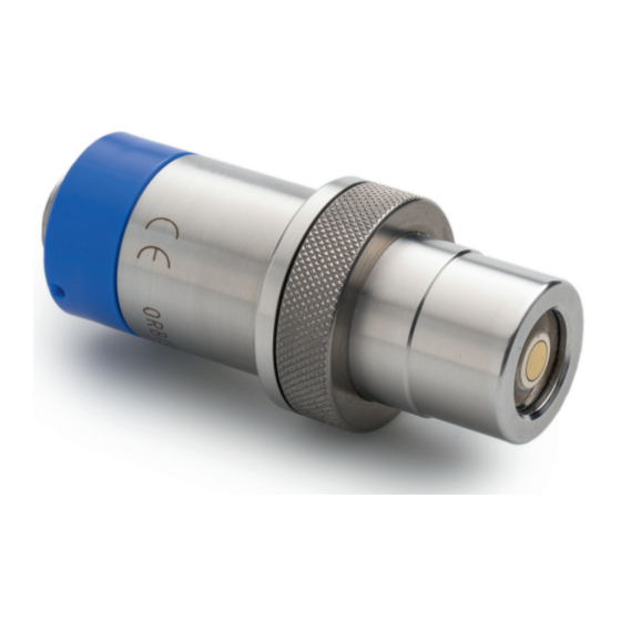
Figure 3 Product components 1 Sensor 3 Sensor recharge kit 2 Protection caps 2.3.1 Electrochemical sensor The sensor may be delivered separately or as part of an ORBISPHERE system, depending on the individual order. The sensor will be delivered fitted with a plastic screw-on storage cap to protect the sensor head. This is held in place with a plastic collar. -
Page 12: Section 3 Installation
being used once. Refer to the documentattion supplied with the recharge kit for instructions on how to use the anode cleaning tool for a GA2X00 sensor or for a A110X sensor. The cotton washers provide additional protection against the formation of deposits and residue on the center electrode and anode, which prolongs the time period required between sensor maintenance. - Page 13 1. Hold the main body of the sensor and unscrew the protection cap locking washer by turning counter-clockwise. Remove it from the sensor and put to one side. 2. Pull/twist off the protection cap and put to one side. 3. Hold the sensor with the membrane facing down to avoid spilling any electrolyte, then carefully unscrew the shipment cartridge.
- Page 14 7. Hold the container steady between thumb and forefinger of one hand. Lower the sensor into the container until the top of the anode is covered with electrolyte. Leave for a few seconds to ensure the cotton washer has fully absorbed some of the electrolyte and that it is no longer dry. 8.
-
Page 15: Sensor Installation
10. Rinse the sensor under a tap for about 5 seconds to remove any excess electrolyte, then gently wipe with a soft tissue to ensure all parts are completely dry. Drain the overflow electrolyte from the container into a sink and flush away. Discard the used container. ®... -
Page 16: Sensor Insertion
Note: There may be situations where not all the above conditions can be met. If this is the case, or you have any concerns, please consult your Hach representative to appraise the situation and define the best applicable solution. 3.2.2 Sensor insertion Note: Check that the small O-ring at the bottom of the flow chamber is present during removal and installation of the sensor, as it may stick to the sensor head and fall. -
Page 17: Accessories Installation
3.3 Accessories installation 3.3.1 External pressure sensor The system can be fitted with an external pressure sensor. This enables a measurement of fraction of gas under variable pressure conditions during gas phase measurement. Note: Do NOT exceed the pressure range of the sensor. This would permanently deform the sensor membrane, thus delivering incorrect pressure values in the future. -
Page 18: The 32003 Insertion/Extraction Valve
Figure 6 Weld-on sensor socket 1 Pipe diameter 2 Setback allowed from internal pipe diameter Figure 7 Installation in-line 1 Shut off valve 4 Shut off valve 2 Sensor socket 5 Sampling valve 3 Sampling valve 3.3.3 The 32003 insertion/extraction valve The ORBISPHERE 32003 insertion/extraction valve allows for sensor removal and installation without having to drain the fluid in the line. -
Page 19: The 33095 Sensor Housing
Figure 8 ORBISPHERE model 32003 insertion/extraction valve 1 Sensor 3 Sample flow 2 Valve 3.3.4 The 33095 sensor housing The ORBISPHERE 33095 sensor housing is also available for use with the GA2X00 sensor but requires that the sample flow be turned off prior to insertion or removal of the sensor. Sensor insertion is made by inserting the sensor into the housing and tightening the retaining collar until it stops. -
Page 20: Orbisphere Flow Chambers
3.3.6 ORBISPHERE flow chambers The ORBISPHERE 32001.xxx flow chambers are used to draw liquid and gaseous samples past the sensor. They are available in several materials, depending on the application. Refer to Table 7 Figure ™ They connect to 6-mm or ¼" stainless steel tubing by means of two Swagelok fittings. -
Page 21: Multi-Parameter Flow Chamber
Figure 11 Flow chamber connections 1 Measuring 7 Sample flow out 2 Calibration 8 Calibration gas in 3 Sensor 9 Calibration gas out 4 Calibration gas in shut off 10 Sample flow in shut off 5 Calibration gas out shut off 11 Sample flow out shut off 6 Sample flow in 3.3.7 Multi-parameter flow chamber... -
Page 22: Section 4 Maintenance
Figure 12 Multi-parameter flow chamber Shown here with: • gas sensor (right), • pressure sensor (center), • optional second sensor (left) Section 4 Maintenance W A R N I N G Multiple hazards. Only qualified personnel must conduct the tasks described in this section of the document. -
Page 23: Maintenance Schedule
4.1 Maintenance schedule The following table shows the recommended schedule for membrane replacement. The table should only be used as a guideline, as maintenance intervals will vary depending on a number of different parameters (e.g. water chemistry, CIP frequency, oxygen levels, sample temperature, etc.). Application Membrane type Membrane replacement... -
Page 24: Membrane Replacement And Sensor Head Cleaning
4.3 Membrane replacement and sensor head cleaning C A U T I O N Chemical exposure hazard. Obey laboratory safety procedures and wear all of the personal protective equipment appropriate to the chemicals that are handled. Refer to the current safety data sheets (MSDS/SDS) for safety protocols. - Page 25 7. Rinse the sensor head under a tap for 15 seconds, aiming the jet of water directly onto the sensor head. Do not dry the center electrode area, as the gap between cathode and guard should be left filled with water. 8.
- Page 26 11. Remove the polishing tool from the sensor. Remove any polish deposits by rinsing the sensor head under a tap for 30 seconds, aiming the jet of water directly onto the sensor head. Note: If the sensor is used in high level hydrogen sample, do not perform the following steps but continue at step 19.
- Page 27 16. On the sensor cleaning and regeneration center, turn the knob to the Guard position and press the TIMER switch. Again, watch for the formation of bubbles and repeat the cleaning process if necessary. 17. On the sensor cleaning and regeneration center, turn the knob to the Cathode position and press the TIMER switch.
- Page 28 20. Take a silicone disc from the recharge kit, hold it between thumb and forefinger and position it on top of the anode. Take a new cotton washer from the recharge kit. Hold it between thumb and forefinger and position it on top of the silicone disc. Note: During this step, it is very important to ensure your finger does not come into contact with the cathode (golden surface) as it could leave greasy deposits on the surface.
- Page 29 25. Rinse the sensor under a tap for about 5 seconds to remove any excess electrolyte, then gently wipe with a soft tissue to ensure all parts are completely dry. Drain the overflow electrolyte from the container into a sink and flush away. Discard the used container. ®...
-
Page 30: Section 5 Troubleshooting
Section 5 Troubleshooting 5.1 Oxygen sensor Problem Probable cause Possible solution Sensor won't calibrate, even after Instrument internal Calibrate using a certified barometer. Do not cleaning and/or membrane barometric pressure correct for sea level ! change. sensor needs calibration. Wet membrane Wipe dry with a tissue and re-calibrate. -
Page 31: Section 6 Replacement Parts And Accessories
Problem Probable cause Possible solution Calibration is out of specification Sensor incorrectly setup. Check the sensor parameters on the instrument. or response time is too slow. Re-calibrate the sensor. Temperature Control the temperature with an external measurement incorrect. reference. Re-calibrate the sensor. Barometric pressure Calibrate the barometric pressure sensor using incorrect. - Page 32 Flow chambers and installation devices (continued) Description Item no. Flow chamber in Monel with 6 mm fittings. Supplied with EPDM O-rings. 32001.070 Flow chamber in Monel with ¼" fittings. Supplied with EPDM O-rings. 32001.071 Flow chamber in stainless steel (316) with 6 mm fittings. Supplied with Viton O-rings. 32001.110 Flow chamber in stainless steel (316) with ¼"...
- Page 33 Sensor replacement parts (continued) Description Item no. GA2800 oxygen sensor, ATEX, hastelloy, kalrez o-rings, cap without grille GA280E-HKS Stainless steel sensor collar 28104 PPS sensor collar 28105 Delrin storage cap (sensor storage cap) 28129 Sensor support (base) for 31xxx, X110X and GA2X00 sensors 32205 Stainless steel 28mm cap for ORBISPHERE GA2X00 family EC sensors (without 33051-S0...
- Page 34 Recharge kits (continued) Description Item no. For 6110 TPA. Recharge kit of 4 pre-filled cartridges with premounted 2956A membranes for A1xxx and GA2x00 oxygen sensors. Includes o-rings, cotton washers, 2956A-AT silicone discs and cleaning tools For 6110 TPA. Recharge kit of 4 pre-filled cartridges with premounted 2956A membranes for A1xxx and GA2x00 oxygen sensors.
- Page 36 Tel. +49 (0) 2 11 52 88-320 SWITZERLAND Fax (970) 669-2932 Fax +49 (0) 2 11 52 88-210 Tel. +41 22 594 6400 orders@hach.com info-de@hach.com Fax +41 22 594 6499 www.hach.com www.de.hach.com © Hach Company/Hach Lange GmbH, 2019. All rights reserved.