Table of Contents
Advertisement
Quick Links
Advertisement
Table of Contents

Related Manuals for Yamaha SU700


Summary of Contents for Yamaha SU700
- Page 1 SAMPLING UNIT Owner's Manual...
-
Page 2: Important Safety Instructions
Some of these items are de- signed to be dealer assembled or installed. Please make sure that benches are stable and any optional fixtures (where applicable) are well secured BEFORE using. Benches supplied by Yamaha are designed for seating only. No other uses are recommended. - Page 3 SPECIFICATIONS SUBJECT TO CHANGE: The information contained in this manual is believed to be correct at the time of printing. However, Yamaha reserves the right to change or modify any of the specifications without notice or obligation to update existing units.
- Page 4 • Always save data to a floppy disk frequently, in order to help prevent the loss of important data due to a malfunction or user operating error. Yamaha cannot be held responsible for damage caused by improper use or modifications to the instrument, or data that is lost or destroyed.
- Page 5 This manual will help you learn what you need to know to make effec- tive use of all of the SU700’s many features. Please read through the essential parts of the manual carefully before beginning work with the SU700, and refer back to the manual for additional information as necessary.
-
Page 6: Features
Features The SU700 is an ideal tool for artists in need of sampling and sequencing capabilities for their recording and performance work. Here is just an abbreviated list of what’s included. Forty-two tracks. With 40 sample tracks plus 2 special tracks, you can make your songs as complex as you wish. -
Page 7: Accessories
Accessories Please check your SU700 package to confirm that all of the following accessories are present. If any items are missing or damaged, please contact your Yamaha dealer for assistance. Sampling CD “SU700 Sampling Audio” Demo floppy disk Power cord This Owner’s Manual... - Page 8 Chapter 3: Basic Concepts, Track Types, and Memory Introduces basic concepts underlying SU700 operation. Also provides a detailed ex- planation of the different track types, and explains how the SU700 memory is orga- nized. You should read through this chapter before you begin serious work with the SU700.
-
Page 9: Notations
Appendix 1 provides detailed instructions for installing each of the SU700’s sup- ported options. Appendix 2 gives the SU700 specifications. Appendix 3 offers a number of helpful usage tips. Appendix 4 explains the SU700 error messages. Ap- pendix 5 lists and describes the 43 built-in effects and their associated parameters. - Page 10 Finally, please note that screen illustrations and other drawings presented in this manual are for explanatory purposes only, and in some cases may differ from actual displays and configurations. Intro...
-
Page 11: Table Of Contents
Table of Contents Intro Yamaha SU700 Sampling Unit Owner’s Manual Features ... 6 Accessories ... 7 Using the Manual ... 7 Notations ... 9 Chapter 1 SU700 Components, Connections, and Startup SU700 Layout ... 14 SU700 Display Configuration ... 23 Connecting Up ... - Page 12 10.2 General Procedure ... 225 10.3 Job Explanations ... 227 Appendix Installing the Options ... 312 Specifications ... 326 SU700 Usage Hints ... 328 Error Messages ... 331 Effect Type List ... 333 Effect Parameter List ... 335 MIDI Data Format ... 345 MIDI Implementation Chart ...
-
Page 13: Chapter 1 Su700 Components, Connections, And Startup
Chapter 1 SU700 Components, This chapter describes the SU700’s layout and screen displays, shows you how you can connect the SU700 to other devices, and takes you through the SU700 startup procedure. Chapter 1 SU700 Components, Connections, and Startup Connections, and Startup 1.1 SU700 Layout... -
Page 14: Su700 Layout
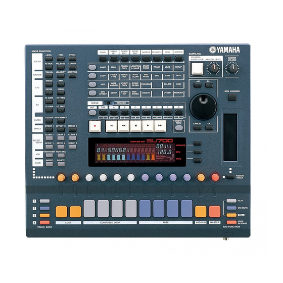
This section explains all of the SU700 components. 1.1.1 Main Panel 1 Display The display provides all the information you need to work effectively at the SU700. For a detailed explanation of common screen displays and indications, see page 23. Chapter 1 SU700 Components, Connections, and Startup... - Page 15 You use the track bank selectors in combination with the sample track pads to se- lect tracks for playback, recording, editing, and control. The SU700 provides four track banks, each with ten sample tracks. This gives you a total of 40 sample tracks. This means that each song can utilize anywhere from 1 to 40 samples.
- Page 16 You can set the ribbon up to control a single selected function with respect to a single pad. You select the track set using the [RIBBON TRACK] button; see be- low. Chapter 1 SU700 Components, Connections, and Startup , etc.). , and...
- Page 17 D Dial Use this dial to enter and adjust various values. Actual operation varies according to the SU700’s current state. The value that can be adjusted by the dial is usually shown in blinking format on the display. E [BPM COUNTER] button This button makes it easy to set the tempo to match the tempo of external play- back that you may be preparing to record or play along with.
- Page 18 Hold down to move rapidly forward through the song. L Job Grid You use these buttons to access various SU700 jobs. These jobs let you carry out a wide variety of editing, setup, and management tasks. To select a job, you first press one of the job group selectors along the top of the grid, and then press one of the job selectors along the left of the grid.
- Page 19 For de- tailed information, see Chapter 9, page 213. Chapter 1 SU700 Components, Connections, and Startup p.180)
-
Page 20: Front Panel
Do not eject the disk while the access lamp is lit. 3 Floppy Access Lamp This lamp lights up to indicate that the SU700 is currently accessing the disk. CAUTION Do not press the EJECT button or switch off the power while this lamp is lit, as doing so may destroy data on the disk or cause damage to the disk drive. -
Page 21: Rear Panel
1 STEREO OUT Jacks These jacks output the stereo analog signal produced by the SU700 to powered speakers or other playback device. (For monaural output, use the left jack only.) These are the standard outputs. - Page 22 Each connector can support both mono and stereo signals. Input Signal: The SU700 can accept input digital frequencies of 11.025kHz, 22.05kHz, 32.0kHz, 44.1kHz, and 48.0kHz. (If you wish to enable this input, you must open the SYSTEM | SETUP job and set AU- DIO IN to either OPTICAL or DIGITAL.
-
Page 23: Su700 Display Configuration
1.2 SU700 Display Configuration You refer to the SU700 screen for information and guidance during all SU700 opera- tions. This section presents an overview of the various screen displays. The first part, “Screen Layout,” introduces the various elements of the display panel. - Page 24 7 BPM ... Shows the current tempo (in beats per minute). 8 NOTE ... Shows the quantize interval or time resolution, when ap- Chapter 1 SU700 Components, Connections, and Startup screen, each vertical bar meter (or track meter) indicates the relevant knob-function value for the corresponding track (of the current bank).
- Page 25 ATTACK, all meters change to indicate ATTACK levels. • Brackets are visible if track is non-muted; invisible if track is muted. 4 Current position in song. 5 Tempo setting. 6 The NOTE area is always empty. Chapter 1 SU700 Components, Connections, and Startup p.142) p.231). This means...
- Page 26 If the track is empty, then no bar will appear. The following shows the display you use to select the track when preparing to record a sample. Chapter 1 SU700 Components, Connections, and Startup to set the sequencer into RECORD mode.
- Page 27 The following shows how the screen may appear when you are standing by to begin sample recording. 1 Shows the recording parameters. 2 Monitors the left-channel input level. 3 Monitors the right-channel input level. 4 Shows the destination track. 5 CLIP indicator Chapter 1 SU700 Components, Connections, and Startup Sample plus sequence data:...
- Page 28 Ribbon-Track Indication When you press the [RIBBON TRACK] button, the brackets for the currently se- lected ribbon track blink on the screen. You can change the selection by pressing a different pad. ( p.172) Chapter 1 SU700 Components, Connections, and Startup...
-
Page 29: Connecting Up
1.3 Connecting Up The SU700 is extremely easy to set up. Simply connect the appropriate components as described below. Power Connect the power as follows. Confirm that the power switch (on the rear panel) is in the OFF position (pro- truding from the panel). - Page 30 To enable input, you must set the AUDIO IN parameter to the source you wish to use. You can set the parameter using the SYSTEM | SETUP job; see page 302. The SU700 can only accept input from one source at a time. Record (turntable) Microphone...
- Page 31 (a) The track is directed to the selected jack(s) only. It does not flow to the STEREO OUT or digital/optical outputs. (b) The track output does not pass through the effect blocks. For information about setting up the OUTPUT TO parameter, see page 239. Chapter 1 SU700 Components, Connections, and Startup ANALOG INPUT...
- Page 32 MIDI cable from the SU700’s MIDI OUT connector to the MIDI IN connector on the target device. Note that you must use the SYSTEM | MIDI jobs to set up the SU700’s MIDI opera- tion ( p.303).
-
Page 33: Starting Up
NOTE: Auto-loading does not work with volumes that span multiple disks. If you want to load a volume from multiple disks, you must start the SU700 first and then use the DISK | LOAD/ LOAD VOLUME job ( Press the power switch on the rear panel so that it engages in the ON position. - Page 34 Chapter 1 SU700 Components, Connections, and Startup...
-
Page 35: Chapter 2 Tutorial
Chapter 2 Tutorial This chapter takes you through a tutorial that will give you some quick hands-on experience with the SU700. The first part of the tutorial how to play the demo song and how to use various features. The second part of the tutorial takes you through the procedures for recording samples and building a song. -
Page 36: Setting Up
CD. Connections Before you make connections, be sure that the power of the SU700, your CD player, and your audio system is turned off. Connect the analog outputs from your CD player to the ANALOG INPUT jacks on the rear of the SU700. -
Page 37: Listening To The Demo Song
SU700 will automatically load the demo song. CAUTION If you load the demo song after using the SU700, all data currently in internal memory will be lost. If memory contains any data you wish to keep, be sure to save it to disk etc. (Save: p.287) before you load the demo song. - Page 38 “LOADING …” Do not eject the floppy disk or switch off the SU700 power while the word LOAD- ING... is on the display, as doing so may cause damage to the disk or the disk drive.
- Page 39 Indicates the currently selected bank. Song number Indicates the song number of the currently selected song. (The SU700 stores up to 20 songs, each identified by a number.) Song name Name of the currently selected song. (Each song takes a name of up to eight alphanumeric characters.)
- Page 40 You can use the [BPM COUNTER] button to tap out the tempo that you want to use. The SU700 automatically detects the tempo and displays it in the BPM area. If you wish to use the newly displayed tempo, press [OK]. (If you don’t press OK within sev- eral seconds, the old tempo value will reappear.) (...
- Page 41 When the song data is played back to a location where Track Mute on/off data was written, the mute settings you made manually will change. Using the ROLL Pad Function The roll function generates a drum-roll (machine-gun) type of sound by rapidly re- peating the first part of the sample.
- Page 42 Using the LOOP START Pad Function You can use this feature to restart the loop on any of the LOOP or COMPOSED LOOP tracks. Press the [LOOP RESTART] pad-function button. The upper part of the display will indicate “LOOP RESTART.” With the song playing, try pressing the pad on any (un-muted) LOOP or COM- POSED LOOP track that you wish to restart.
- Page 43 Now press the [PLAY] pad-function button, so that pads can be used to play the samples. Now you can use the pads to play the samples. Try pressing the pad for each track to hear the sample. By doing this you can identify all of the song’s samples and the tracks they are located on.
- Page 44 To adjust the level on any track, turn the track’s knob. You can listen to the re- sult by hitting the track’s pad. Rotate the knob for the LOOP1 track to adjust Adjusting the Other Parameters Now try adjusting some of the other parameters in the same way. First press the but- ton on the Knob Function panel, and then turn the knobs on each track while at the same time hitting the pad so that you can hear the sound.
- Page 45 Using the Ribbon Controller You can use the ribbon controller to control any one of the knob settings, or else to control a special scratch function. The ribbon controller (or just ribbon) works on only one selected track at a time. (For details about ribbon setup, see page 172.) Trying Out the Scratch Function Under factory defaults, the ribbon is set to control the scratch function.
- Page 46 NOTE: To provide this function, the SU700 maps the sample to the ribbon, with the start point of the sample mapped to the bottom of the ribbon. Each point on the ribbon corresponds to a specific location on the sample waveform. For more information, see page 173.
-
Page 47: Building Your Own Song
A finished version of the song we will be creating is provided on the included audio CD “SU700 Sampling Audio” (Track 93). You may want to listen the song on your CD player so that you can hear the type of sound we are trying to create. - Page 48 Our song will use all of the tracks in bank 1 plus FREE tracks 1–4 of bank 2, for a total of fourteen tracks. Tracks 79–92 of the included audio CD (SU700 Sampling Audio) contain the sample sources that we will use for this tutorial. First let’s sample these sources and use them to create a song.
- Page 49 We’ll use these tracks to play sound effects, drums, and fills at various locations throughout the song. We’ll also use the ribbon controller to scratch out these sounds during the Intro and Ending sections. As with the sample on FREE 1, we’ll set the sound up in two different ways for track banks 1 and 2, so we can get different sounds in different sections.
- Page 50 One way is to eject the floppy from the slot (press the EJECT button just under the slot) and then switch the SU700 power off and back on. Another way is to delete the song using the SONG | INIT job ( 2.3.1 Setting Up The First LOOP Track (“LOOP 1”)
- Page 51 Now turn the dial as necessary so that the screen says AUDIO IN. Then press [OK]. Then turn the dial again (if necessary) so that the screen says AUDIO IN=LINE. Then press [OK] once more. With this setting, the included audio CD can be used as a source for sampling. NOTE: You can also supply sound through a microphone connected to the ANALOG IN input(s), provided that you first set ANALOG INPUT to MIC .
- Page 52 Sampling frequency. Let’s leave the frequency at 44K and the resolution at 16BIT, but let’s change the format to “MONO L” (so that the SU700 will record a monaural sample from the left channel of the stereo CD). Bit resolution...
- Page 53 Now let’s adjust the input level from the CD. First, start playback of track 79 on the sampling CD. If the CD player is correctly connected to the SU700, you will hear the sound com- ing through the SU700 and you will see the level meter moving on the screen. Note that the meter grows to the right as the level increases;...
- Page 54 CANNOT FIND LOOP message. In this case you must press either [CAN- CEL] or [OK] to escape: the SU700 will discard the recorded data and return you to the main screen. If the track already held a sample, that sample is retained.
- Page 55 When you select the same track as the recording destination, the SU700 will display the query REPLACE? , asking you whether you wish to replace the data that you have already recorded. Simply press [OK] to proceed.
- Page 56 Next, press the top job selector if you wish to adjust the start point, or the second job selector if you wish to adjust the end point. You can move back and forth between the two adjustments as necessary by pressing these two buttons. Then press here or here to move to start-point or end- point adjustment screen.
- Page 57 2.3.2 Setting Up LOOP 2 Recording the Sample Using the same procedure as we did for the LOOP 1 track, we will now sample Track 80 (bass phrase) from the included audio CD to the LOOP 2 track. Procedure Press the [SAMPLING] button to enter sample-recording mode. The screen displays the [SELECT TRACK] message.
- Page 58 NOTE: You can also listen to the both loop tracks together by starting the sequencer (by pressing ).You may want to try this to get an idea of how the loops sound when playing to- gether. But remember that you must stop the sequencer before you can proceed to edit the sample length.
- Page 59 008 for LOOP 2, and a BPM value in the region of 172 for both. Alternatively, the SU700 may have detected a LOOP LENGTH of 002 for LOOP 1 and 004 for LOOP 2, with a BPM in the region of 86 for both. In this latter case, you will need to set the LOOP LENGTH manually to the correct value.
- Page 60 Adjusting the groove When you listen to LOOP 1 (drums) and LOOP 2 (bass) together, the groove may not match precisely. There are several possible reasons. Loop point connections If the loop points of the sample do not coincide with beats, the groove will not feel right.
- Page 61 Press the sequencer and use the dial to try various note value settings. Notice how the groove changes. For this example, let’s set this parameter to an 8th note ( Aligning the left and right channels of a stereo sample In the case of a stereo sample, skewed timing between the left and right channels may impair the groove.
- Page 62 When the metronome is turned on, you can choose whether re- cording begins immediately (when you engage REC mode) or whether the SU700 will produce a click sound as a 1-measure or 2-measure lead-in. The factory default is a 2-measure lead-in.
- Page 63 NOTE NOTE: • When recording your input actions, the SU700 automatically adjusts the timing of pad actions and certain knob actions in accordance with you QUANTIZE setting. Since we have set quantize to quarter-note, the SU700 will automatically move all of the quantizable input actions to the nearest quarter-note interval (the nearest beat).
- Page 64 NOTE: • Be aware that the SU700 quantizes the pad-press event (note-on event), but does not quantize the pad-release event (note-off event). Provided that you hit the pad within a one-eighth note interval on either side of 003:1, the SU700 will record the note-on event at 003:1 exactly.
- Page 65 Undo is valid only for the immediately-previous recording operation (stop cording stop). When you perform the next recording operation (stop stop), it will not be possible to Undo any prior recording operations. Redo To delete a sample that was recorded by mistake Put the sequencer in recording mode ( you wish to delete is played, hold down the JOB group [NOTE DEL] button and press the CL1 pad to delete any note-on data for the CL1 sample that occurs in that...
- Page 66 Tips for recording If the tempo is too fast for you to achieve accurate timing, use the dial to lower the BPM setting and try recording at a slower tempo. You can press the [MEASURE] button, use the dial to move to the desired mea- sure location, and begin recording from there.
- Page 67 Use the cursor buttons ( tate the dial to set it to “1,” and press the [OK] button. If there is more than one note event, use the next event, or In addition to the location of a note event, you can also modify its velocity and gate time.
- Page 68 2.3.5 Setting Up The Third COMPOSED LOOP track (“CL3”) Sampling Using the same procedure as you did for the LOOP 1 track, sample Track 83 of the included audio CD to the COMPOSED LOOP 3 track (hereafter referred to as “CL3”). Set the sampling grade to “22K 8BIT MONO L.”...
- Page 69 Recording the Loop Phrase Now we’ll record the sample to the CL4 track of the sequencer. The CL4 track is a loop 32 quarter-notes long (eight measures), and will play the sample starting at the first beat of measure 3 and extending for four beats. Record this phrase using the same method you used to record on the other CL tracks.
- Page 70 For each sample, set the sampling grade to “22K 8BIT MONO L.” The sampling procedure is the same as for the LOOP 1 track. ( When sampling to track bank 1, press the TRACK BANK button [1] before selecting the sampling track (the “SELECT TRACK” display). When sampling to track bank 2, press the TRACK BANK button [2].
- Page 71 If you wish to adjust the overall sound, turn the knob on the MASTER track. NOTE: • You can also adjust the overall sound using the MASTER VOLUME knob. But the MASTER-track setting can be stored into a scene and reproduced each time you play the song.
- Page 72 2.3.10 Putting the Song Together Now we’ll build a song using the samples we have recorded into our ten sample tracks in bank 1. The song will consist of ten sections, as outlined on page 49 and again below. For each section we will use a different muting arrangement.
- Page 73 Song Transition Structure We will assign the following content to each of the eight scene buttons, which corre- spond with places where the track mute settings change during the song. (For details on the structure of this song, see page 49.) Track Mutes *1 Measure Section...
- Page 74 Storing the mute settings of each block to a scene button Let’s store the mute settings of the tracks for each song block to a scene button. Intro A = scene button [TOP] Ending B = scene button [G] Intro A and Ending B have the same mute settings. We will defeat muting only for the FREE 1–4 tracks of track bank [2], and mute all the other tracks.
- Page 75 Press the PAD FUNCTION [PLAY] button. This completes mute settings. Now we will store this condition to the [TOP] and [G] scene buttons. Set the [SCENE/MARKER] switch to the SCENE position. Continue pressing the [TOP] button until the display indicates “SCENE STORED.” set to the SCENE position Release the [TOP] button.
- Page 76 Procedure Press the PAD FUNCTION [ON/MUTE] button. We will start with the settings of the [TOP] and [G] scenes, and un-mute the CL1/2 tracks of track bank [1]. Press the TRACK BANK [1] button to select track bank [1]. Then press the pads of CL1/2 tracks to make the bracket ( Press the PAD FUNCTION [PLAY] button.
- Page 77 Section C = scene button [E] Un-mute CL 1–4 tracks of track bank [1] and FREE 1–4 tracks of track bank [2] so that they will be heard. TRACK LOOP C.LOOP BANK 1 2 3 4 Section D = scene button [F] Un-mute CL3/4 tracks of track bank [1] and FREE 1–4 tracks of track bank [2] so that they will be heard.
- Page 78 Watch the location indicator. You now want to press and release the Scene [A] but- ton, timing your action so that you release the button as the song location is chang- ing from 008:4 to 009:1. Then press scene buttons to record the remaining scene changes at the measure lo- cations shown below.
- Page 79 Press to stop the sequencer. Then press nally, press to listen to the result. As playback proceeds, you should see and hear the mute settings and the FREE-track setup (the samples that are played by the FREE 1–4 track pads) change as you move from one section to another. NOTE: •...
- Page 80 2.3.11 Recording the FREE Tracks Now that we’ve set up the basic structure for our song, we’ll proceed to record note and ribbon events onto our FREE tracks. This is the final step in the building of our song. NOTE: •...
- Page 81 The number of lead-in measures is determined by the COUNTDOWN parameter in the SYSTEM | SETUP job ( p.299). It is assumed that the SU700 is currently set to give you two lead-in measures (since this is the factory default).
- Page 82 Turn the dial until the screen indicates that the function is set to SCRATCH, and press [OK]. Now let’s assign the ribbon so that it works with the second FREE track (FREE 2). To do this, hold down the [RIBBON TRACK] button and press and release the FREE 2 pad.
- Page 83 Building Sections A and B Now we will record FREE tracks 1–4 of track bank 1 for sections A and B. We will play the sample on FREE track 1 at the beginning of each section. For the other FREE tracks (FREE 2, 3, 4), you can strike pads to record notes (pad presses) at any locations you like while listening to the playback from the other tracks.
- Page 84 Recording on Other Free Tracks (FREE 2, 3, and 4) Put the sequencer in recording mode, and press the pads for FREE tracks 2/3/4 at the locations shown in the table below. MEASURE Section A 025:1 028:1 032:1 032:4 036:1 040:1 040:4 Section B...
- Page 85 Building Section E Section E is simply two repetitions of Section B (16 measures). Record section E in the same way that you did for Section B. Record each track as shown in the following table. FREE Tracks MEASURE 073:1 076:1 080:1 080:4...
- Page 86 In the same way as for [LEVEL] settings, the parameters set by the KNOB FUNC- TION buttons can be modified and stored again to a scene button. When the song is played back, the modified settings will be recalled. Detailed adjustments to note events can be made using the Event Edit function “LOCATION &...
- Page 87 Use the same procedure to finish entering the name. Then press [OK] to register the song name and return to the main screen. (Or press [CANCEL] at any time to restore the original name and return to the main screen.) The main screen will show the song name that you specified.
- Page 88 2.3.14 Saving the Song The SU700 loses all song data when you switch off the power. So let’s save the song to floppy disk. To save a song, you must execute a volume save. This will write all existing song data (all songs currently in SU700 internal memory) to disk.
- Page 89 Press [OK] to execute the save. While the data is being saved, the display will indi- cate “SAVING…” You cannot use [CANCEL] to stop the operation while the SU700 is writing to disk. If the volume is too large to fit on a single floppy, the screen will display a slightly different message: SAVING...
- Page 90 CAUTION When a volume is loaded, all data currently in the SU700 will be lost. Be sure that any important data has been saved to disk before you execute the load operation.
- Page 91 The following display will appear, allowing you to confirm that the load source drive is the floppy disk drive. If a SCSI drive is connected, use the dial to select “FDD.” Press the [OK] button, and the load source volume select display will appear. Since a floppy disk can contain only one volume, that volume name will be displayed.
- Page 92 2.3.16 Techniques for song playback By taking advantage of various techniques as you playback a song, you can add vari- ety to the performance. Using the function knobs When you press a KNOB FUNCTION button, the knobs of all tracks will perform the specified function.
- Page 93 The SU700 can be synchronized with an external MIDI device. An external MIDI se- quencer synchronized with a SU700 song can be used to play the melody, or you can play SU700 samples along with the playback of an external MIDI device.
- Page 94 When a song is played back, the NOTE area of the display may indicate “QUAN- TIZE” or “RESOLUTION,” depending on the selected knob function or pad function. By setting “QUANTIZE,” you can correct the timing at which a sample is played. (The accuracy is specified as a note value.) “RESOLUTION”...
-
Page 95: Modifying Sampled Sounds
Our song will use ten samples—thereby making use of all tracks in Bank 1. All tracks will use samples recorded from the included sampling CD (SU700 Sampling Audio). Using the procedure described in “Building Your Own Song,” go ahead and sample these unprocessed sources (tracks 79–92). - Page 96 COMPOSED LOOP 4: ... Source: Track 45-13 (*Radiator) We’ll build an eight-measure effect-type phrase. We’ll drop the pitch of the origi- nal sample, and apply LFO modulation, filtering, and effects. FREE 1: ... Source: Track 64-1 (*Japaneez Rev) We’ll use a long sample, with a duration of at least four measures (16 beats). We’ll set the sound up in two different ways, and use the different sounds in different sections of the song.
- Page 97 Song structure The song will be structured in the same ten blocks as in the previous section, “Build- ing Your Own Song.” In the following table, the material printed in bold indicates the differences from the song you created in “Building Your Own Song.” Measure Section Intro A...
- Page 98 Before you sample! Make sure that you have sufficient memory before you begin sampling. If you have loaded the demo song or created a song as described in the previous section, turn the power off and then on again to clear the memory before you begin creating the song described below.
- Page 99 Procedure Press the EFFECT/[EFFECT 1] button. The effect type “AMP SIM” that is assigned to EFFECT 1 will be displayed. Since the amp simulator effect is a system effect ( independently adjust the depth of the effect for each track. Use the LOOP 1 track knob to set “AMP SIM=040.”...
- Page 100 Equalizer (EQ) settings Next we will use the EQ/[LO GAIN] button to raise the level of the low-frequency re- gion. Procedure Press the EQ/[LO GAIN] button. The display will indicate “EQ LO GAIN = +00.” Rotate the LOOP 1 track knob to make the display read “EQ LO GAIN = +24.”...
- Page 101 Rotate the LOOP 2 track knob to make the display read “PITCH =+003.” Filter resonance settings We will raise the filter resonance to emphasize the overtones of the sound. Procedure Press the FILTER/[RESONANCE] button. Rotate the LOOP 2 track knob to make the display read “RESONANCE=000.” 2.4.2 Creating the LOOP 2 track Sampling We will sample track 77-5 “Jumping Jaks”...
- Page 102 Track editing (creating a loop phrase) The LOOP 2 track is a loop that plays back endlessly, as is the LOOP 1 track. We will adjust the start/end point of the sample to create a loop that is suitable for our song. The loop phrase editing procedure is the same as described on page 55 of “Build- ing Your Own Song.”...
- Page 103 In the FILTER group of the knob function buttons, press the [CUTOFF] button, and ro- tate the LOOP 2 track knob to make the display read “FILTER CUTOFF=024.” Next press the FILTER/[RESONANCE] button, and rotate the LOOP 2 track knob to make the display read “RESONANCE=050.”...
- Page 104 Pitch settings Since we want to use the sample of the LOOP 2 track to play the bass, we will lower its pitch. Procedure Press the SOUND/[PITCH] button. Rotate the LOOP 2 track knob to make the display read “PITCH=-045” At the location where you want to audition the sound, press the sequencer and listen to the LOOP 1 and LOOP 2 tracks.
- Page 105 Rotate the dial to select “LOOP LENGTH,” and press the [OK] button. The current loop length (which was set automatically) will be displayed. Rotate the dial to make the display read “LOOP LENGTH=008,” and press the [OK] button. BPM setting Press the sequencer button, and while you listen to check that LOOP 1 (drums) and LOOP 2 (bass) are suitably synchronized, set the BPM.
- Page 106 2.4.3 Creating the COMPOSED LOOP 1 track Sampling We will sample track 75-1“Lo Note Rezo C2” from the included audio CD to the COMPOSED LOOP 1 track (subsequently referred to as CL1). The sampling procedure is the same as described on page 50 of the preceding sec- tion, “Building Your Own Song.”...
- Page 107 The display will indicate the effect type that is currently selected for EFFECT 2. This will be “1DELAY.” Since “1DELAY” is a system effect ( meter area for all tracks. Each effect has several parameters which adjust some aspect of the effect. By modi- fying the parameter settings, you can change the speed or depth etc.
- Page 108 Turn the knob for track CL1 to make the display read “1DELAY=020.” Now let’s set the delay interval of 1DELAY to match the BPM of the song. Press the [NOTE] button to that “RESOLUTION=” is blinking. Then turn the dial to select a note value of Loop length setting Using the same procedure as you did for LOOP 2, set the sample loop length of the...
- Page 109 Procedure Press the sequencer button to enter record-ready mode. Press the [NOTE] button, and turn the dial to set Quantize to a quarter note ( Press the sequencer (MEASURE display 003:1), press and hold the CL1 pad for five beats. Release the pad immediately before you reach 004.2.
- Page 110 Modifying the sound For the CL2 track, only the pitch will be different. [Settings] SOUND group ... [PITCH] Use the same procedure as for the LOOP 1 and 2 tracks to make settings. Loop length setting Using the same procedure as when you set the LOOP 2 track, set the sample loop length of the CL2 track to “LOOP LENGTH=016.”...
- Page 111 2.4.5 Creating the COMPOSED LOOP 3 track Sampling We will sample track 45-1 “*Harp Gliss Down” from the included audio CD to the COMPOSED LOOP 3 track (subsequently referred to as CL3). The sampling procedure is the same as described on page 47 of the preceding sec- tion, “Building Your Own Song.”...
- Page 112 Begin recording using the same procedure as for the CL1 track, and at the first beat of the first measure (MEASURE display 001:1), press and hold the CL3 pad. Continue holding it for three beats, and release it immediately before 001:4. 2.4.6 Creating the COMPOSED LOOP 4 track Sampling We will sample track 45-13: “*Radiator”...
- Page 113 Recording to the sequencer Now we will record the sample for the CL4 track on the sequencer. The sample for the CL4 track will be looped over 32 quarter-note beats (eight mea- sures), and will sound for four beats from the beginning of measure 3. (See diagram below.) Begin recording using the same procedure as for the CL1 track, and at the first beat of the third measure (MEASURE display 003:1), press and hold the CL4 pad.
- Page 114 [Settings] FREE 1 track SOUND group ... [PITCH] FILTER group ... [CUTOFF] EFFECT group ... [EFFECT 1] FREE 2 track SOUND group ... [PITCH] EFFECT group ... [EFFECT 1] FREE 3 track SOUND group ... [PITCH] LFO group ... [SPEED] FILTER group ...
- Page 115 2.4.8 Track mixing Now that we have recorded all of our samples, let’s adjust the volume balance be- tween tracks. Procedure Press the PAD FUNCTION [ON/MUTE] button, and then press the MASTER track pad twice to defeat muting for all tracks. (All tracks will now be able to sound.) Press the PAD FUNCTION [PLAY] button, and then press the SOUND/[LEVEL] but- ton.
- Page 116 Effect settings On the SU700, you can assign any desired effect type to each of the three buttons [EFFECT 1]-[EFFECT 3], and then specify how each of the three effects will be ap- plied to each track. Procedure Select the effect type and the depth of the effect Press the EFFECT SETUP/[SETUP 1] (or [SETUP 2] or [SETUP 3]) button.
- Page 117 Example display when a system effect (1DELAY) has been selected Indicates the depth at which the 1DELAY effect is applied to each track In the case of an Insertion effect, brackets ( display of the tracks to which the effect is connected. The effect will apply only to the sample of the tracks that you selected by pressing their pad.
- Page 118 Setting the effect parameters Each effect has several parameters that determine how it will process the sound. By modifying the parameter settings you can change the speed or depth etc. of the ef- fect. Use the cursor buttons ( and use the dial to set the value. NOTE: •...
- Page 119 Setting the effect depth and rate of change When you press an EFFECT/[EFFECT 1]-[EFFECT 3] buttons, the effect type selected for the corresponding button will be displayed. In the case of a system effect, the specified effect can be applied to all tracks. Turn the knob of the track to which you wish to apply the effect, and specify the effect depth for that track.
- Page 120 2.4.9 Song structure Now we have provided samples for the ten pads (tracks) of track bank 1. In the previous section “Building Your Own Song,” we switched between two banks to play a total of eight samples on FREE tracks 1–4. However this time, we will use only the four samples of one bank.
- Page 121 Storing settings for type A sounds in the scene buttons First we will store settings to the scene buttons for the song sections which use type A sounds on FREE tracks 1–4. Section A = scene button [C] We will mute only the CL4 and CL4 tracks, and store these settings to scene button [C].
- Page 122 For the following song sections, use the same procedure to store the mute settings to scenes. Sections B and E = scene button [D] Defeat muting on all tracks (so that they will sound), and store the settings in scene button [D].
- Page 123 LFO group... [PITCH] FILTER group ... [RESONANCE] EFFECT group ... [EFFECT 1] [EFFECT 2] [EFFECT 3] FREE 4 SOUND group... [LEVEL] [PAN] [ATTACK] LFO group... [SPEED] EQ group... [HI GAIN] [LO GAIN] [LO FREQ] FILTER group ... [RESONANCE] EFFECT group ... [EFFECT 1] [EFFECT 2] [EFFECT 3] Now let’s store the settings for song sections of FREE tracks 1–4 which use type B...
- Page 124 Section C = Scene button [E] Using the same procedure as you did for the type A sounds, mute only the LOOP tracks 1 and 2, and store the mute settings in scene button [E]. Section D = Scene button [F] Using the same procedure as you did for the type A sounds, mute LOOP tracks 1/2 and CL tracks 1/2, and store the mute settings in scene button [F].
- Page 125 NOTE: • The [UNDO/REDO] is available when recording scene changes. • To delete a scene event, you can use the Event Edit group function Location & Value. p.246) • Depending on the timing at which you recall a scene, sound may remain at the be- ginning of the measure, or the beginning of a measure may drop out.
- Page 126 2.4.10 Recording the FREE tracks Now that the overall form of the song is complete, we have come to the last step — recording the FREE tracks 1–4 on the sequencer. Recording intro A and B The FREE 1 track sample which is used in Intro A and B is a long sample that plays for more than 16 measures.
- Page 127 Recording the sections and endings You can record sections A–E and endings A and B in the same way as explained on pages 83 to 85 of “Building Your Own Song.” Refer to these pages and following, and complete your recording. When you have finished recording the FREE tracks, your song is complete! Play back the song, and adjust the overall volume balance and other final adjust-...
- Page 128 This table shows the timing of the scene changes and the timing of the pad on/off (note on/off) events for the completed version of the SU700 tutorial song that is in- cluded as track 93 of the included audio CD (SU700 Sampling Audio).
- Page 129 SCENE SCENE FREE1 FREE1 FREE2 FREE2 FREE3 FREE3 FREE4 FREE4 SCENE SCENE FREE1 FREE1 FREE2 FREE2 FREE3 FREE3 FREE4 FREE4 SCENE SCENE FREE1 FREE1 FREE2 FREE2 FREE3 FREE3 FREE4 FREE4 SCENE SCENE FREE1 FREE1 FREE2 FREE2 FREE3 FREE3 FREE4 FREE4 SCENE SCENE (TOP)
- Page 130 Chapter 2 Tutorial...
-
Page 131: Chapter 3 Basic Concepts, Track Types, And Memory
This chapter explains the relationship between songs, samples, and tracks, and introduces some important concepts required for operating the SU700 effectively. It explains the three different types of sample tracks (LOOP, COMPOSED LOOP, and FREE). Finally, it describes the SU700 memory implementation. -
Page 132: Basics
The main objective at the SU700 is to build and perform multitrack sequences called songs. The SU700 can hold up to 20 songs within its internal memory. Each song com- prises action on up to 42 tracks of data: 40 sample tracks (arranged in four banks), one AUDIO IN track, and one MASTER track. - Page 133 MASTER track, then all tracks will be muted. When working at the SU700, you can only access the knobs and pads for one bank of sample tracks (ten sample tracks) at any given time. You can change the bank selection by pressing the appropriate track-bank selector.
- Page 134 40.0 to a maximum of 299.9. But note that the BPM setting is not stored as part of the song itself. The SU700 provides many features for editing and adjusting the sound of your songs. You can build up songs one track at a time; you can go back and edit or delete events using various job screens;...
-
Page 135: Sample-Track Types
You can set (or change) the loop length using the TRACK SET | SETUP job’s LOOP LENGTH setting. The SU700 automatically adjusts the sample so that it exactly fits the loop-length at the current tempo. (If you increase the loop length or reduce the tempo, for example, then the sample must be prolonged.) The SU700 adjusts the sample either by chang-... - Page 136 Song location (measure:beat) :2 :3 :4 Play back is automatic and continuous. The SU700 automatically adjusts the sample as necessary so that it exactly fills the loop length. COMPOSED LOOP Tracks You use this track to record a loop phrase. You can set (or change) the loop length, in beats, using the TRACK SET | SETUP job’s LOOP LENGTH setting (...
-
Page 137: Memory Implementation
3.3 Memory Implementation Internal Memory The SU700 includes the following types of internal memory. Sample & Song Memory Stores the samples (the waveform data) and sequence data for all songs. You can use the SYSTEM | MEMORY job ( memory that is currently free. - Page 138 ( The SU700 comes standard with a built-in floppy disk drive that you can use to save and load data. The SU700 also supports an optional SCSI board (ASIB1 board) that enables use of external SCSI disk drives.
-
Page 139: Chapter 4 Su700 Operating Modes
When using the SU700 you will be switching modes often, so it will be helpful keep in mind that basic purpose of each mode, the conditions that cause the SU700 to switch from one mode and another, and the basic operations that you can carry out from each mode. -
Page 140: Introduction
The six modes are listed below. Sequencer Modes PLAY STANDBY PLAY REC STANDBY Other Modes SAMPLE RECORDING The following diagram shows how the SU700 moves from one mode to another. Mode Transition Diagram PLAY PLAY STANDBY JOB GROUP SELECTION CANCEL... -
Page 141: Sequencer Modes
Plays the song. REC STANDBY Lets you adjust the song location and set the environment for start of recording. (You can adjust knob settings and mutes, and you can recall any scene.) Chapter 4 SU700 Operating Modes Not moving Advancing Not moving... - Page 142 (or recording). HOW YOU GET TO THIS MODE The SU700 automatically enters PLAY STANDBY and displays the main screen for the currently selected song when you do any of the following. Turn the power-on. (The SU700 automatically selects and displays the main screen for Song 1.)
- Page 143 HOW YOU GET TO THIS MODE Press while the sequencer is in REC STANDBY mode. HOW YOU EXIT THIS MODE Press to return to PLAY STANDBY. The song location jumps back to the point at which recording was started. Chapter 4 SU700 Operating Modes...
- Page 144 MAIN SCREEN and FUNCTION SCREEN When you are working in PLAY STANDBY or PLAY mode, the SU700 may display ei- ther the main screen or else a function screen. The main screen shows the song num- ber and song name, while the function screen shows the name of the currently se- lected knob function.
-
Page 145: Chapter 4 Su700 Operating Modes
*3: Although you can access this feature from either the main screen or a function screen; when you exit the feature you are returned to the main screen. *4: Automatically changes the display to the corresponding function screen. Chapter 4 SU700 Operating Modes PLAY STBY Screen Type... -
Page 146: Other Modes
You can access these modes from the sequencer’s PLAY STANDBY mode. JOB MODE DESCRIPTION Use this mode to carry out one or more of the SU700 jobs. For details, see Chapter 10, “Jobs.” ( p.223) WHAT YOU CAN DO IN THIS MODE Carry out any of the SU700 jobs. - Page 147 The mode exits when you press the [SAMPLING] or [CANCEL] button to stop recording, or when recording terminates automatically when memory becomes full. The SU700 automatically returns you to PLAY STANDBY mode, with the song location set to the top of the song (001:1).
- Page 148 Chapter 4 SU700 Operating Modes...
-
Page 149: Chapter 5 Samples And Sampling
Chapter 5 Samples and Sampling This chapter tells you more than you will want to know about SU700 samples. The chapter’s first section explains samples and sample pa- rameters and presents important information about editing and han- dling of your samples. The second section presents step-by-step instruc- tions for recording your own samples. -
Page 150: All About Samples
CDs or other such media, by porting them from other samplers, or by resampling (re-recording) existing SU700 data. The SU700 provides you with 40 sample tracks. This means that you can use up to 40 samples for each song (one sample per track). In practice you will probably find that eight or ten samples is often more than enough for building up full, complex songs. - Page 151 The precision of each reading is restricted by the number of bits used to record the value. A conventional audio CD uses 16 bits to store each value. The SU700 allows you to choose a resolution of either 16 bits or 8 bits. Again, the higher resolution provides higher-fidelity recording, while the lower resolution cuts memory con- sumption in half.
- Page 152 Start Point and End Point The start point and end point settings determine the points on the recorded wave- form at which playback actually begins and ends. You can adjust these values to eliminate playback of unnecessary material recorded at the beginning and end of the waveform, and to fine-tune the playback length for LOOP-track samples.
- Page 153 • If the length is too short or too long: The SU700 displays the message CANNOT FIND LOOP. You must then press [OK] or [CANCEL] to return to the main screen.
- Page 154 Listening to Samples Once you have recorded, loaded, or imported a sample into the SU700, you can listen to the sample by hitting the corresponding pad—provided that the track mute is off and that the pad function is set to PLAY. In general, you will want to set the se- quencer into PLAY STANDBY when using pads to listen to your samples.
- Page 155 You will notice that these names appear on the screen when you are carrying out certain jobs. When you save all SU700 data to disk as a volume, each sample is stored as a sepa- rate file under its own name within the disk volume. When you use the DISK | LOAD SAMPLE job to reload a sample from a volume, you must select the sample by the name it had at the time the volume was saved.
-
Page 156: Sample Recording Procedure
DIGITAL IN or OPTICAL IN connector on the rear of the SU700. (Available only if the optional AIEB1 expansion board is in- stalled). After making the connection, switch the audio device on. -
Page 157: Chapter 5 Samples And Sampling
If the audio device is disconnected or off, the SU700 will display the message DIG-IN UNPLUGGED . If the device is connected incorrectly, the SU700 will display the message DIG-IN PARITY ER . - Page 158 Frequency Lowest segment of horizontal level meter. Adjust the recording parameters and input level as follows. <Recording Parameters> If you have already adjusted these values during the current session, the screen begins by showing your most recent settings; otherwise, the screen will show the de- faults (44K, 16BIT, and STEREO).
- Page 159 SU700 returns you to the main screen. NOTE: • If sampling memory runs out while recording is in progress, the SU700 will terminate sampling, display the MEMORY FULL message for several seconds, and then return you to the main screen. The sound that you have recorded up to that point will be retained.
- Page 160 Chapter 5 Samples and Sampling...
-
Page 161: Chapter 6 Using The Features
Chapter 6 Using the Features This chapter provides detailed information about how to use each of the SU700’s main features during song recording, song performance, and song setup work. Chapter 6 Using the Features... -
Page 162: Chapter 6 Using The Features
Using the Sequencer: Recording, Playing, and Adjusting the Po- sition This section presents an overview of sequencer operations you will need to use re- peatedly when recording and playing songs. How To Start Recording If the sequencer is not currently in PLAY STANDBY mode, press the CEL] button to set the sequencer into PLAY STANDBY. -
Page 163: Chapter 6 Using The Features
NOTE: The SU700 does not update the environment when jumping back to the earlier position; the knob settings, scenes, and mutes remains exactly as they were when you finished re- cording. If you wish to restore the song’s true environment, you must set up and recall scenes as necessary. -
Page 164: Chapter 6 Using The Features
Using the Dial The screen’s MEASURE indication must be blinking. If it is not blinking, press the [MEASURE] button once—so that it begins blinking. Turn the dial to the right to advance the song position, or to the left to move back in the song. -
Page 165: Chapter 6 Using The Features
Press the [BPM] button (so that the BPM display is blinking), and then turn the dial. Tap a beat on the [BPM COUNTER]. The SU700 detects the tempo you are tap- ping and displays it in the BPM display area. If you wish to use this tempo, press the [OK] button to lock it in. -
Page 166: Chapter 6 Using The Features
KNOB USAGE and SEQUENCER MODE Knob usage varies according to the sequencer state as follows. In REC mode: In PLAY mode: In STANDBY modes: You can use the knobs to arrange the settings that will be ap- Using the Pads You use the pads to generate pad events on each track. -
Page 167: Chapter 6 Using The Features
You can switch the function to PLAY, ON/MUTE, or LOOP RESTART at any time by pressing the corresponding function selector. If you are working at the main screen, pressing the button will move you to a function screen and all pads will be set to control the selected pad function. -
Page 168: Chapter 6 Using The Features
PLAY Function Purpose: Use to play notes (to play the sample sound). Description: Use the pad to record note-on events (sample-playback events) onto COMPOSED LOOP and FREE tracks, and to play samples out in real time. Operation in Each Mode: REC mode Pad press records a Note-On;... -
Page 169: Chapter 6 Using The Features
If sample looks like this: Recorded sample = Roll might look like this: At slower RESOLUTION (Roll at At fast RESOLUTION (Roll at Description: Hold down [ROLL] button and press pad to record or play a “roll” sound. Operation in Each Mode: REC mode Holding down the [ROLL] button and pressing the pad records a roll onto the track at the current resolution (see below). -
Page 170: Chapter 6 Using The Features
2 Hold down the [ROLL] button and turn the dial to select the new rate. You can select any of the following 18 roll rates: Although it is possible to change the roll resolution while you are rolling a note (while you are holding down both [ROLL] button and a pad), the roll rate will not change until the pad is released. -
Page 171: Chapter 6 Using The Features
Pad Operations by Function, Track Type, and Sequencer Mode Sequencer Track Function Mode Type PLAY AU, MA PLAY PLAY STBY REC STBY CL, FR AU, MA LP, CL, FR, AU -All- MUTE LP, CL, FR AU, MA ROLL LP, CL, FR PLAY AU, MA REC STBY... -
Page 172: Chapter 6 Using The Features
Using the Ribbon Controller The ribbon controller is a special feature that you can use to control one selected function on a preselected track. Once you have selected the function, you can control it by tapping or rubbing the ribbon. The ribbon gives you a tactile type of control not provided by the knobs. -
Page 173: Chapter 6 Using The Features
100. from 0 to 127. If Scratch: If you set the ribbon to control the scratch function, the SU700 maps the first part of the sample along the span of the ribbon, starting from the bottom of the ribbon. If you set your finger on the bottom of the ribbon and run it upwards, you can scratch out the sound in the forward direction. -
Page 174: Chapter 6 Using The Features
Knob rotation for SOUND/PITCH function (Pitch-change events) Knob rotation for FILTER/CUTOFF function (Cutoff-change events) Note that SU700 never quantizes scene recalls (SCENE button presses), pad ROLL action, or knob actions other than those indicated above. Actions that are not quan- tized are simply recorded at the precise location (measure, beat, and clock) at which they are input. -
Page 175: Chapter 6 Using The Features
Once you have used quantizing, there is no direct way to restore your original timing, since the SU700 the will not remember your original timing. If you are displeased with the quantizing results, however, you can use the UNDO feature ( cel your new recording, or you can use the EVENT EDIT | LOCATION &... -
Page 176: Chapter 6 Using The Features
Note that the quantize setting is a temporary state ( scenes or onto disk. The SU700 simply retains the current setting until you change it or switch the power off. Hit any pad-function selector, any of the four knob-function buttons that support this feature, or (if you are currently working at a function screen) any pad. -
Page 177: Chapter 6 Using The Features
(from one song number into another), the scene contents are also copied. Scene data is lost at power-off. If you wish to save your scenes, you must save all SU700 content to a volume on disk. ( SU700 will reload all of the scene data. -
Page 178: Chapter 6 Using The Features
How Do I Store a Scene? Note that the SU700 will store scenes only while the sequencer is in PLAY or PLAY STANDBY (although it can recall scenes under any sequencer mode). Be sure that the SCENE/MARKER switch is set to SCENE. -
Page 179: Chapter 6 Using The Features
NOTE 1: Remember that when you save data into a scene, you overwrite any data already existing in that scene. Do not use a button that contains a scene that you may need later. NOTE 2: Be careful that you do not release the button too soon. If the button already contains a scene, then releasing it too quickly will cause you to lose the settings that you wanted to store. -
Page 180: Chapter 6 Using The Features
If you do not store a top scene (if the top scene is empty), then: When you move back to the start of the song from any other position in the song, settings will sim- ply retain the values they had prior to the move. It will probably be impossible to predict how the song will sound when you begin playback. -
Page 181: Chapter 6 Using The Features
(If you are unhappy with the timing, delete or undo the event and then record it again.) The SU700 does not provide any indication to tell you whether a scene is currently empty. The best way to check whether a scene is empty is to set various knob set- tings to unusual values and then briefly press the scene button. -
Page 182: Chapter 6 Using The Features
Using Markers You can use markers to jump to preset locations in the song. You can memorize up to eight locations for each song. This feature is useful when you want to jump around to different song locations during performance, or if you wish to jump to specific loca- tions when building your song. -
Page 183: Chapter 6 Using The Features
Explanation The SU700 “undo” memory remembers all sequence data—all knob, pad, and scene actions—that you entered during your last recording session (starting when you en- tered REC mode and ending when you pressed... -
Page 184: Chapter 6 Using The Features
The [UNDO/REDO] button is effective only while the sequencer is in PLAY STANDBY; you can not execute an undo or redo while playback is in progress. Press- ing the button will always return the song to position 001:1. Note that the “undo” memory will lose its content when you do any of the following: Press the [REC] button again to enter RECORDING STANDBY. -
Page 185: Chapter 7 Effects
Chapter 7 Effects This chapter tells you what you need to know about setting up and us- ing the SU700’s built-in effects. 7.1 Introduction 7.2 Using the Effects 7.3 Effect Blocks 7.4 System Effects 7.5 Insertion Effects 7.6 Usage Tips 7.7 Changing the Effect Resolution 192... -
Page 186: Introduction
7.1 Introduction The SU700 effects system offers the following features and characteristics: A wide variety of built-in effects. Each effect includes a number of dedicated pa- rameters that give you great control over how the effect is actually applied. Three effect blocks. You assign a different effect to each block—so that you can have three effects working at any given time. - Page 187 NOTE: If you have installed the optional AIEB1 board (I/O expansion board), be aware that effects are not applied to signals directed to the analog assignable outputs (although they are applied to the signals to the DIGITAL and OPTICAL connectors). USING SCENES There is only one way to preserve the effect assignments and parameter settings that you make with the EFFECT SETUP buttons: you must store these into scenes.
-
Page 188: Effect Blocks
An effect is applied by passing the signal output from the tracks through the corre- sponding effect block. You might want to note that the SU700 will never pass the entire signal through the block; some part of the signal will always bypass the block, as illustrated below. -
Page 189: System Effects
7.4 System Effects All tracks (with the exception of the MASTER track) connect directly to all blocks that contain system effects. If you place system effects into all three blocks, for ex- ample, then all tracks (except for the MASTER track) will pass their output to all three blocks. -
Page 190: Insertion Effects
7.5 Insertion Effects Insertion effects are subject to restrictions that do not apply to system effects. The following conditions apply to insertion effects. (a) When setting up the effect, you decide which tracks you want to connect to that effect. For each track (other than the MASTER track) you can set the connection either ON or OFF. -
Page 191: Usage Tips
The following illustration shows the connection configuration when insertion effects have been assigned to all three blocks. 7.6 Usage Tips Remember that when you use the knobs to control the EFFECT levels during re- cording, these knob actions are recorded as sequence events. These events apply to the block, not to the assigned effect itself. -
Page 192: Changing The Effect Resolution
7.7 Changing the Effect Resolution Many effects include a resolution setting (note-interval) that determines the effect’s timing. It is important to note that the following points: • You cannot change the resolution setting using the EFFECT SETUP functions. You can only change the resolution setting from the EFFECT screens ([EFFECT 1], [EFFECT 2], [EFFECT 3]). - Page 193 Chapter 8 Knob Functions You use the SU700 control knobs to set or adjust values for up to 22 parameters, or knob settings, on each track. This chapter describes all of the settings that you can control with the knobs and the knob-function buttons.
-
Page 194: Overview
8.1 Overview The SU700 allows you to set and control up to 22 playback parameters (or knob set- tings) on each track. These parameters determine how the track’s sound is processed during playback. For any given track, you control all of these parameters using the track’s single con- trol knob. -
Page 195: Chapter 8 Knob Functions
Note that the knob function buttons operate during all four sequencer modes. Func- tion switching is disabled only while you are working at a job screen or while you are recording a sample. NOTE: When you are working at a function screen, as described above, all knobs control the currently selected function. -
Page 196: Quantize And Resolution
Some of the knob functions support a QUANTIZE setting, while several others sup- port a RESOLUTION setting. QUANTIZE Setting The quantize setting determines the interval at which the SU700 sequencer records knob and pad input. For a detailed explanation of quantizing, refer to “Using Quan- tizing,” on page 174. -
Page 197: Parameter Descriptions
8.4 Parameter Descriptions SOUND Group These parameters control sound output quality by adjusting the waveform playback. LEVEL Range: 000 to 127 Default: 100 (on all sample tracks) 077 (on AUDIO IN track) 127 (on MASTER track) Works on: All tracks Controls the sound level of the track’s playback. - Page 198 On LOOP tracks only: If you set the track’s BPM TRACKING to CHNG PITCH , this function is disabled and the SU700 automatically controls the pitch so as to match the tempo. In this case the numerical setting is indicated on the screen as “---” and the meter indication is fixed at the zero level.
- Page 199 RELEASE Range: 000 to 127 Default: Works on: Sample tracks This function applies a fade-out to the sample. Higher values increase the length of the fade; 0 applies no fade at all. This feature is primarily intended for use on COM- POSED LOOP and FREE tracks.
- Page 200 BPM setting. When BPM TRACKING is set to SLICE, the SU700 slices the loop into a number of pieces (as determined by the groove resolu- tion) and adjusts the start timing of each piece so as to match the BPM. As you re- duce the BPM you will begin to get a gap between adjacent pieces.
- Page 201 • On LOOP tracks, the function operates only if the BPM TRACKING (in the TRACK SET | SETUP job) is set to SLICE. If the setting is SLICE, the SU700 breaks the loop phrase into interval-length pieces and applies the groove adjustment to every other piece.
- Page 202 Press GROOVE/[TIMING]. The SU700 displays the GRV TIMING function screen. The NOTE area of the screen displays the current resolution setting for the track you just selected. Press the [NOTE] button (so that the RESOLUTION indication on the screen is blink- ing) and then turn the dial to adjust the resolution on the desired track.
- Page 203 Adjusted for groove Not adjusted If you set RESOLUTION = gin within the indicated intervals. Chapter 8 Knob Functions END POINT , the SU700 slices the phrase into eight pieces (four , then groove adjustments will target the notes that be-...
- Page 204 TIMING [GRV TIMING] Range: -100 to +100 [%] (if LOOP); +000 to +100[%] (if COMPOSED LOOP or FREE) Default: +000 Works on: Sample tracks This function applies an adjustment to the start location of the notes that fall within the groove intervals. Turning the knob to the right increases the timing adjustment, while turning to the left reduces it.
- Page 205 VELOCITY [GRV VELOCITY] Range: -100 to +100 Default: +000 Works on: Sample tracks This function applies an offset to the velocity values of the notes (or slices) that start within the groove intervals. (The velocity determines the loudness at which the note is reproduced.) Turn the knob to the right to increase the velocity, or left to decrease it.
- Page 206 GATE TIME [GRV GATETIM] Range: -100 to +100 Default: +000 Works on: Sample tracks This function applies an adjustment to the gate time (duration) of the notes (or slices) that start within the groove intervals. Turn the knob to the right to increase the gate time, or left to reduce it.
- Page 207 Original track output ORIGINAL LEVEL: LFO waveform RESOLUTING LEVEL: SPEED [LFO SPEED] Range: 000 to 127 Default: Works on: Sample tracks Adjusts the frequency of the LFO wave. Higher values produce faster modulation. A setting of 000 switches modulation off. SPEED = 64 SPEED = 00 (no modulation) SPEED = 127...
- Page 208 SOUND/PITCH function ( p.198). EQ Group The SU700 includes a built-in 2-band equalizer for each track (except for the AUDIO IN track.) A 2-band equalizer operates by adjusting the gain at two specified frequency bands: the high band and the low band.
- Page 209 If both gain settings are negative: Low Band Level Sample Freq Central frequency HI GAIN [EQ HI GAIN] Range: -64 to +63 Default: Works on: Sample tracks and MASTER track Sets the gain applied at the equalizer’s high band. Positive values apply a positive gain, thereby emphasizing the sound within the high band.
- Page 210 FILTER Group The SU700 provides one filter for each sample track. This group lets you dynamically adjust each filter’s cutoff frequency and resonance. Note that the filter type itself is set by the TRACK SET | FILTER TYPE job (...
- Page 211 You use this group to control the effect levels on each track, and to set or change the effect resolution for each effect. The SU700 includes a sophisticated effects implementation that provides you with three separate effect blocks. You can assign a different effect to each block (from a to- tal of 43 effects), set a variety of parameters for each of these effects, and adjust the configuration of the signal flow among the three blocks.
- Page 212 If the effect supports a RESOLUTION setting, then the current setting is indicated at the lower right of the screen. You can change the RESOLUTION value by pressing the [NOTE] button and turning the dial. Resolution values can be set separately for each supporting effect.
-
Page 213: Chapter 9 Editing Functions
Chapter 9 Editing Functions You use the editing-function panel to set up the effects and to carry out a number of other tasks. This chapter describes each of the operations that you can access using this panel. Chapter 9 Editing Functions 9.1 Overview 9.2 EFFECT SETUP Group 9.3 JOB Group... -
Page 214: Overview
9.2 EFFECT SETUP Group You use this group to set up the effect blocks, and to instantly switch off the effect on any block. (For general information about the SU700’s effects implementation, refer to Chapter 7, “Effects,” on page 185.) - Page 215 The SU700 displays CLEAR= effect _ name , where effect _ name is the name of the ef- fect assigned to the block. If the effect supports a RESOLUTION setting, the note area (at the bottom right of the screen) displays the note image corresponding to the current setting.
- Page 216 With the sequencer in PLAY or PLAY STANDBY mode, press the button correspond- ing to the block that you want to set up. The SU700 display varies according to whether the effect is an insertion effect or a system effect, as follows.
- Page 217 If insertion effect: Name of effect. Brackets indicate tracks (in bank 2) for which this effect is currently set ON. HINT: Regardless of other settings, you can always tell whether or not an effect is an insertion effect by looking the meter brackets for the MASTER track. If the brackets are off, the ef- fect is an insertion effect;...
- Page 218 IMPORTANT Note that you cannot connect a given track to more than one insertion effect. (See il- lustration, page 191.) If you try to switch on the connection for a track that is already connected to an insertion effect on one of the other two effect blocks, the screen will display the REPLACE? query.
- Page 219 Parameters The first five parameters are different for each effect. For an explanation of each ef- fect and its parameters, to the effect listings starting on page 333. The subsequent parameters set up the output from the effect block itself, and are therefore the same regardless of the selected effect.
-
Page 220: Job Group
This function is effective in PLAY and PLAY STANDBY modes only. Procedure Hold down the [KNOB RESET] button, and press the pad(s) corresponding to the track(s) that you want to reset. The SU700 resets all knob-function settings for the selected track. LEVEL PITCH ATTACK... -
Page 221: Name Group
Continue holding down both the button and the pad until you reach the location at which you want to stop deletion. Then release the track pad to stop the deletion. NOTE: You can simultaneously delete note events from multiple tracks (in the same bank) by holding down more than one track pad. - Page 222 Chapter 9 Editing Functions...
-
Page 223: Chapter 10 Jobs
Chapter 10 Jobs This chapter describes all of jobs available at the SU700 job panel. You use these jobs to carry out editing, data management, and system man- agement tasks. 10.1 Overview and Job List 10.2 General Procedure 10.3 Job Explanations... -
Page 224: Overview And Job List
10.1 Overview and Job List You use the SU700 jobs to carry out editing, data management, and utility-type op- erations. To select a job, you press the job group selector (along the top of the selector grid) and then the appropriate job selector (along the left of the grid). In some cases you will then need to turn the data-entry dial to select from several related jobs. -
Page 225: General Procedure
SAMPLE: Edit/convert the waveform on the selected track. START POINT Set the playback start point on the waveform. END POINT Set the playback end point on the waveform. PROCESS TRIM Trim the waveform (remove unused parts at the ends of the waveform), freeing up additional sample memory. - Page 226 Select the job group by pressing one of the job group selectors along the top of the job grid. Then select the job (or job type) by pressing one of the job selec- tors along the left of the grid. Job Selectors When you press the group selector, the screen displays the name of the group.
-
Page 227: Job Explanations
LOAD SAMPLE. While you are working at a job screen, the SU700 disables use of all buttons other than (a) the job group selectors and job selectors, (b) the [OK] and [CAN- CEL] buttons, and (c) any controls directly related to the job screen you are working at. - Page 228 SONG | NAME Use to: Edit the name of the currently selected song. Maximum name length is eight characters. The default song name is SONGxx, where xx is the song number. You cannot use a name that is already assigned to another song. Procedure Press SONG | NAME to enter this job.
- Page 229 NAME EXISTS and then returns you to the name-entry screen. Enter a unique name and press [OK] again, or else press [CANCEL] as necessary to escape. The SU700 displays the “working” pattern to indicate that it is copying the data. When copying is completed, the main screen returns.
- Page 230 This setting is effective only if you are using external MIDI time code to synchro- nize SU700 song play. In particular, the setting is effective only if the SYNC param- eter (in the SYSTEM | MIDI job) is set to MTC SLAVE ( Procedure Press SONG | MTC OFFSET to enter this job.
- Page 231 10.3.2 TRACK SET Group You use the jobs to set up the operation of each track for the current song. The set- tings you make here significantly affect the sound of the song. These settings are stored together with the song when you save the song to volume on disk, and are restored when you reload the song from the volume.
- Page 232 For information about how the track-meter displays operate when you are working at a main screen, refer to pages 25 and 144. Procedure Be sure that you have selected the song containing the track(s) that you want to set up. Press TRACK SET | MAIN to enter this job.
- Page 233 TRACK SET | FILTER TYPE Use to: Select the filter type for each track. This operation has no affect on the track’s current cutoff-frequency and resonance settings. To change the cutoff frequency and resonance, use the corresponding knob functions ( p.210).
- Page 234 Procedure Be sure that you have selected the song containing the track(s) that you want to set up. Press TRACK SET | FILTER TYPE to enter this job. The screen appears as follows. The bank number and meter bracket indicate the currently selected track (the last pad you pressed, except that if this was AUDIO IN or MASTER then the fourth FREE track of the current bank).
- Page 235 The setting works separately for notes recorded in the song (recorded note events ) and notes generated by realtime playback. If you set the value to SINGLE, for example, then the track can actually play two notes at a time: one generated by the song and one played by you in real time.
- Page 236 TRACK SET | SETUP Use to: Set various playback parameters for each track, or to view current set- tings. Parameters are as follows. See below for a detailed explanation of each setting. BPM TRACKING LOOP LENGTH OUTPUT TO LFO WAVE Procedure Be sure that you have selected the song containing the track(s) that you want to set up.
- Page 237 MODE = SLICE or CHNG PITCH (on LOOP tracks) NORMAL or CHNG PITCH (on COMPOSED LOOP and FREE tracks) (where bold indicates the default) The SU700 breaks the track’s sample into slices, and spaces the SLICE slices so that the sample just fills the specified loop length at the current BPM.
- Page 238 The BPM value displayed on the screen shows the play- back tempo that will reproduce the sample’s original sound and speed with no need for adjustment. The SU700 will not allow you to set a length that would bring this BPM indication below 40 or above 299.9.
- Page 239 You can set the length from 1 to 128 beats. (The default is 4.) Once you have re- corded a sequence of Note On events, however, the SU700 will not let you set the loop length shorter than the beat at which the final Note On occurs. For example, assume that you first set the length to 10 and then use the pad to produce a loop that has its final Note On at beat 7.
- Page 240 LFO WAVE LFO WAV = SAW DOWN, SAW UP, TRIANGLE, SQUARE (Works on sample tracks only. The default is SAW DOWN.) This value selects the LFO waveform. This waveform provides the modulation for the LFO group of knob functions ( Note that the LFO/[AMP] knob function can not generate saw-up modulation.
- Page 241 10.3.3 TRACK EDIT Group Use these jobs to copy track data or event data from one track to another, or to reset track data or event data on a selected track. You must select the appropriate song before beginning to run these jobs. What The Jobs Do TRACK COPY Copies all non-event track data from one track to another.
- Page 242 If you agree to overwrite, press [OK] to execute the copy. The SU700 displays a “processing” pattern to indicate that it is copying the data. When copying is completed, the main screen returns.
- Page 243 The bank number and meter bracket move to indicate the track selection. Press [OK] to reinitialize the track and return to the main screen. Be aware that the SU700 will not generate a confirmation prompt; it will erase and reinitialize the track as soon as you press [OK].
- Page 244 For you reference, when you select a track the screen will show not only whether that track contains a sample but also whether it contains sequence data. If the track has a sample only, then only the two center bars will light up; if it also con- tains sequence data, then the six center bars light up.
- Page 245 If you are pre- pared to overwrite, press [OK] to proceed. The SU700 copies the sequence data and returns you to the main screen. TRACK EDIT | EVENT INIT Use to: Clear all recorded sequence data (sequence events) from a selected track.
- Page 246 10.3.4 EVENT EDIT Use these jobs to edit or delete specific sequence data on a selected track, or to add measures to or delete measures from the current song. What The Jobs Do LOCATION Allows you to edit or delete actions you recorded using the pads &VALUE and scene buttons.
- Page 247 Procedure Be sure that you have selected the song containing the track you want to edit. Press EVENT EDIT | LOCATION & VALUE. The screen displays EDIT=trackname, where trackname is the name of the track whose pad you last pressed. The bank number and meter bracket also indicate the selected track.
- Page 248 When you are finished making changes, press [OK] to register them or else press [CANCEL] to cancel them. (If you press [CANCEL], all data will be returned to its original state.) The SU700 returns you to the main screen. Note’s duration (gate time) button moves you to the next note event;...
- Page 249 If ROLL: The screen identifies both roll on and roll off events. But note these events are always deleted in pairs. If you delete a Roll-On event, the SU700 automatically deletes the subsequent Roll-Off as well; if you delete a Roll-Off, then the SU700 also deletes the preceding Roll-On.
- Page 250 LOOP track that you want to target. The bank number, meter bracket, and display lettering change to indicate the track selection. Press [OK]. The SU700 deletes the note events from the track, and returns you to the main screen. Chapter 10 Jobs...
- Page 251 EVENT EDIT | EVENT CLEAR Use to: Delete all occurrences of a selected event type over a specified range of measures on the selected track. This job cannot delete note events, but can delete any other type event (knob events, pad events, and ribbon scratch events).
- Page 252 First measure of deletion range. NOTE: The SU700 won’t let you set the first value higher than the second, or the second value lower than the first. Once the values become equal, raising the left value or lowering the right value will cause both values to move together.
- Page 253 EVENT EDIT | MEASURES Use to: Insert one or more measures into the current song, or to delete one or more measures from the song, or to take a copy of sequence data and write it (one or more times) into the specified location of the same track or of a different track of the same type.
- Page 254 EXAMPLE: Assume you want to insert 4 measures between measures 2 and 3, and that you want these new measures to have a meter of 2/4. You would set the screen values as follows: Sequence events LOOP-track playback :2 :3 :4 FREE-track playback ADD M003 004 2/4 Sequence events...
- Page 255 The measures are inserted. The screen may display a “processing” pattern while processing is in progress. When processing is completed, the job terminates and the SU700 returns you to the main screen. <DELETE MEASURES> This job deletes a segment consisting of one ore more measures from the selected song.
- Page 256 Adjust the values as necessary, using eters, and the dial to set each value. The SU700 won’t let you set the first value higher than the second, or the second value lower than the first. Once the values become equal, raising the left value or lowering the right value will cause both values to move together.
- Page 257 EXAMPLE: The following shows what happens when you copy sequence data from a single measure (measure 2) of a given track and insert the copy three times starting from measure 10 of the same track. Sequence data • • • • A B C D F G H :2 :3 :4...
- Page 258 FROM M50—59: copies data from measures from 50 to 59 (a ten-measure The SU700 won’t let you set first value higher than the second, or the second value lower than the first. Once the values become equal, raising the left value or lower- ing the right value will cause both values to move together.
- Page 259 1/441 second (assuming playback at the sample’s original speed). To eliminate the possibility of an unpleasant clicking effect, the SU700 always forces the start and end points to the nearest zero-cross point on the waveform (the nearest location at which the waveform crosses the zero-amplitude line.)
- Page 260 You can listen to the sample playback as you adjust the start and end points. This makes it easy to set the points to appropriate locations. When making adjustments, you can switch freely among samples simply by press- ing the appropriate bank selectors and pads. This makes it easy to set up start and end points for all of your samples during a single job session.
- Page 261 Press the to select the adjustment increment you want to use (the number of high-order digits you want to operate on). This setting determines the increment at which the value changes when you turn the dial. For example, you can opt to adjust by single units (all eight digits), by incre- ments of 10 (the first seven digits only), by increments of 100 (the first six digits only), and so on up to increments of 10,000,000 (the first digit only).
- Page 262 SAMPLE | PROCESS Use to: Perform various types of processing on sample waveforms. These jobs can only be used on nonempty sample tracks. You cannot select the AU- DIO IN or MASTER track (since these tracks never contain samples). Four of these jobs can be used to reduce the size of the selected sample in memory, thereby freeing up additional space for new sample recording.
- Page 263 The screen displays the name of the sample existing on the selected track. Press [OK]. The SU700 trims the waveform. The screen may display a “processing” pattern while processing is in progress. When processing is completed, the job terminates and the SU700 returns you to the main screen.
- Page 264 H e l l o • • • When you run the job, the SU700 reverses the waveform and then gives you a chance to listen to the results to determine whether you wish to keep the change. If you are not pleased with the sound you can cancel the job and retain the original waveform.
- Page 265 Orignal recording After processing the waveform, the SU700 gives you a chance to listen to the results to determine whether you wish to keep the change. If you are not pleased with the sound you can cancel the job and retain the original waveform.
- Page 266 The default rate is 100%. If you have set a different rate previously during the current session, then the screen will display the most recently set rate. Press [OK]. The SU700 executes normalization. The screen displays a “processing” pattern while processing is in progress. When processing is finished, the screen displays the word FINISHED.
- Page 267 158. After processing the waveform, the SU700 gives you a chance to listen to the results to determine whether you wish to keep the change. If you are not pleased with the sound you can cancel the job and retain the original waveform.
- Page 268 151 and 158. After processing the waveform, the SU700 gives you a chance to listen to the results to determine whether you wish to keep the change. If you are not pleased with the sound you can cancel the job and retain the original waveform.
- Page 269 8 bits. Press [OK] to execute the conversion. The SU700 converts the waveform. The screen displays a “processing” pattern while processing is in progress. When processing is finished, the screen displays the word FINISHED.
- Page 270 This operation is available on stereo samples only. After processing the waveform, the SU700 gives you a chance to listen to the results to determine whether you wish to keep the change. If you are not pleased with the sound you can cancel the job and retain the original waveform.
- Page 271 Having selected a stereo sample, turn the dial to select the conversion type: CH=L, CH=R, CH=L+R, or CH=L-R. Press [OK] to execute the conversion. The SU700 converts the waveform. The screen displays a “processing” pattern while processing is in progress. When processing is finished, the screen displays the word FINISHED.
- Page 272 If necessary, change the track selection by pressing the appropriate bank selector and/or pad. The SU700 plays out the sample each time you hit the pad. You may want to listen to make sure you have selected the correct sample for deletion.
- Page 273 COPY job, the SU700 simply copies the sample waveform and the various knob set- tings from one track into another. For a resample job, however, the SU700 records a new sample, using as its sound source the existing sample as modified by the existing sample’s knob settings.
- Page 274 Basic Information Resampling is always carried out at 44.1 kHz sampling frequency and 16-bit reso- lution. The new sample is always monaural. (You cannot change these sampling conditions.) When carrying out this job, you are prompted to set the GAIN and the L/R channel mode.
- Page 275 Procedure Before entering the job, adjust the knob values on the track you want to resample so as to get the sound that you want to capture. Play the track (hit the pad) as often as necessary while adjusting each of the knob settings as desired. Press RESAMPLE | TRACK to enter this job.
- Page 276 Press [OK]. The screen displays DEST. TRACK, prompting you to select the destination track. Select the destination track. You can select any sample track, with the exception of the source track itself. Press [OK]. NOTE: If you select a nonempty destination track, the screen displays the REPLACE SAMPLE? message, warning you that the operation will overwrite the sample already existing on the destination track.
- Page 277 If you allow resampling to continue until memory runs out, resampling will automati- cally stop and the MEMORY FULL message will briefly appear. Sampling stops. If the SU700 requires some time to post-process the new sample data, it may display the WAIT... message. When post-processing is completed, the SU700 returns you to the main screen.
- Page 278 MONO L Resample the source sample’s left output only. MONO R Resample the source sample’s right output only. While this job is selected, the track meters operate as a two-channel horizontal level meter, just as during normal sampling recording. The meter grows to the right as the level increases, and the word CLIP appears if the level goes too high.
- Page 279 (or starting from the top of the song). Begin resampling as described above. The SU700 begins resampling. The screen keeps you informed of the remaining available recording time and the current song location, and the current BPM setting. Chapter 10 Jobs...
- Page 280 If you allow resampling to continue until memory runs out, resampling will automati- cally stop and the MEMORY FULL message will briefly appear. Sampling stops. If the SU700 requires significant time to post-process the new sample data, it may display the WAIT... message. When post-processing is com- pleted, the SU700 returns you to the main screen.
- Page 281 CAUTION Be aware that this operation overwrites all song data currently held in the SU700 memory. If the SU700 contains any song data that you wish to keep, be sure to save the data before pro- ceeding. Chapter 10 Jobs...
- Page 282 SCSI disks, in con- trast, can hold multiple volumes. • If a floppy disk with an SU700 volume is in the disk drive when the SU700 first comes on, the SU700 will automatically load the volume from the disk.
- Page 283 Press [OK] to execute the load and return to the main screen. The SU700 clears all of its internal data and begins loading all of the data from the selected volume. The screen displays LOADING... to indicate that loading is in progress.
- Page 284 Press a bank selector and track pad (as necessary) to select the destination track. If you select a track that already contains a sample, the screen displays the REPLACE SAMPLE? warning message, indicating that you will overwrite the existing sample if you proceed.
- Page 285 <IMPORT> This job loads a standard sample that was generated by a device other than the SU700. You can use it, for example, to load a sample that you have stored into an AIFF file on an MS-DOS-formatted floppy disk.
- Page 286 Press [OK]. The screen displays DRIVE= drive_name . Turn the dial as necessary to select the disk (partition) you wish to import from. To import from floppy disk, select DRIVE=FDD. (This selection is forced if you have not mounted a SCSI drive.) To import from a SCSI disk, select DRIVE=SCSI (if the disk is unpartitioned) or DRIVE=SCSI P x (where x is the partition number).
- Page 287 You will typically want to execute this kind of save before switching SU700 power off-since the SU700 loses all internal song data when power goes off. Loading the volume at a later time will restore all of the SU700 song memory to its current state.
- Page 288 OK TO CLEAR ALL?, warning you that the save operation will overwrite all data in the disk. If you wish to proceed, press [OK]. The SU700 will display EX- ECUTING... as it erases the disk, then briefly display VOLUME=FD VOLUM, and then begins saving as described in Step 6 below.
- Page 289 [OK] to continue.) If the volume will fit on a single disk, the SU700 displays SAVING as it saves the data. When saving is completed, the SU700 returns you to the main screen.
- Page 290 When you have finished editing the name, press [OK] to execute the save. If you have entered a unique name, the SU700 begins saving the data into the ex- isting volume. The screen displays SAVING... to indicate that saving is in progress.
- Page 291 If you wish to quit, press [CANCEL] as necessary to return to the main screen. Press [OK]. If the sample is too large for a floppy disk, the SU700 immediately displays the mes- sage SAMPLE TOO LARGE. Press [CANCEL] as necessary to return to the main screen.
- Page 292 In the event of an invalid disk or a name duplication, processing is as follows. If a file with the same name already exists on disk, the SU700 will display the OVERWRITE? warning message before carrying out the save. Press [OK] to pro- ceed (overwriting the existing file), or press [CANCEL] to move back one step, so that you can change the name.
- Page 293 Press [OK] to delete the volume. The SU700 deletes the volume, and returns you to the main screen. DISK | UTILITY Use to: Format a disk or to find remaining capacity on a disk. Two job types are available.
- Page 294 You must use this job if you are formatting a SCSI disk that has not yet been formatted at the SU700. This job will delete any data already stored on the disk.
- Page 295 You can use this job only if working on a disk that you have already for- matted at the SU700. If you are working with a new disk, or with a disk that was origi- nally formatted at a different machine, you must use the SCSI FORMAT job instead.
- Page 296 If the SCSI disk is not correctly mounted, the SU700 will display the message SCSI DRV NOT RDY. In this case, press [OK] or [CANCEL] to return to the main screen.
- Page 297 NOTE: If the SCSI disk is not correctly mounted, the SU700 will display the message SCSI DRV NOT RDY. In this case, press [OK] or [CANCEL] to return to the main screen. Then check the SCSI drive setup.
- Page 298 10.3.8 SYSTEM Group Use these jobs to set various system and MIDI parameters and to view remaining sequence memory and sampling time. What The Jobs Do SETUP Selects the ribbon function, and sets the metronome, the recording countdown, the recording mode, the pad sensitivity, and the audio-input type.
- Page 299 01 One lead-in measure. When you press the SU700 moves the MEASURE count one measure back from the current posi- tion and gives you a 1-measure lead-in before beginning actual recording. 02 Two lead-in measures. When you press the SU700 moves the MEASURE count two measures back from the current posi- tion and gives you a 2-measure lead-in before beginning actual recording.
- Page 300 Procedure Press SYSTEM | SETUP to enter this job. Then turn the dial as necessary to select COUNTDOWN, and press [OK]. Turn the dial to set the value to 00, 01, or 02. Press [OK] to return to the main screen, or press [CANCEL] to move back one level. <REC MODE>...
- Page 301 On the SU700, each time you hit a pad to play a note during song recording, the SU700 records both a Note On event (indicating the start location of the note) and a velocity value (indicating the force of the note).
- Page 302 DIGITAL tor. This setting is available only if the optional AEIB1 board is in- stalled. (See Note below.) The SU700 does not accept realtime audio input from any source. (Dur- ing sample-recording mode, the SU700 will accept LINE input.) NOTE: The OPTICAL and DIGITAL inputs can only be used for recording of samples.
- Page 303 Use this job to set the MIDI synchronization type. Three settings are available, as follows. The factory default setting is INTERNAL. The SU700 uses its internal clock to control song-play tim- SYNC=INTERNAL ing. It outputs the clock signal through the MIDI OUT ter- minal, so that the signal can be used to synchronize exter- nal devices.
- Page 304 NOTE: If you set the value to EXTERNAL or MTC SLAVE, the sequencer will operate only if the corresponding synchronization signal is being received. Procedure Be sure that you have selected the song whose synchronization you want to set. Press SYSTEM | MIDI to enter this job. Then turn the dial as necessary to select SYNC, and press [OK].
- Page 305 (Note) = Assigns the note number used when transmitting MIDI messages gen- erated by the track. This setting lets you use each track to drive a given note on an external device. (Typically, you would use this setting to ar- range pads so that they drive different drum sounds in an external a drum kit.) Note that this setting is effective only for MIDI transmission, and not for reception.
- Page 306 You can set controller numbers for the 17 functions listed along the left below. The values at right are the defaults; available values are OFF, 001,...,095. Note that all nu- merical settings must be unique; the SU700 will not allow you to set the same num- ber for multiple parameters.
- Page 307 Press [OK] to return to the main screen, or press [CANCEL] to move back one level. SYSTEM | SCSI Use to: Set the SCSI ID for the SU700 and for the connected SCSI drive. This job can be selected only if you have installed the optional SCSI board (ASIB1 board).
- Page 308 SU700 immediately (so that the new SU700 ID setting be- comes effective immediately.) Press [CANCEL] if you do not wish to restart; in this case, the SU700 will record the new ID setting, but will not activate it until the next power-on.
- Page 309 SYSTEM | MEMORY Use to: Check the percentage of free sample/song memory or sequencer memory. Use this job to get a estimate of the amount of memory remaining for new samples or for new sequence data. You can view information about two types of memory, as fol- lows.
- Page 310 Chapter 10 Jobs...
-
Page 311: Appendix
Appendix Installing the Options Installing the Options Specifications SU700 Usage Hints Error Messages Effect Type List Effect Parameter List MIDI Data Format MIDI Implementation Chart ONTENTS... -
Page 312: Installing The Options
Installing the Options This Appendix explains how to install the following SU700 options: NExpansion memory (SIMMs) NExpansion I/O board (“AIEB1” board) NSCSI board (“ASIB1” board) IMPORTANT Please read the safety information on the next page carefully before carrying out installation work. -
Page 313: Safety Information
SU700’s metal casing with your hand to drain static charge from your body. • Take care to avoid dropping screws into the SU700 during work. If a screw falls in, be sure to remove it before reassembling and powering up the SU700. Starting the SU700 with a loose screw inside may lead to improper operation or to equipment failure. - Page 314 3 smaller screws along the back rim). The screws are indicated by arrow marks printed on the unit. Turn the SU700 upside down, and set it down softly on the cloth laid out on the work surface. Using the screwdriver, remove the 12 screws along the perimeter. Then turn the unit right side up again, slide it so that its rear side is facing toward you, and re- move the 3 screws along the back rim of the cover.
- Page 315 Separate the top cover from the lower unit. Slide the SU700 around so it is facing you (its normal orientation). Grasp the left and right sides of the cover, and lift the cover slightly (about 2 inches) to free it from the lower unit.
- Page 316 SIMMs in the pair. (The two SIMMs must have the same size and ratings.) • You need to use 72-pin SIMMs with access time of 70ns or less. The SU700 is designed for use with 32-bit SIMMs, but can also accept 36-bit (parity-type) SIMMs.
- Page 317 Hold the SIMM so that the cutout side is facing down and toward the rear of the SU700. Set the SIMM into the socket at an angle, as shown in Figure (1) below. Then push the SIMM in the direction shown in Figure (2) so that it becomes upright and the hooks snap into place.
- Page 318 Insert the remaining SIMM into the remaining socket. Again, set the SIMM into the socket at an angle (with the cutout facing down and to- ward the rear), and then push it upright so that it locks into place. NOTE: If for some reason you should need to remove a SIMM from its socket: Hold open the two hooks on the socket (one at each end) and push on the SIMM so that it moves in the opposite angle from that shown in Figure (2) above.
- Page 319 SU700. Preparation The SU700 package includes a short flat cable and a short round 3-wire cable spe- cially designed for use with the AIEB1 board. Be sure that you have these cables on hand.
- Page 320 ASIB1 cable back through the fastener-so that it runs over and then under the plastic flap (and above the AEIB1 flat cable) as it moves from the board to the SU700 connector. (See page 325). Installation IMPORTANT Please remember that if you are also installing SIMMs at this time, you must install the SIMMs before you install the AIEB1.
- Page 321 40-pin connector (“CN4”) located next to the FD drive. Pull the cable toward the front of the SU700, then fold it 90 degrees over and to the left and pass it through the vertical plastic flap mounted on the top left of the FD drive (viewing from the front of the SU700).
- Page 322 If you are finished with installation, replace and refasten the cover, as described in “Closing the Cover” on page 315 above. NOTE: Once the board is installed, the SU700 should display the message IO BOARD FOUND each time it starts up. Clamp (Viewing from rear.)
- Page 323 5. Installing the ASIB1 Board The optional ASIB1 board (SCSI board) allows the SU700 to connect to external SCSI storage devices such as hard drives and MO drives so that you can save and reload large quantities of data quickly and conveniently.
- Page 324 Connect up the flat cable. Connect the free end of the flat cable into the corresponding CN2 in the SU700 (the long black 50-pin connector). The connectors are notched to ensure that you connect in the right direction. Connect up the 2-wire cable.
- Page 325 ASIB1 board to the SU700 connector. The fastener keeps the cable firmly in place so that it can not interfere with the SU700 internals. (Note that if you also install an AIEB1 board, then the flat cable from that board will also pass through this fastener-underneath the flat cable from the ASIB1 board.)
-
Page 326: Specifications
Specifications 1. Sequencer Memory Tempo (BPM) Recording Method Synchronization Tracks Songs 2. Tone Generator Section Tone generation method Maximum polyphony Data formats Signal processing Sampling frequencies Sampling wave memory: Sampling time (with standard 4MB RAM) Effect types Multi-effector 3. Data Storage Internal drive 4. - Page 327 14.3(w) 12.2 (d) 4.5 (h) [inches] 6.0 kg [13.2 lb] User’s manual, power cord, CD (SU700 Sampling Audio), floppy disk (with demo song); 40-pin flat cable and 3-wire cable for use with optional AIEB1 board (I/O expansion board) Maximum 68MB, installed as paired modules of 4MB, 8MB, 16MB, or 32MB capacity.
-
Page 328: Su700 Usage Hints
SU700 Usage Hints How can I change rhythm patterns in the middle of a song? Use different mute combinations to switch LOOP and COMPOSED LOOP track groupings on and off. Record mute switching directly into the song (as sequence data). - Page 329 Changing the scene abruptly cuts off the current effect sounds (reverb, delay, etc.). Effects set up within the new scene take a while to become audible. It may take the SU700 a few moments to switch the effects. Avoid changing the scene while reverb or other prolonged effect sound is still audible.
- Page 330 You tried recording events over recorded ribbon scratch action. The SU700 ignores note events that occur while a scratch event is in progress. When recording songs, do not record note events and ribbon scratch events on the same area of the track.
-
Page 331: Error Messages
Attempted operation failed. SCSI drive not ready to be accessed. All sample tracks contain samples. (No empty sample tracks remaining.) MIDI receive buffer is full. (SU700 received more MIDI data than it can handle.) No more available sequence memory or sampling memory. - Page 332 Unable to receive digital or optical signal. (Check the connection and try again.) Too much effect data. (SU700 unable to fully process the effect data.) Empty sample track selected for sample editing or as destination for EVENT COPY job.
-
Page 333: Effect Type List
Effect Type List Display Effect Name TECH MODULATION TECHMOD AUTOSYN AUTO SYNTH DIGITAL SCRATCH SCRATCH JUMP JUMP PITCH CHANGE 1 PITCH1 PITCH CHANGE 2 PITCH2 VCECNCL VOICE CANCELER AMBIENCE AMBIENC LO RESO LOW RESOLUTION NOISY NOISY ATTACK LOFI ATKLOFI RADIO RADIO DIGITAL TURNTABLE TURNTBL... - Page 334 Display Effect Name AUTO PAN AUTO PAN TREMOLO TREMOLO TREMOLO(BPM) TRM_BPM ROTARY SPEAKER ROTARY CHORUS CHORUS PHASER PHASER FLANGER FLANGER FLANGING PAN FLNGPAN NOISY MOD DELAY NOISDLY NOISE AMBIENT NOISAMB FLOW PAN FLOWPAN 3DELAY “DELAY L,C,R” “DELAY L,R” 2DELAY 1DELAY 1DELAY CROSS DELAY X-DELAY...
-
Page 335: Effect Parameter List
Effect Parameter List 1: TECHMOD [TECH MODULATION] Mod Speed MOD SPD Mod Depth MOD DPTH Pre Mod HPF Freq MOD HPF Mod Gain MOD GAIN Dry/Wet Balance DRY/WET 2: AUTOSYN [AUTO SYNTH] Mod Speed MOD SPD Mod Wave Type MODWAVE Mod Depth MODDPTH Mod Depth Ofst R... - Page 336 6: PITCH2 [PITCH CHANGE 2] Fine 1 PITCH Fine 2 FINE1 Initial Delay INITDLY Feedback Level FBLEVEL Dry/Wet Balance DRY/WET 7: VCECNCL [VOICE CANCELLER] Low Adjust LOW ADJ High Adjust HI ADJ 8: AMBIENC [AMBIENCE] Delay Time DLYTIME Wet Output Phase OUT_PHS EQ Low Gain LOWGAIN...
- Page 337 11: ATKLOFI [ATTACK LOFI] Sensitivity SENSITV Resolution RESOLTN Peak Freq. PEAKFRQ LPF Cutoff Freq LPF FRQ Dry/Wet Balance DRY/WET 12: RADIO [RADIO, RADIO, INS, FREE] Mod LPF Freq. MOD LPF Mod LPF Reso. MOD LPFQ HPF Cutoff Freq HPF FRQ LPF Cutoff Freq LPF FRQ Dry/Wet Balance...
- Page 338 15: OVERDRV [OVERDRIVE] Drive DRIVE LPF Cutoff LPF FRQ EQ Mid Freq. MIDFREQ Output Level OUT LVL Dry/Wet Balance DRY WET 16: AMPSIM [AMP SIMULATOR] Drive DRIVE Amp Type AMPTYPE LPF Cutoff Freq LPF FRQ Edge EDGE Output Level OUT LVL 17: COMP [COMPRESSOR] Threshold THRSHLD...
- Page 339 19: TWAH+DS [TOUCH WAH+DIST] Cutoff Freq. Offset FRQOFST Resonance RESO Drive DRIVE PostDrive LPF Freq. DR LPF Dry/Wet Balance DRY/WET 20: TWAH+OD [TOUCH WAH+ODRV] Cutoff Freq. Offset FRQOFST Resonance RESO Drive DRIVE PostDrive LPF Freq. DR LPF Dry/Wet Balance DRY/WET 21: AWAH+DS [AUTO WAH+DIST] LFO Depth DEPTH...
- Page 340 23: AUTOPAN [AUTO PAN] L/R Depth L/RDPTH F/R Depth F/RDPTH Pan Direction DIRECTN EQ Low Gain LOWGAIN EQ High Gain HI GAIN 24: TREMOLO [TREMOLO] LFO Freq. LFOFREQ AM Depth AMDEPTH EQ Low Gain LOWGAIN EQ High Gain HI GAIN Input Mode INMODE 25: TRM_BPM [TREMOLO(BPM)]...
- Page 341 27: CHORUS [CHORUS] LFO Depth DEPTH EQ Low Gain LOWGAIN EQ High Gain HI GAIN Dry/Wet Balance DRY/WET Input Mode INMODE 28: PHASER [PHASER] LFO Depth DEPTH Phase-Shift Offset PHSHIFT Feedback Level FBLEVEL Stage STAGE Dry/Wet Balance DRY/WET 29: FLANGER [FLANGER] LFO Depth DEPTH Feedback Level...
- Page 342 31: NOISDLY [NOISY MOD DELAY] Mod Speed MOD SPD Mod Depth MODDPTH Mod Wave Type MODWAVE Feedback Level FBLEVEL Dry/Wet Balance DRY/WET 32: NOISAMB [NOISE AMBIENT] Mod Speed MOD SPD Mod Depth MODDPTH Delay Level DLY LVL AM Depth AMDEPTH Dry/Wet Balance DRY/WET 33: FLOWPAN [FLOW PAN]...
- Page 343 36: 1DELAY [1DELAY] Feedback Level FBLEVEL Feedback Hi Damp FBHIDMP EQ Low Gain LOWGAIN EQ High Gain HI GAIN 37: X-DELAY [CROSS DELAY] Feedback Level FBLEVEL Feedback Hi Damp FBHIDMP Input Select INSELECT EQ Low Gain LOWGAIN EQ High Gain HI GAIN 38: DLY+PAN [DELAY+AUTO PAN] Feedback Level...
- Page 344 40: ROOM [ROOM] Reverb Time REVTIME LPF Cutoff Freq. LPF FRQ HPF Cutoff Freq. HPF FRQ Er/Rev Balance ER/REV Diffusion DUFFUSN 41: STAGE [STAGE] Reverb Time REVTIME LPF Cutoff Freq. LPF FRQ HPF Cutoff Freq. HPF FRQ Er/Rev Balance ER/REV Diffusion DUFFUSN 42: PLATE [PLATE]...
-
Page 345: Midi Data Format
1.1 Note Off • Note-off messages are used to switch off note play, and are typically transmitted in response to releasing of keys on a MIDI keyboard. On the SU700, these messages correspond to releasing of the track pads. • Only receiving is supported. - Page 346 1.4 Program Change • Not sent. • Not received. 1.5 Pitchbend • Not sent. • Not received. 1.6 Channel Aftertouch • Not sent. • Not received. 1.7 Polyphonic Aftertouch • Not sent. • Not received. 2. System-Common Messages 2.1 MIDI Time-Code (MTC) Quarter-Frame Message •...
- Page 347 2.2 Song Position Pointer • This message is used to change the song position. • Sending and receiving are both supported. Status 2nd Byte where: mm, ll: Song position 3. System Realtime Messages 3.1 Timing Clock • Used to synchronize with external MIDI sequencer. •...
-
Page 348: Midi Implementation Chart
YAMAHA [ Sampling Unit ] Model SU700 MIDI Implementation Chart Function... Basic Default 1 - 16 Channel Changed Default Mode Messages Altered ************** 0 - 127 Note ************** Number True voice Note ON o 9nH,v=1-127 *1 Velocity Note OFF x 9nH,v=0... - Page 349 Index Index AC INLET ... 21 ADD MEASURES ... 253 AIEB1 board ... 31, 319 AMP (LFO) ... 207 ANALOG INPUT jacks ... 21 ASIB1 board ... 323 ASSIGNABLE analog output jacks ... 22 ATTACK (SOUND) ... 198 AUDIO IN ... 302 AUDIO IN Track Pad ...
- Page 350 Knobs ... 16, 165 Knob function ... 193 KNOB FUNCTION Panel ... 19 KNOB RESET (JOB) ... 220 LENGTH (SOUND) ... 200 LEVEL (SOUND) ... 197 LFO ... 206 LFO WAVE ... 240 LO FREQ (EQ) ... 209 LO GAIN (EQ) ... 209 LOAD (DISK) ...
- Page 351 SCSI QUICK FMT ... 295 SEQ (RESAMPLE) ... 277 SEQUENCE MEMORY ... 137 Sequencer ... 162 Sequencer Controls ... 18 SETUP (SYSTEM) ... 298 SETUP (TRACK SET) ... 236 SIMM ... 316 SLICE ... 237 SONG ... 227 SOUND ... 197 SPEED (LFO) ...
- Page 352 BORNE CORRESPONDANTE DE LA PRISE ET POUSSER JUSQU’AU FOND. • This applies only to products distributed by Yamaha Canada Music Ltd. • Ceci ne s’applique qu’aux produits distribués par Yamaha Canada Musique Ltée. regulations does not guarantee that interference will not occur in all installations.
- Page 353 For details of products, please contact your nearest Yamaha or the authorized distributor listed below. Pour plus de détails sur les produits, veuillez-vous adresser à Yamaha ou au distributeur le plus proche de vous figurant dans la liste suivante. NORTH AMERICA CANADA Yamaha Canada Music Ltd.
- Page 354 M.D.G.,EMI Division,©Yamaha Corporation 1998 VZ14420 812CRIT10.2-01A0 Printed in Japan...