Yamaha SPX90 Operating Manual
Digital multi-effect processor
Hide thumbs
Also See for SPX90:
- Operating manual (35 pages) ,
- Program manual (8 pages) ,
- Operating manual (34 pages)
Table of Contents
Advertisement
Advertisement
Table of Contents

Related Manuals for Yamaha SPX90


Summary of Contents for Yamaha SPX90
- Page 1 YAMAHA Digital Multi-Effect Processor Operating Manual...
-
Page 2: Table Of Contents
A variety of echo, delay, and special effects—each with comprehensive parameter adjustments—can be access- ed at the touch of a switch. And as the SPX90 is MIDI-compatible, it can be programmed to apply separate reverberation effects to a variety of MIDI-compatible instruments. -
Page 3: Precautions
PRECAUTIONS NOTE: It is vital to read this section before using your SPX90 Digital Multi-Effect Processor. This unit utilizes state-of-the-art digital technology which, although designed to provide years of trouble-free use, requires careful handling. VOLTAGE RATINGS BACKUP BATTERY Be sure the AC supply in your area is appropriate To ensure that User Programs are not lost when the for your SPX90. -
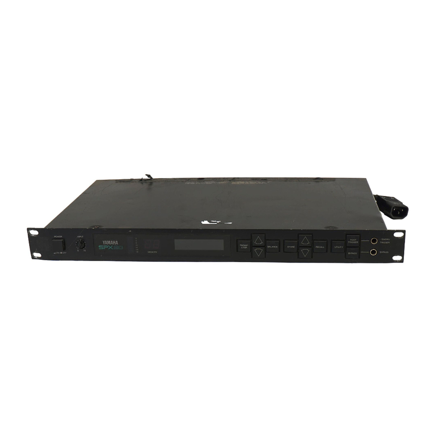
Page 4: Front Panel
These keys select any desired memory number to SPX90 for a few seconds after the power is turned call a specific program or store an edited program in the user memory area. The selected memory number is shown on the MEMORY NUMBER display. -
Page 5: Rear Panel
3 2 . User program This standard unbalanced mono 1/4” phone jack ac- 3 3 . User program 3. REV 2 VOCAL cepts the input signal to the SPX90. Input im- 34. User program pedance is 10 k-ohms. 4. REV 4 PLATE 5. -
Page 6: Basic Operations
BASIC OPERATIONS Before actually selecting or editing programs on your SPX90, make sure that all connections have been made pro- perly, and that the INPUT LEVEL switch, OUTPUT LEVEL switch, and INPUT LEVEL control have been properly set according to the source signal and equipment to which the SPX90 signal will be fed. -
Page 7: Store: Saving Edited Programs
NOTE: If you attempt to store a program in one of the read-only preset locations (1 through 30), the SPX90 will display the “# 1 ~ # 30 READ ONLY” error message. : SPX90 has an Edit Title Function, so you can which allows you to provide your own titles for edited programs. -
Page 8: Output Balance And Level Programming
1. Press the BALANCE key while any parameter is footswitch connected to the BYPASS jack. A normally- selected. closed-type footswitch such as the Yamaha FC-5 must be used. 2. The first function called will be BALANCE. Adjust the BALANCE of the effected and direct signal be- tween 0 and 100% using the PARAMETER INCRE- MENT/DECREMENT keys. -
Page 9: Utility Functions
MIDI control. For example, you can MIDI CONTROL Normal mode EDIT TITLE set the SPX90 so that when you select a specific voice MIDI PROGRAM CHANGE FOOTSWITCH on your MIDI synthesizer, the most appropriate effect MEMORY RECALL Normal mode. -
Page 10: Footswitch Memory Recall Range
SPX90 memory number (MEM) to be called when that program number is received. For example, if “PGM 12 = MEM 4” is set, SPX90 memory number 4 will automatically be called whenever voice number 12 is selected on your MIDI synthesizer. -
Page 11: Description Of Programs And Parameters
DESCRIPTION OF PROGRAMS AND PARAMETERS The preset programs in the SPX90 fall into the following types: REV (Reverb), ER1 and ER2 (Early Reflections), DELAY, ECHO, MOD (Modulation), GATE, PITCH, FREEZE, PAN, VIBRATO and PEQ (parametric equalizer). Each of these program types has a specific selection of programmable parameters. - Page 12 This effect, commonly used in contemporary record- Similar to Delay, Echo brings added dimension and force ings, produces independently variable left- and right- to both instrumental and vocal music. While Reverbera- channel signal delays. The result is an intriguing “doubl- tion recreates an abundance of partial sound reflec- ed”...
-
Page 13: Stereo Flange
CHORUS STEREO FLANGE A combination of Delay and LFO (Low Frequency With the Chorus effect, a violin, keyboard, or guitar can Oscillation) modulation, the popular Flanging effect can sound like an entire ensemble. Chorusing splits the in- dramatically thicken the sound of keyboard in- coming signal into three signals placed at the center, struments, or produce the “aircraft”... -
Page 14: Stereo Phasing
STEREO PHASING The SPX90 can produce a wide range of Phasing ef- This program is used to change the pitch of an input fects from a barely perceptible shift to a rapid pulsa- signal. Pitch can be changed in semitone increments tion. - Page 15 The FREEZE programs permit “recording” up to a 500-millisecond signal in the SPX90 memory; and play- to – 12 (one octave down). Pressing D4 on the ing it back as required. The FREEZE programs have two keyboard would produce a pitch increase of one tone basic steps: RECORD and PLAY.
-
Page 16: Freeze
Key. Then FC-5 works as the trigger switch when it is pressed. AUTO Mode If the AUTO mode has been selected, the SPX90 will automatically begin recording when an in- put signal of sufficient level is detected. The LCD displays “TRIGGER!” when the freeze function is triggered. - Page 17 5. PLAYBACK Another way to trigger playback is to use the Input Trig- To play back the recorded material, press the ger Parameter. Select the Input Trigger Parameter and PARAMETER key to enter the playback standby press the parameter Increment key to enter the stand- mode.
-
Page 18: Adr-Noise Gate
ADR-NOISE GATE This program feeds the reverb signal through a gate cir- cuit, making it possible to output only a segment of a This program uses a gate circuit to pass or shut off the longer reverb sound. Parameters provided for the reverb input signal in a number of ways. -
Page 19: Compressor
6. DECAY LEVEL. Range: 0 ~ 100% COMPRESSOR Determines the level at which the gate remains open for the HOLD TIME. The lower the value the lower The COMPRESSOR effect reduces the level of the attack the HOLD gate level. portion of a music signal and keeps overall signal level 7. -
Page 20: Auto Pan
TRIGGERED PAN AUTO PAN In this program the pan effect is triggered by the input This program automatically pans the sound image bet- ween left and right in the stereo sound field. Pan direc- signal or footswitch. tion, speed, and phase can be programmed. 1. -
Page 21: Delay Vibrato
This program makes it possible to add delay vibrato ef- This program permits variation of the input signal fre- fects to virtually any instrument or sound. When the quency response over an extremely broad range. input signal exceeds a programmed trigger level, the vibrato effect is cancelled and then gradually builds up to the programmed depth. -
Page 22: Sample Applications
Assuming the console used has independent effects or auxilliary send level controls on each input channel, it is possible to add the required amount of SPX90 effect to each input. It is also possible to use two SPX90 units for full stereo reverb and effects in a larger system. - Page 23 In a recording system it is most desirable to have the SPX90 input and outputs available at a patch bay where they may accessed and patched into virtually any part of the system. In some cases it might be best to have the SPX90 connected directly in line between the source and the mixing console inputs, while in other situations—final mixdown, for example—the SPX90 should be patched into the mixing console’s effects...
-
Page 24: Specifications
SPECIFICATIONS ELECTRICAL CHARACTERISTICS INPUT Dynamic Range Reverb: more than 75 dB Unbalanced x 1 (Phone Jack) Number of Channels Delay : more than 81 dB Nominal Level – 20 dBm/+4 dBm, Selectable Distortion Bypassed Signal: less than Impedance 10 k-ohms 0.01% Volume, Max. -
Page 26: Early Reflection Mode Chart
EARLY REFLECTION MODE CHART... -
Page 27: Room Size Chart
ROOM SIZE CHART... -
Page 28: Block Diagram
BLOCK DIAGRAM DIMENSIONS... -
Page 29: User Programming Table
USER PROGRAMMING TABLE Program No. Type Progaram Title New Value Parameter New Value Parameter Remarks Program No. Type Progaram Title New Value Parameter New Value Parameter Remarks... -
Page 30: Midi Implementation Chart
[ Digital Sound Processor ] Date : 10/5, 1985 Model SPX90 MIDI Implementation Chart Version : 1.0 Recognized Remarks Function . . . Basic Default 1 - 1 6 memorized Channel Changed 1 - 1 6 Default OMNI OFF/OMNI ON... - Page 31 SINCE 1887 NIPPON GAKKI CO., LTD. HAMAMATSU, JAPAN SERVICE The SPX90 is supported by Yamaha’s worldwide network of factory trained and qualified dealer service personnel. In the event of a problem, contact your nearest Yamaha dealer. 85124 printed in Japan OMD-163...