Table of Contents
Advertisement
AIR CONDITIONER
MULTI AIR CONDITIONER
AR07/09/12/15/18/24TSFABWKN
AR07/09/12/15/18/24TSFYBWKN
AJ009/012/018TNNDCH
AJ009/012/018TNLDCH
AJ009/012/015/018TNJDCH
1. Precautions
5. PCB Diagram
7. Reference Sheet
AJ020TXJ2CH
AJ024TXJ3CH
AJ036TXJ4CH
AJ048TXJ5CH
AJ020TXS3CH
AJ024TXS4CH
AJ030TXS4CH
AJ036TXS4CH
Advertisement
Table of Contents
Troubleshooting

Related Manuals for Samsung AR07TSFABWKN


Summary of Contents for Samsung AR07TSFABWKN
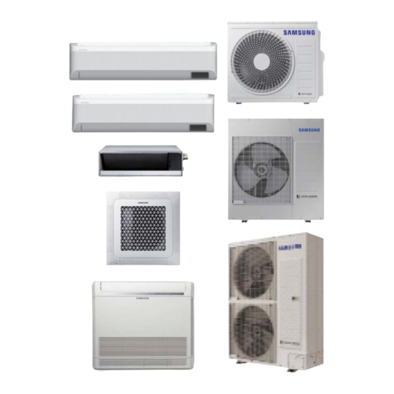
- Page 1 MULTI AIR CONDITIONER INDOOR UNIT OUTDOOR UNIT AR07/09/12/15/18/24TSFABWKN AJ020TXJ2CH AR07/09/12/15/18/24TSFYBWKN AJ024TXJ3CH AJ009/012/018TNNDCH AJ036TXJ4CH AJ009/012/018TNLDCH AJ048TXJ5CH AJ009/012/015/018TNJDCH AJ020TXS3CH AJ024TXS4CH AJ030TXS4CH AJ036TXS4CH AIR CONDITIONER CONTENTS 1. Precautions 2. Product Specifications 3. Disassembly and Reassembly 4. Troubleshooting 5. PCB Diagram 6. Wiring Diagram 7.
- Page 2 Contents 1. Precautions···································································································································1-1 1-1 Precautions for the Service ....................1-1 1-2 Precautions for the Static Electricity and PL...............1-1 1-3 During operation ........................1-2 1-4 Disposing of the unit ......................1-2 1-5 Precautions for the Pump Down ..................1-2 1-6 Others ............................. 1-2 2.
- Page 3 Contents 4-5 Setting to Cool or Heat only mode, checking and Cool/Heat modes operation test ......4-25 4-6 Fault Diagnosis by Symptom ....................4-27 4-6-1 Indoor.......................... 4-27 4-6-2 Outdoor unit is not powered on – Initial diagnosis ..........4-31 4-6-3 Checking Outdoor Controller ................. 4-32 4-6-4 Outdoor unit fan error....................
- Page 4 >3mm. • Do not extend an electric cord to the air conditioner. No Tapping and No Extension Cords • The air conditioner must be plugged in after you complete the installation. Samsung Electronics...
- Page 5 • Servicing shall be performed following the controlled procedure to minimize the risk of flammable refrigerant or gases. • For servicing with handling the R-32 refrigerant, use the special tools for the R32 refrigerant (manifold gauge, vacuu pump, charging hose, etc.). Samsung Electronics...
- Page 6 Universal Connection Multi Inverter(Free Joint Multi) Series delivers comfort to 2~5 rooms with a Single Outdoor Unit. Free Joint Multi added Universal indoor units, which can be universally connected to other Samsung outdoor units, to all lineup. · QMD Wind-Free ·...
- Page 7 When you want to operate all indoor units with the cooling mode or heating mode. SmartThings app is the easy way to turn your home into a smart home. Control the FJM with only one application. This feature is optional to the several models. Samsung Electronics...
- Page 8 6.35 6.35 Refrigerant Pipe 9.52 9.52 12.7 Type Cross Flow Fan Cross Flow Fan Cross Flow Fan Type BLDC BLDC BLDC Fan Motor Part Code DB61-00671A DB61-00671A DB61-00671A Heat Exchanger Row, Step 2R*10S 2R*10S 2R*10S Refrigerant Control Device Samsung Electronics...
- Page 9 Cross Flow Fan Cross Flow Fan Cross Flow Fan Cross Flow Fan Type BLDC BLDC BLDC BLDC Part Fan Motor Code DB31-00517A DB31-00517A DB31-00517A DB31-00517A Heat Exchanger Row, Step 2R*20S 2R*20S 2R*20S 2R*20S Refrigerant Control Device INCLUDED INCLUDED INCLUDED INCLUDED Samsung Electronics...
- Page 10 10.01 10.01 Part Type BLDC BLDC BLDC BLDC Fan Motor Code DB31-00579A DB31-00579A DB31-00579A DB31-00579A Row, Heat Exchanger 2R*36S 2R*36S 2R*46S 2R*56S Step Refrigerant Control Device Type R-410A R-410A R-410A R-410A Refrigerant Factory Charging 2200 2650 3100 3800 Samsung Electronics...
- Page 11 9.171 10.01 Part Type BLDC BLDC BLDC BLDC Fan Motor Code DB31-00579A DB31-00579A DB31-00579A DB31-00579A Row, Heat Exchanger 2R*46S 2R*46S 2R*46S 2R*56S Step Refrigerant Control Device Type R-410A R-410A R-410A R-410A Refrigerant Factory Charging 3400 3400 3400 3600 Samsung Electronics...
- Page 12 AJ009/012TNJDCH 15.7 AJ009/012TNJDCH 15.7 AJ009/012TNJDCH 15.7 AJ009/012TNJDCH 15.7 AJ009/012TNJDCH 15.7 AJ015TNJDCH 15.7 AJ015TNJDCH 15.7 AJ015TNJDCH 15.7 AJ015TNJDCH 15.7 AJ015TNJDCH 15.7 AJ015TNJDCH 15.7 AJ015TNJDCH 15.7 AJ015TNJDCH 15.7 AJ018TNJDCH 15.7 AJ018TNJDCH 15.7 AJ018TNJDCH 15.7 AJ018TNJDCH 15.7 AJ018TNJDCH 15.7 Samsung Electronics Samsung Electronics...
- Page 13 7 KBtu 9 Kbtu 12 Kbtu AR07/09/12/15/18/24TSFYBWKN 15 Kbtu 18 Kbtu 24 Kbtu 9 Kbtu 12 Kbtu AJ009/012/018TNNDCH 18 Kbtu 9 Kbtu AJ009/012/018TNLDCH 12 Kbtu 18 Kbtu 9 Kbtu 12 Kbtu AJ009/012/015/018TNJDCH 15 Kbtu 18 Kbtu Samsung Electronics Samsung Electronics 2-10...
- Page 14 Product Specifications 2-5 Accessory and Option Specifications 2-5-1 Indoor Unit Accessories Item Descriptions Code No. Q'ty Remark Ass'y drain hose Joint Cable-tie Insulation-Drain Hose Indoor Insulation-Drain Hose Unit Insulation-Drain Hose User Manual Installation Manual 2-11 Samsung Electronics...
- Page 15 Product Specifications Item Descriptions Code No. Q'ty Remark User Manual Installation Manual Insulation-Drain Hose Insulation-Drain Hose Indoor Insulation-Drain Hose Unit Rubber (Grommet Hanger) Insulation-Drain Ass'y Drain Hose Joint Cable-Tie Samsung Electronics 2-12...
- Page 16 Drain Plug DB67-00806A (AJ036TXJ4CH, AJ048TXJ5CH, AJ***TXS*CH) Rubber Leg DB73-20134A DB68-08737A (AJ020TXJ2CH, AJ024TXJ3CH) Installation Manual DB68-08940A (AJ036TXJ4CH, AJ048TXJ5CH, AJ***TXS*CH) (AJ020TXJ2CH) Nipple Connector DB67-00789A (AJ024TXJ3CH) (AJ020TXJ2CH) Flare Nuts DB60-30010B (AJ024TXJ3CH) (AJ***TX*4CH) DB96-16155A (AJ***TX*5CH) Ass'y Tube Connector (AJ020TXS3CH, DB96-16155B AJ***TX*4CH, AJ***TX*5CH) Samsung Electronics...
- Page 17 Disassembly and Reassembly 3. Disassembly and Reassembly Item Remark +Screw driver Monkey spanner Samsung Electronics...
- Page 18 2) Loosen each 9 screws(CCW) on Cabi-Top. (Use +Screw Driver). 3) Loosen 2 screws(CCW) fixed to assemble Plate Control Out with Cabinet-Side RH. (Use +Screw Driver.) 4) Loosen 10 fixing screws(CCW) on Cabinet- Side RH. (Use +Screw Driver.) Samsung Electronics...
- Page 19 (Use +Screw Driver.) Ass’y 1) Detach the Motor Wire from the PCB of Control Out Ass'y Control Out. 2) Detach comp wire and pressure switch- wire from the PCB of A’ssy Control Out. 3) Detach 2 Connect Wires from Reactor. Samsung Electronics...
- Page 20 4) Detach the Heat Exchanger. Befor you disassemble the pipes and Condensor, be sure that there should be no refrgerant remained in the unit. 5) Loosen 3 nuts of the Compressor. (Use Monkey Spanner.) 6) Detach the Compressor. Samsung Electronics...
- Page 21 1) Loosen 6 fixing screws (CCW) on the Cabinet-Side RH. (Use +Screw Driver). Cabi Front RH 1) Loosen 3 fixing screws (CCW) on the Cabinet-Front RH. (Use +Screw Driver). Cabi Top 1) Loosen 7 or 9 fixing screws (CCW) on the Cabi-Top. (Use +Screw Driver). Samsung Electronics...
- Page 22 Gurad Cond. (Use +Screw Driver). Cabi Back RH 1) Detach the Sensor from the Cabi-Back 2) Loosen 5 fixing screws (CCW) on Cabi- Back RH. (Use +Screw Driver). 3) Pull the hook of Cabi Back RH from the Bracket Valve. Samsung Electronics...
- Page 23 Parts Procedure Remark Plate Case Control 1) Loosen 2 fixing screws (CCW) on the Plate Support Case Control Support. (Use +Screw Driver). Cabi Front LF 1) Loosen 10 fixing screws (CCW) on the Cabinet-Front LF. (Use +Screw Driver). Samsung Electronics...
- Page 24 1) Detach the Motor Wire from PCB of A’ssy Control Out. 2) Loosen 4 fixing bolts (CCW) and detach the Motor. (Use +Screw Driver.) Backet Motor 1) Loosen 2 fixing screws (CCW) and detach the Bracket Motor. (Use +Screw Driver.) Samsung Electronics...
- Page 25 Disassembly and Reassembly Parts Procedure Remark Control Out 1) Detach Comp-Wire and Pressure-Wire from PCB of A’ssy Control Out. 2) Loosen 4 fixing screws (CCW) and detach the Bracket Motor. (Use +Screw Driver.) 3) Separate A’ssy Control Out. Samsung Electronics...
- Page 26 1) Disassemble the pipes in both inlet and outlet with welding torch. 2) Loosen 2 fixing screws (CCW) and detach the Bracket Valve. (Use +Screw Driver.) Compressor 1) Loosen fixing nut (CCW) on the Cover- Terminal. (Use Monkey Spanner or adjust- able Wrench.) 3-10 Samsung Electronics...
- Page 27 When assembling Comp Wire, make sure to match the color and location of the wire with the picture. Heat Exchanger 1) Loosen 2 fixing screws(CCW) on both sides. And loosen 1 fixed screws(CCW) Partition with base.(Use +Screw Driver.) Samsung Electronics 3-11...
- Page 28 2) Remove the 4 screws from the Cabinet Front RH and separate it. (Use + Screw Driver) Cabinet Top 1) Remove the 8 screws which is fixed to each side of cabinet top and separate it. (Use + Screw Driver) 3-12 Samsung Electronics...
- Page 29 Cabinet Back RH 1) Pull out the sensor from the cabinet back RH and separate it. 2) Remove the 4 screws which is fixed to each side cabinet back RH and separate it. (Use + Screw Driver) Samsung Electronics 3-13...
- Page 30 Plate Control 1) Remove the 1 screw from the Plate Conrtol and separate it. (Use + Screw Driver) Cabinet Front LH 1) Remove the 10 screws from the canbinet Front LF and separate it. (Use + Screw Driver) 3-14 Samsung Electronics...
- Page 31 Disassembly and Reassembly Parts Procedure Remark Cabinet Front LH 1) Remove the 2 fixing nuts like the picture on the right side. (Use Hexagon Wrench, Monkey Spanner, Hexagon Socket) Samsung Electronics 3-15...
- Page 32 Motor. ( Use + Screw Driver ) 3) Separate the Motor Wire connector from the Outdoor Unit Control Part. Bracket Motor 1) Remove the 2 screws from the Bracket Motor and separate it. (Use + Screw Driver) 3-16 Samsung Electronics...
- Page 33 Outdoor valve clogging error Miss matching error between indoor unit and outdoor unit : On : Flickering x: Off • If you turn off the air conditioner when the LED is flickering, the LED is also turned off. Samsung Electronics...
- Page 34 (Communication error for more than 2 minutes) : On : Flickering x: Off • If you turn off the air conditioner when the LED is flickering, the LED is also turned off. Samsung Electronics...
- Page 35 3minutes. Error of communication down between the indoor unit and wired remote controller after completion of 10 times tracking. Wired remote controller error COM1/COM2 Cross-installed error Error of master wired remote controller and slave wired remote controller setting Samsung Electronics...
- Page 36 ERROR ON PIPE IN-A TEMPERATURE SENSOR(SHORT OR OPEN) E331 ERROR ON PIPE IN-B TEMPERATURE SENSOR(SHORT OR OPEN) E332 ERROR ON PIPE IN-C TEMPERATURE SENSOR(SHORT OR OPEN) E333 ERROR ON PIPE IN-D TEMPERATURE SENSOR(SHORT OR OPEN) E334 ERROR ON PIPE IN-E TEMPERATURE SENSOR(SHORT OR OPEN) Samsung Electronics...
- Page 37 ERROR DUE TO INPUT CURRENT SENSOR OF INVERTER PBA(SHORT/OPEN) E488 INCOMING VOLTAGE SENSOR ERROR E500 IPM/PFCM OVERHEAT ERROR E554 THE REFRIGERANT LEAKS COMPLETELY FROM THE OUTDOOR UNIT ERROR DUE TO INDOOR UNIT SOFTWARE VERSION COMBINATION(INCOMPATIBLE INDOOR E563 UNITSOFTWARE ON A SYSTEM) E590 INVERTER EEPROM CHECKSUM ERROR Samsung Electronics...
- Page 38 The outdoor unit is communicating correctly with the indoor unit connected to refrigerant pipe E. At this point it is possible to start the internal units in the desired mode. NOTE manual before repeating the operating described in steps 1-2-3-4. Samsung Electronics...
- Page 39 Setting of Key and Display of the outdoor unit Push Pipe Checking Operation Cool Mode Try run Heat Mode Try run Reset Finish Key Operation - PCB MAIN - OUT - PCB MAIN – OUT (AJ020TXJ2CH, AJ024TXJ3CH) (AJ020TXS3CH, AJ***TX*4CH, AJ***TX*5CH) Samsung Electronics...
- Page 40 Condenser temperature EEV1 current step Outdoor temperature EEV2 current step Running current EEV3 current step EEV4 current step Total capacity of the indoor units Fan RPM (H: high, L: low, Blank: off ) Safety Control (just For Service Technician) Samsung Electronics...
- Page 41 Fast button Low Temp button Wind-Free button < AR**TSFYBWKN > Mode button Fast button High Temp button Low Temp button Eco button < AJ***TN*DCH > Mode button High Temp button High Fan button Low Temp button Low Fan button Samsung Electronics...
- Page 42 1 Press ❺ button to enter SEG6. 2 Press ❹ button to enter SEG8. Press ❶ button to be changed to FAN mode in the ON status. 1 Press ❺ button to enter SEG9 value. 2 Press ❹ button to enter SEG10 value. 4-10 Samsung Electronics...
- Page 43 1 Press ❺ button to enter SEG23 value. 2 Press ❹ button to enter SEG24 value. Press ❶ button to check whether the option code you entered is correct or not. Press operation button to enter option. Samsung Electronics 4-11...
- Page 44 • If you set the SEG 9 as 0, the indoor unit will maintain previous RMC ADDRESS even if you input the option value of SEG11~12. The MAIN address is for commnication between the indoor unit and the outdoor unit. Therefore, you must set it to operate the air conditioner properly 4-12 Samsung Electronics...
- Page 45 Indication Details Indication Details Indication Details Indication and details If you input a number other than 0~4 of the individual control of the indoor unit(SEG20), the indoor is set as “indoor 1”. • The window on/off function applies to the following unit Samsung Electronics 4-13...
- Page 46 • The external output of SEG15 is generated via MIM-B14 connection. (Refer to the manual of MIM-B14.) • If you set the Individual control with remote control (SEG20) option to a value other than 0 to 4, it is automatically set to 0 (Indoor 1). 4-14 Samsung Electronics...
- Page 47 Indication Details Indication Details Indication Details Indication Details Indication Details Indication Details Disuse Thermo Use of Disuse 1000 hours ON or OFF buzzer Indication control and Details OFF control Disuse Operation Window 2000 hours ON or OFF buzzer control Samsung Electronics 4-15...
- Page 48 Turn out in 180 min. without motion If you input a number other than 0~4 of the individual control of the indoor unit(SEG20), the indoor is set as “channel 1”. SEG23 is reserved in Mini 4Way 4-16 Samsung Electronics...
- Page 49 CAUTION If you set an indoor unit as the master indoor unit by using the remote control, the outdoor unit automatically operate in the current mode of the master indoor unit. Samsung Electronics 4-17...
- Page 50 020010 020010 SEG 31~36 100001 100001 100001 SEG 37~42 200000 200000 200000 SEG 43~48 300100 300100 300100 SEG 49~54 030000 030000 030000 SEG 55~60 100000 100000 100000 SEG 61~66 200000 200000 200000 SEG 67~72 300000 300000 300000 4-18 Samsung Electronics...
- Page 51 ● If you are going to use up to SEG 24, please refer to following instruction. SEG 18 : Not is use Change temperature display 0 (Celsius) 1 (Fahrenheit) Sound Mute ex) 044217-1d00e6-200000-300000 When using Sound mute : 044217-1d00e6-200002-300000 When using Fahrenheit and Sound mute : 044217-1d00e6-200003-300000 Samsung Electronics 4-19...
- Page 52 HEAT mode, and indoor fan and outdoor fan intermittently in a HEAT mode. heater operation. The compressor stops intermittently in a The compressor stops intermittently or the fan speed of the COOL mode or DRY mode, and fan speed of the indoor unit decreases. 4-20 Samsung Electronics...
- Page 53 Indoor Sub PCB (misconnecting or Sub PCB is out of order) Step 2 Address setting mode change to auto address setting. Step 3 Following auto address setting steps. Manual Address setting is Option in FJM PLUS A. Guidance Samsung Electronics 4-21...
- Page 54 Replace outdoor unit’s ass’y control or indoor Step 2 EEV Coil unit’s ass’y control. Basically, This error caused by communication between Indoor Units and Outdoor Unit. Guidance First of all, check the all communication connection and PCB’s status. 4-22 Samsung Electronics...
- Page 55 When system start in cooling mode, System don’t operate and display E441 Error code. Check point Remarks FJM PLUS is able to operate by -10 C Analysis But we admit that minimum Cooling temperature is by -5C Please, Remember cooling operation range. Samsung Electronics 4-23...
- Page 56 Please, Remember Heating operation range. - Try-run Check Error Contents While the system is working try-run mode, system turn off and display Check point Remarks Analysis try-run operation. * Refer to self-detection algorithm (Check Error Code meaning and check it out) 4-24 Samsung Electronics...
- Page 57 Example) • If you have selected desired option, you can shortly press the K2 switch to adjust the value of the Seg 3, Seg 4 and change the function for the selected option. Example) Samsung Electronics 4-25...
- Page 58 • If the outdoor unit is turned off and then immediately turned on again, the compressor does not operate for about 3 minutes. CAUTION • During the Cool mode, frost may temporarily develop on valves and other parts. • You can also test the Cool or Heat Try run using K1 button. NOTE 4-26 Samsung Electronics...
- Page 59 Current Resistance temperature (°C) 5.800 6.900 In this case, is the resistance 8.300 10.00 table on the right? 12.10 Indoor temperature sensor 14.70 failure (replace) 18.00 Restart the system after 22.00 replacing the PCB 28.30 33.90 42.30 Samsung Electronics 4-27...
- Page 60 Is the motor connector disconnected from the PCB? Connect the connector to PCB and restart the unit. Is there foreign substance stuck in the motor fan? and restart the unit. Replace the PCB and restart the unit. 4-28 Samsung Electronics...
- Page 61 PCB and replace the PCB Reconnect the cable connecting the outdoor unit to the indoor unit and restart the unit. If the communication still doesn’t work, replace the indoor unit PCB. Good +0.7V -0.7V Samsung Electronics 4-29...
- Page 62 EEPROM circuit failure. Symptom EEPROM component failure, EEPROM circuit parts missing/damaged/soldering Failure failure. Are the EEPROM circuit components in good conditions? soldering failure) Replace the PCB if the restart fails Restart the unit after replacing the PCB 4-30 Samsung Electronics...
- Page 63 Check the connection of the terminal block the terminal 2 (~) and 4 (~) of the bridge diode 220V? Is the fuse connected? Replace the fuse Is the reactor connector Connect the reactor. connected correctly? Replace the PBA. Samsung Electronics 4-31...
- Page 64 14.5V - 15.5V Main control 12V CE157 Voltage 10.8V - 13.2V Main control 5V CE159 Voltage 4.75V - 5.25V Check Resistance between R and S AJ020TXJ2CH, AJ024TXJ3CH AJ020TXS3CH, AJ***TX*4CH, AJ***TX*5CH (INVERTER PBA) Measuring point Resistance R - S 4-32 Samsung Electronics...
- Page 65 (CN901) during Replace the fan motor. the operation 1V~6V? Is the fan running the operation mode? Replace the fan motor. between pin6 and pin3 of the fan (CN901) fluctuate? (High 5V~6V, Low:0V~1V) Samsung Electronics 4-33...
- Page 66 AJ***TX*4CH AJ***TX*5CH Replace the compressor. between the compressor boday and the chassis in the range of Mega Is the compressor connection wire connected to the Check the connection wire. compressor correctly? Replace the outdoor unit Main PCB. 4-34 Samsung Electronics...
- Page 67 Trun off the power and reconnect the table. Trun off the power and correct or replace between pin6 and pin3 of the fan (CN901) fluctuate? the temperature sensor location. (High 5V~6V, Low:0V~1V) Samsung Electronics 4-35...
- Page 68 Is the sensor resistance Sensor Replace of 25°C? 30°C - 166kohm 35°C - 138kohm 40°C - 115kohm Connect the sensor to PBA connector sensor in the connector. Exchange the Outdoor PBA. Micom error or connector check. Exchange the Outdoor PBA. 4-36 Samsung Electronics...
- Page 69 Sensor Replace temperature of 25°C? 30°C - 8.31kohm 35°C - 6.94kohm 40°C - 5.83kohm Connect the sensor to PBA connector sensor in the connector. Exchange the Outdoor PBA. Micom error or connector check. Exchange the Outdoor PBA. Samsung Electronics 4-37...
- Page 70 The parts should be replaced in the following procedure. The repair is completed. Check the operation of the new part. Replace it with a new part. Detach the faulty part. Check for any faulty part. Set an address. 4-38 Samsung Electronics...
- Page 71 PCB Diagram 5. PCB Diagram 5-1 Indoor unit Mini 4Way This Document can not be used without Samsung’s authorization. Samsung Electronics...
- Page 72 #5 : EEPROM_SO #6 : EEPROM_SI #7 : EEPROM_CLK 22. CN401- HUMAN 24. TE04- 20. CN804-VENTILATOR 21. CN311-2 WIRED SUB 23. CN801-SPI SENSING COMMUNICATION #1 : COM1(F1) #2 : MAIN-HUMAN #2 : COM1(F2) SENSOR COMM(TXD) SENSOR COMM(RXD) #6 : COM2(F4) Samsung Electronics...
- Page 73 PCB Diagram Mini 4Way (PANEL) - This Document can not be used without Samsung’s authorization. 1. CN01-DISPLAY #2 : LED_Operation #4 : LED_Timer #5 : - #6 : LED_Filter #7 : - #8 : Remocon Signal Out #9 : Panel Select...
- Page 74 PCB Diagram Home Duct Samsung Electronics...
- Page 75 7. CN81-COMP ERROR 8. CN412-ROOM 9. CN411-FLOAT SW 10. CN83-EXT T 101. CN301-DOWNLOAD 12. CN501-DISPLAY For Developer only,Not available in Actual Site 13. CN905-FAN MOTOR 14. CN201-EEPROM 15. CN808-EEV(DVM) 16. CN804-VENT #5EEPROM_SO 17. CN801-SPI 18. CN311-2WIRE 19. CN302-COM1 COM2 Samsung Electronics...
- Page 76 PCB Diagram Console Samsung Electronics...
- Page 77 14. CN201-EEPROM 15. CN808-EEV(DVM) 16. CN801-SPI #2 : NOT USED #4 : NOT USED 17. CN311-2WIRE SUB 18. CN804-VENTILATOR 19. CN302-COMMUNICATION 20. CN703-BLDC MOTOR #1~2 : COM1 COMMUNICATION #2~5 : COMMUNICATION #7~12 : COMMUNICATION #4~6 : COM2 COMMUNICATION Samsung Electronics...
- Page 78 7. CN571- EARTH TAP TERMINAL 8. CN002-L/TAP TERMINAL #1 : L/RELAY CONTACT #1 : N #1 : EARTH #1 :L #2 : - 9. CN581-ECO COMM 10. CN401, 402, 403-COMP 11. CN051, 052-REACTOR 12. CN551-DOWNLOAD #1~7 : ECO COMM port Samsung Electronics...
- Page 79 PCB Diagram AJ020TXJ2CH, AJ024TXJ3CH (MAIN PBA) Samsung Electronics...
- Page 80 #5 : R1 #6 : R2 18. CN301 - ODU 19. CN305 - COMMUNICATION 16. CN801 - EEV D 17. CN201 - EEPROM COMMUNICATION EMI EARTH #1 : F1 #1 : EARTH #2 : - #2 : F2 Samsung Electronics...
- Page 81 8. CN911 - FAN MOTOR 2 COMMUNICATION COMPRESSOR #1 : RXD #2 : TXD #2 : N.C #2 : N.C #5 : FAN RPM #5 : FAN RPM #6 : FAN RPM FEEDBACK #6 : FAN RPM FEEDBACK Samsung Electronics 5-11...
- Page 82 PCB Diagram AJ020TXS3CH, AJ***TX*4CH, AJ***TX*5CH (MAIN PBA) 14 15 16 5-12 Samsung Electronics...
- Page 83 #1 : L - RELAY CONTACT SENSOR #2 : - OUTPUT #2 : - TEMPERATURE SENSOR INPUT OUTPUT TEMPERATURE SENSOR #7 : OLP TEMPERATURE SENSOR 16. CN845 - BASE HEATER #1 : L - RELAY CONTACT OUTPUT #2 : - OUTPUT Samsung Electronics...
- Page 84 PCB Diagram AJ020TXS3CH, AJ***TX*4CH, AJ***TX*5CH (MAIN PBA) - This Document can not be used without Samsung’s authorization. 1. L1 - AC POWER OUTPUT 2. L2 - AC POWER OUTPUT 3. CN01 - AC POWER OUTPUT 4. EARTH #1 : L - RELAY CONTACT...
- Page 85 Wiring Diagram 6. Wiring Diagram 6-1 Indoor Unit This Document can not be used without Samsung’s authorization. Samsung Electronics...
- Page 86 Wiring Diagram This Document can not be used without Samsung’s authorization. Samsung Electronics...
- Page 87 Wiring Diagram This Document can not be used without Samsung’s authorization. Samsung Electronics...
- Page 88 Wiring Diagram 6-2 Outdoor unit This Document can not be used without Samsung’s authorization. Samsung Electronics...
- Page 89 Wiring Diagram This Document can not be used without Samsung’s authorization. Samsung Electronics...
- Page 90 Contact CAUTION your dealer for advice. • Minimum installation height of indoor unit is 0.6 m for floor mounted, 1.8 m for wall, 2.2 m for ceiling. Samsung Electronics...
- Page 91 7-1-2 Outdoor Unit table below. Model Name Total connecting pipe length (L) Chargeless Chargeless Chargeless Chargeless 8. Make sure that you install the outdoor unit in an area which is large enough to accommodate the measurements lighting. Samsung Electronics...
- Page 92 (N · m) port cap (Refer to the table) ø 6.35 20 to 25 ø 9.52 20 to 25 10 to 12 ø 12.70 25 to 30 R-140A : Diameter of the screw-1/2-20UNF ø 15.88 30 to 35 Samsung Electronics...
- Page 93 4) Set the unit to cool operation mode. 5) Check the pressure indicated by the pressure gauge(low pressure side). a regular and high operation mode. AJ034NCJ5CH, AJ020TXS3CH AJ***TX*4CH AJ038NCJ5CH AJ***TX*5CH erant until the rated pressure is reached. pressure valve. Samsung Electronics...
- Page 94 Tightening torque Outer diameter (mm) Body cap (N · m) Charging port cap (N · m) ø 6.35 20 to 25 ø 9.52 20 to 25 10 to 12 ø 12.70 25 to 30 ø 15.88 30 to 35 Samsung Electronics...
- Page 95 6. Make sure you do not bend the connection pipes in the middle and store together with the cables. 7. Move the indoor and outdoor units to a new location. 8. Remove the mountin g plate for the indoor unit and move it to a new location. Samsung Electronics...
- Page 96 Wi-Fi + Tri-care Filter X 1,000 Btu/h (2digits) Indoor Wi-Fi Tri-care Filter (3) Year (10) Buyer 2013 America (6) Design 2014 Europe Wind-Free, GEO 2015 Wind-Free, AIRISE 2016 2017 AIRISE 2018 2019 2020 (4) Inverter type HP, R410A HP, R32 Samsung Electronics...
- Page 97 Europe 2016 2017 2018 (7) Rating voltage 2019 2020 220V, 60Hz 208~230, 60Hz 220~240V, 50/60Hz 200~220V, 50Hz (4) Inverter type 220~240V, 50Hz 127V, 50Hz Indoor unit (NASA) Outdoor unit (NASA) Indoor unit (Non NASA) Outdoor unit (Non NASA) Samsung Electronics...
- Page 98 (7) Rating voltage 2015 2016 220V, 60Hz 2017 208~230, 60Hz 220~240V, 50/60Hz 2018 200~220V, 50Hz 2019 220~240V, 50Hz 127V, 50Hz 2020 (4) Product type Indoor unit (NASA) Outdoor unit (NASA) Indoor unit (Non NASA) Outdoor unit (Non NASA) Samsung Electronics...
- Page 99 Samsung Electronics...
- Page 100 Samsung Electronics 7-11...
- Page 101 7-12 Samsung Electronics...
- Page 102 Samsung Electronics...
- Page 103 One that compresses, especially a machine used to compress gases. (Full name compressor) BLOWER air. ASS’Y CONTROL BOX MOTOR Something, such as a machine or an engine, that produces or imparts motion. (Full name : assemble evaporator / assemble condenser) 7-14 Samsung Electronics...
- Page 104 There are no components in the air conditioner irritating the eyes and sending out chemical smells. But, when the air conditioner is turned on, other smell sources are sucked into the air conditioner Smells place, a pharmacy, a gasoline handling place, a tire shop, a second-hand book shop or an electronic Samsung Electronics 7-15...
- Page 105 It occurs generally when there are pet animals in the house. Their smells stay at the same place. It sends out bad smells. It won't start. Operation erly. The remote controller won't operate. EMI. In this case, take the remote controller closer to the receiver. 7-16 Samsung Electronics...
- Page 106 There is a cost table. But, our service engineer needs to visit to total up the cost correctly. When you move in, make sure to contact Samsung Electronics Service Center or Authorized Service Agent in advance to streamline the process.
- Page 107 7-18 Samsung Electronics...
- Page 108 China china.samsungportal.com © Samsung Electronics Co., Ltd. January. 2020. This Service Manual is a property of Samsung Electronics Co., Ltd. Printed in Korea. Any unauthorized use of Manual can be punished under Code No. AC-00261E_1 applicable International and/or domestic law.