Table of Contents
Advertisement
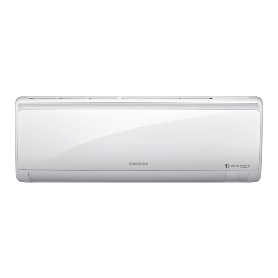
AIR CONDITIONER
AR09RXFPEWQNEU
AR12RXFPEWQNEU
AR18RXFPEWQNEU
AR24RXFPEWQNEU
AR09RXFPEWQXEU
AR12RXFPEWQXEU
AR18RXFPEWQXEU
AR24RXFPEWQXEU
SPLIT-TYPE AIRCONDITIONER
INDOOR UNIT
MODEL CODE
AR09RXFPEWQNEU
AR12RXFPEWQNEU
AR18RXFPEWQNEU
AR24RXFPEWQNEU
CONTENTS
1. Precautions
2. Pr
cations
3. Alignment and Adjustments
4. Disassembly and Reassembly
5. ASSY CONTROL
6. Electrical Parts List
7. Wiring Diagram
8. PCB Diagram
9. Operating Instructions
10. Troubleshooting
11.Block Diagram
12. Reference Sheet
OUTDOOR UNIT
AR09RXFPEWQXEU
AR12RXFPEWQXEU
AR18RXFPEWQXEU
AR24RXFPEWQXEU
Advertisement
Table of Contents

Related Manuals for Samsung AR09RXFPEWQNEU


Summary of Contents for Samsung AR09RXFPEWQNEU
- Page 1 SPLIT-TYPE AIRCONDITIONER INDOOR UNIT OUTDOOR UNIT MODEL CODE AR09RXFPEWQNEU AR09RXFPEWQXEU AR12RXFPEWQNEU AR12RXFPEWQXEU AR18RXFPEWQNEU AR18RXFPEWQXEU AR24RXFPEWQNEU AR24RXFPEWQXEU AIR CONDITIONER CONTENTS 1. Precautions 2. Pr cations 3. Alignment and Adjustments AR09RXFPEWQNEU 4. Disassembly and Reassembly AR12RXFPEWQNEU AR18RXFPEWQNEU 5. ASSY CONTROL AR24RXFPEWQNEU 6. Electrical Parts List 7.
-
Page 2: Table Of Contents
Contents 1. Precautions 1-1 Installing the air conditioner 1-2 Power supply and circuit breaker 1-3 During operation 1-4 Disposing of the unit 1-4 Others 2. Product Specications 2-1 The Feature of Product 2-2 Product Specifications 2-3 The comparative specifications of product 2-4 Accessory and option specifications 3. - Page 3 Contents 9. Operating Instructions 9-1 Name of Each Part 9-2 Wireless Remote Control-Buttons and Display 10. Troubleshootin 10-1 Items to be checked First 10-2 Communication Error 10-2-1 Communication Error 10-2-2 Indoor temperature sensor Error 10-2-3 Indoor fan motor speed detecting error (BLDC fan) 10-2-4 Outdoor temperature sensor error 10-2-5 Outdoor Cond temperature sensor error 10-2-6 Outdoor Discharge temperature sensor error...
-
Page 4: Precautions
1. Precautions 1-1 Installing the air conditioner • Uses should not install the air conditioner by themselves. Ask the dealer or authorized company to install the air conditioner except window-type air conditioner in U.S.A and Canada. • If you don't install the air conditioner properly, it may cause a fire, a water leakage or an electric shock. • You must install the air conditioner according to the national wiring regulations and safety regulations. -
Page 5: Disposing Of The Unit
1-4 Disposing of the unit • Before the throwing out the air conditioner, remove the batteries from the remote control. • When you dispose of the air conditioner, consult your dealer. If pipes are removed incorrectly, refrigerant may blow out and cause air pollution. When it contacts with your skin, it can cause skin injury. • The package of the air conditioner should be recycled or disposed of properly for environmental reasons. -
Page 6: Product Specications
2. Product Specications 2-1 The Feature of Product 2-step cooling 2-step cooling function will quickly cool the room to reach the desired temperature and then it will adjust the fan speed and ai ow direction automatically to help you stay comfortable and refreshed. -
Page 7: Product Specifications
2-2 Product specification Model AR09RXFPEWQ/EU AR12RXFPEWQ/EU AR18RXFPEWQ/EU AR24RXFPEWQ/EU Rating Mode Unit Wall-mounted Wall-mounted Wall-mounted Wall-mounted T1 Cool 2750 3500 5000 6500 Capacity T3 Cool Heat 3200 3500 6000 7400 T1 Cool 1220 1390 1950 Power T3 Cool Input Heat 1745 2350 T1 Cool Current... -
Page 8: The Comparative Specifications Of Product
2-3 The comparative specification of product DEVELOPMENT MODEL Model AR09RXPXBWK/EU AR12RXPXBWK/EU Indoor Unit Design Outdoor Unit Indoor Unit Net Weight Outdoor Unit 22.8 22.8 Indoor Unit 820*280*215 820*280*215 Net Dimension Outdoor Unit 660*475*242 660*475*242 Indoor Unit Noise Outdoor Unit Air Purifying System EASY CLEAN FILTER EASY CLEAN FILTER Indoor Display... -
Page 9: Accessory And Option Specifications
2-4 Accessoray and option specifications Item Descriptions Code No. Q’ty Remark DB90-04558A (M1) ASSY-PLATE HANGER DB90-06524A (M3) ASSY WIRELESS REMOCON DB93-15882Q Indoor unit case BATTERY 4301-000121 MANUAL USERS DB68-08176A MANUAL INSTALL DB68-08177A Rubber Leg DB67-01533A Outdoor unit case DB67-20011A Drain plug... -
Page 10: Alignment And Adjustments
3. Alignment and Adjustments 3-1 Test Mode How to Approach Test Mode You can approach the test mode by pressing the on/off switch of indoor unit for 5 seconds. Test mode operation option After installing the air conditioner, check whether each subordinate is normally operated or not by operating the test mode. -
Page 11: Display Error And Check Method
3-2 Display Error and Check Method 3-2-1 Indoor Display Error and Check Mathod ERROR MODE LED1 LED2 LED3 DESCRIPTION 7-SEG Operation Timer Option Communication error E101 , E102 (Indoor <-> Outdoor) ROOM TH sensor error E121 INDOOR MID, INDOOR IN PIPE-TH E122, E123 sensor error Fan error (Indoor) - Page 12 3-2 Display Error and Check Method 3-2-2 Outdoor Display Error and Check Mathod ERROR MODE DESCRIPTION 7-SEG Power off /VDD NG Power on reset (1sec) Normal operation Abnormal communication (Indoor <-> Outdoor) IPM over current (O.C) error E464 Comp. strating error E461 EEPROM data error (no data) E470...
-
Page 13: Setting Option Setup Method
3-3 Setting Option Setup Method Ex) Option No. : Step 1 Enter the Option Setup mode. 1. Tack out the batteries of remote control. 2. Press the temperature button simultaneously and insert the battery again. 3. Make sure the remote control display shown as Step 2 Enter the Options Setup mode and select your options asscording to the following procedure. - Page 14 Method Display Press the button to set Dry mode. Setting option SEG5 Press the button the display panel to . … Press the button repeatedly to select . Setting option SEG6 Press the button the display panel to . … Press the button repeatedly to select .
- Page 15 Method Display Press the button to set Auto mode. Setting option SEG11 Press the button the display panel to . … Press the button repeatedly to select . Setting option SEG12 Press the button the display panel to . … Press the button repeatedly to select .
- Page 16 설정방 법 표시 부 Press the button to set Fan mode. Setting option SEG17 Press the button the display panel to . … Press the button repeatedly to select . Setting option SEG18 Press the button the display panel to . …...
- Page 17 설정방 법 표시 부 Press the button to set Fan mode. Setting option SEG17 Press the button the display panel to . … Press the button repeatedly to select . Setting option SEG18 Press the button the display panel to . …...
-
Page 18: Disassembly And Reassembly
4. Disassembly and Reassembly Necessary Tools Item Remark +SCREW DRIVER Q’ty 1 ea. To assembly and disassembly the screw MONKEY SPANNER Q’ty 1 ea. To assembly and disassembly the Fan motor and Compressor - SCREW DRIVER Q’ty 1 ea. To assembly and disassembly the screw... -
Page 19: Indoor Unit
4-1. Indoor Unit Parts Procedure Remark PANEL-FRONT 1) Stop the driving of air conditioner and shut off main power supply. 2) Open the FRONT-GRILLE and pull out from the PANEL-FRONT. 3) Detach COVER-TERMINAL from the PANELFRONT.(use + Screw Driver) 4) Loosen connector wire(white) and detach the temperature sensor wire. - Page 20 Parts Procedure Remark TRAY DRAIN 1) Loosen stepping motor wire and detach the hook of main frame. 2) To detach TRAY-DRAIN from the main frame, pull the bottom of the TRAY-DRAIN towards you. CONTROL IN 1) Unfasten the earth screw.(use + Screw Driver) 2) Detach COVER-CONTROL from the CASECONTROL.
- Page 21 Parts Procedure Remark 5) Take o the CASE-CONTROL CONTROL IN from the main frame. 1) Unfasten the screw. 2) Cut the cable tie. 3) Loosen the terminal block wires. i Caution: The terminal is locking type. So, when you separate termi- nals, pull pressing the button.
- Page 22 Parts Procedure Remark 4) Loosen the Motor connector Caution: When you separate the connector, pull pressing the locking button. 5) Loosen Stepping MOTOR con- nector. Caution: When you separate the connector, pull pressing the locking button. 6) Loosen Main Power connector. Caution: When you separate the connector, pull pressing the locking button.
- Page 23 Parts Procedure Remark EVAPORATOR 1) Unfasten the screw at the right side. (use + Screw Driver) 2) Unfasten the screw at the left side. (use + Screw Driver) 3) Detach the HOLDER PIPE. 4) Take o the EVAPORATOR from the main frame.
- Page 24 Parts Procedure Remark FAN MOTOR 1) Unfasten the screw in the & HOLDER-EVAP on the left side of CROSS FAN evaporator.(use + Screw Driver) 2) unfasten the 3 points screws in the CASECONTROL, and then detach the CASE. (use + Screw Driver) 3) unfasten the screw a little.(use + Screw Driver) 4) Lift up the evaporator slightly...
-
Page 25: Outdoor Unit
4-2. Outdoor Unit (N-V2MD) AR09RXFPEWQXEU AR12RXFPEWQXEU Parts Procedure Remark Common Work 1) First, stop the operation of the air conditioner, please cut off the supply of power. 2) Please separate outdoor after loosen the bottom screw 3EA of the front three places. (+ screw driver Use) 3) Please separate the positions of the sides screw 1EA (+ screw driver... - Page 26 Parts Procedure Remark 6) Please remove the screw 4ea located on the rear panel. (use + screwdriver) 7) Please separate the screw 2ea located on the side panel. (+ screw driver Use) 8) Please separate the screw 4ea located on the side panel. (+ screw driver Use) 9) Please remove the COVER CONTROL OUT downward.
- Page 27 Parts Procedure Remark 10) Please allign the wire such as picture if you re-assemble after separate connector w ir e . If the connector is excessively folded, there is a risk of fire. 11) Please remove the CABINET SIDE upward direction. FAN & MOTOR 1) Please Loosen the NUT 1ea clockwise.
- Page 28 Parts Procedure Remark 3) Remove the fixing points of the mo- tor SCREW 2ea, please disconnect the MOTOR turning coun- terclockwise. Capillary 1) Please remove the weld point in one place. (COND-OUT) If you remove the compressor and heat exchanger, eliminate the refriger- ant inside the compressor and heat exchanger completely with welding fire to remove the PIPE.
- Page 29 Parts Procedure Remark 2) Please separate the two sides fixing screws loose. (+ SCREW DRIVER Use) Compressor 1) Please disassemble one NUT counterclockwise (using MONKEY SPANNER) [OLP external compressor] 2) Disassemble COVER- TERMINAL after remove the OLP. BE CAUTION Engraved position : C (black), S (white), R (red) [OLP internal compressor] 2) Please disassemble COVER-...
- Page 30 Parts Procedure Remark ※ how to distinguish from OLP internal, external compressor : Check the compressor label 3) Please remove the compressor after loosen the compressor fixed NUT 3ea. (Using MONKEY SPANNER) 4) Please detach the two welds. (SUCTION, DISCHARGE)
- Page 31 4-3. Outdoor Unit (Q-480) AR18RXFPEWQXEU AR24RXFPEWQXEU Parts Procedure Remark COMMON 1) Loosen fixing screws from the WORK cabi side Rh and detach it. 2) L oosen each sc rews and detach the Cabi Top Cover. 3) Loosen fixing screws from the cabi side. 4) Loosen fixing screws from the cabi side Rh and detach it.
- Page 32 Parts Procedure Remark COMMON 5) Loosen fixing screws from the WORK cabi front and detach it. 6) L oosen fixing screws from the Cabi left and detach it and Remove the 4 Cond Bar from the holderof outdoor unit cabinet.
- Page 33 Parts Procedure Remark 1) Detach the Nut Flange like the & picture on the right side. Motor (Turn clockwise because the screw is left-handed.) (Use Monkey Spanner.) 2) Detach the Fan Propeller. 3) Loosen 4 fixing screws to detach the Motor. (Use Monkey Spanner.) 4) Disconnect the wire between Assy Control Out and Motor.
- Page 34 Parts Procedure Remark Assy 1) To remove the Cover control box : Control Out Pull the motor wire is allow sufficient space as shown on the right side and then remove the screw. 2) Detach several connectors from the Assy Control Out. 3) Detach several connectors from the PCB of Assy Control Out.
- Page 35 Parts Procedure Remark Compressor 1) Loosen the ng nut and detach the Compressor Lead Wire. (Use Monkey Spanner.) 2) Loosen the bolts at the bottom of Compressor like the picture on the right side. (Use Monkey Spanner.)
-
Page 36: Assy Control
5. ASSY CONTROL 5-1 ASSY KIT CODE DB92-04454D AR09RXFPEWQNEU AR12RXFPEWQNEU Name Code Q'ty Unit ASSY CASE ELECTRIC DB90-09432C PBA NEW STD#5 DB92-03467G ASSY CONNECTOR WIRE DISPLAY DB93-11217C ASSY THERMISTER DB95-05163A ASSY CONNECTOR EARTH DB93-06676A... -
Page 37: Assy Kit Code Db92-04454H
5-2 ASSY KIT CODE DB92-04454H AR18RXFPEWQNEU AR24RXFPEWQNEU Name Code Q'ty Unit ASSY CASE ELECTRIC DB90-09431A PBA NEW STD#5 DB92-03467G ASSY CONNECTOR WIRE DISPLAY DB93-11217C ASSY THERMISTER DB95-05163A ASSY CONNECTOR WIRE DB93-06676A ASSY CONNECTOR WIRE DB93-10943H... -
Page 38: Assy Kit Code Db92-04376B
5-3 ASSY KIT CODE DB92-04376B AR09RXFPEWQXEU AR12RXFPEWQXEU Name Code Q'ty Unit SCREW-TAPPING 6002-000536 SCREW-TAPPING 6002-000231 SCREW-TAPPING 6002-000239 SCREW-TAPPING 6002-000555 SCREW-SPECIAL 6009-001001 HOLDER-WIRE CLAMP DB61-02200A RUBBER DB67-01534A CASE CONTROL-UPPER S DB61-06600A COVER-CONTROL-UPPER DB63-03378A INSIDE PLATE-CONTROL OUT DB61-06715B PLATE-CONTROL LOW DB61-06713A CASE CONTROL-OUT DB61-06714A HEAT SINK DB62-12196B... -
Page 39: Assy Kit Code Db92-04378B
5-4 ASSY KIT CODE DB92-04378B AR18RXFPEWQXEU Name Code Q'ty Unit GREASE-SILICON 0205-000178 0.002 ASSY CONNECTOR WIRE DB93-07452B SCREW-TAPPING 6002-000536 HEAT SINK DB62-12196B COVER PCB DB63-03885A ASSY CONNECTOR WIRE- DB93-16402A COMM PLATE CONTROL DB61-04690A CASE CONTROL DB61-06722A ASSY-SCREW MACHINE DB91-00933A ASSY PCB MAIN DB92-04029D ASSY PCB MAIN DB92-04025C... -
Page 40: Assy Kit Code Db92-04379B
5-5 ASSY KIT CODE DB92-04379B AR24RXFPEWQXEU Name Code Q'ty Unit SCREW-TAPPING 6002-000239 CASE CONTROL-UPPER DB61-04677A CABLE TIE DB65-10088D SCREW-TAPPINGM4,L16 6002-000234 SCREW-TAPPING M4,L25 6002-000555 SCREW-SPECIAL,M4,L10 6009-001001 HOLDER-WIRE CLAMP DB61-00250A PLATE-CONTROL OU DB61-04698A TERMINAL BLOCK DB65-00274A TERMINAL BLOCK DB65-00298B ASSY CONNECTOR WIRE DB93-09495N ASSY CONNECTOR WIRE- DB93-12121B... -
Page 41: Electrical Parts List
6. Electrical Parts List 6-1 INDOOR MAIN PCB CODE DB92-03467G Parts Code Design Loc Parts Description Spec. Quantity Unit 0201-001528 ADHESIVE-SIL ADHESIVE-SIL LDC2577D,Y/GRN,175CPS 0202-001463 SOLDER-WIRE SOLDER-WIRE LFC2-W3.0,D3,99.79Sn/0.2Cu/0.01P,No Flux SOLDER-WIRE 0202-001608 SOLDER-WIRE FLUX LFC7-107,D0.8,99.3Sn/0.7Cu/0.01P,Flux 3.5% FLUX 0204-004665 FLUX FLUX KSP-70M-S,MIXTURE,NO,FLUX,13% 0204-005794 SOLVENT SOLVENT S-1000,(CH3)2CHOH,100%,0.79... - Page 42 Parts Code Design Loc Parts Description Spec. Quantity Unit HEADER-BOARD TO 3711-006678 CNS32 BOX,10P,1R,2mm,STRAIGHT,SN,BLU CABLE 3712-001047 CNP73 CONNECTOR-TERMINAL TAB,MALE,N,0.5/4.75mm CV1615280,COIL CHOKE,28.0mH,+50~- DB27-00096A FT71 COIL CHOKE 30%,268.0m ohm,1.5A,66,21*22*15.5*4,13x10, Mn-Zn,4,DIP DB67-00942A VA71-1 VIVALDI-P/J,SHP2,1,5.2,11.5,18.5,GREEN,SSEC MAIN,NEW BORACAY,120*120,Y,220- DB94-06021A ASSY PCB AUTO 240V,19V,12V,5V,15W,485-INV,BLDC FAN,NO Y-CAP,DB92-03467J 0501-000362 Q801 TR-SMALL SIGNAL KSC2328A-Y,NPN,1000mW,TO-92L,TP,160~320 KIA431A,TO-92,3P,4.7x4.8mm,PLASTIC,700mW,- 1203-003318...
- Page 43 Parts Code Design Loc Parts Description Spec. Quantity Unit 393,SOP,8P,150MIL,DUAL,36V,CMOS,PLASTIC,18 1202-000104 IC12 IC-VOLTAGE COMP. V,780mW,0to+70C,18V,5mV,250nA,50NA,30 KA78R15,TO-220,4P,10x15mm,PLASTIC,14.6/15.4 1203-002722 REG701 IC-POSI.FIXED REG. V,1.5W,-20to+80C,ST KIA7033AT,TSM,3P,2.9x1.6x0.7mm,PLASTIC,3.3V, 1203-006245 IC03 IC-VOL. DETECTOR 350mW,-30to+85C,TP 2007-000033 R826 R-CHIP 0ohm,5%,1/4W,TP,3216 2007-000040 R113 R-CHIP 150ohm,1%,1/10W,TP,1608 2007-000070 R717 R-CHIP 0ohm,5%,1/10W,TP,1608,T0.45 2007-000076 R601 R-CHIP 330ohm,5%,1/10W,TP,1608...
- Page 44 Parts Code Design Loc Parts Description Spec. Quantity Unit 2007-000148 R111 R-CHIP 10Kohm,5%,1/16W,TP,1005,T0.35 2007-000148 R501 R-CHIP 10Kohm,5%,1/16W,TP,1005,T0.35 2007-000148 R502 R-CHIP 10Kohm,5%,1/16W,TP,1005,T0.35 2007-000148 R507 R-CHIP 10Kohm,5%,1/16W,TP,1005,T0.35 2007-000148 R514 R-CHIP 10Kohm,5%,1/16W,TP,1005,T0.35 2007-000148 R521 R-CHIP 10Kohm,5%,1/16W,TP,1005,T0.35 2007-000148 R522 R-CHIP 10Kohm,5%,1/16W,TP,1005,T0.35 2007-000148 R523 R-CHIP 10Kohm,5%,1/16W,TP,1005,T0.35 2007-000148 R524...
- Page 45 Parts Code Design Loc Parts Description Spec. Quantity Unit 2007-007313 R402 R-CHIP 6.8Kohm,1%,1/16W,TP,1005,T0.35 2007-007313 R403 R-CHIP 6.8Kohm,1%,1/16W,TP,1005,T0.35 2007-007455 R110 R-CHIP 24.9Kohm,1%,1/10W,TP,1608 2007-009922 R301 R-CHIP 300Kohm,1%,1/4W,TP,3216,T0.55 2007-009922 R302 R-CHIP 300Kohm,1%,1/4W,TP,3216,T0.55 2007-009922 R303 R-CHIP 300Kohm,1%,1/4W,TP,3216,T0.55 2007-010635 R106 R-CHIP 6.8ohm,1%,1/10W,TP,1608,T0.3 2203-000257 C705 C-CER,CHIP 10nF,10%,50V,X7R,TP,1608 2203-000257 C801...
- Page 46 Parts Code Design Loc Parts Description Spec. Quantity Unit 2203-007456 C523 C-CER,CHIP 1000nF,10%,25V,X5R,TP,1005,T0.5 2203-007456 C526 C-CER,CHIP 1000nF,10%,25V,X5R,TP,1005,T0.5 2203-007456 C528 C-CER,CHIP 1000nF,10%,25V,X5R,TP,1005,T0.5 2203-007456 C551 C-CER,CHIP 1000nF,10%,25V,X5R,TP,1005,T0.5 2203-007456 C552 C-CER,CHIP 1000nF,10%,25V,X5R,TP,1005,T0.5 2203-007486 C804 C-CER,CHIP 1000nF,10%,50V,X5R,TP,1608 2402-001145 C701 C-AL,SMD 47uF,20%,50V,GP,TP,6.3X7.7mm 2402-001145 CE102 C-AL,SMD 47uF,20%,50V,GP,TP,6.3X7.7mm 2802-001211 X501...
-
Page 47: Outdoor Main Pcb Code Db92-04029D
6-2 OUTDOOR MAIN PCB CODE DB92-04029D Parts Code Design Loc Parts Description Spec. Quantity Unit 0201-001528 ADHESIVE-SIL ADHESIVE-SIL LDC2577D,Y/GRN,175CPS 0202-001463 SOLDER-WIRE SOLDER-WIRE LFC2-W3.0,D3,99.79Sn/0.2Cu/0.01P,No Flux SOLDER-WIRE 0202-001608 SOLDER-WIRE FLUX LFC7-107,D0.8,99.3Sn/0.7Cu/0.01P,Flux 3.5% FLUX 0204-004665 FLUX FLUX KSP-70M-S,MIXTURE,NO,FLUX,13% 0204-005754 COATING COATING SL 1301 ECO,55±5s,colorless 0.004 3711-000012 CN291... - Page 48 Parts Code Design Loc Parts Description Spec. Quantity Unit 2007-000148 R204 R-CHIP 10Kohm,5%,1/16W,TP,1005,T0.35 2007-000148 R205 R-CHIP 10Kohm,5%,1/16W,TP,1005,T0.35 2007-000148 R206 R-CHIP 10Kohm,5%,1/16W,TP,1005,T0.35 2007-000148 R207 R-CHIP 10Kohm,5%,1/16W,TP,1005,T0.35 2007-000148 R208 R-CHIP 10Kohm,5%,1/16W,TP,1005,T0.35 2007-000148 R209 R-CHIP 10Kohm,5%,1/16W,TP,1005,T0.35 2007-000148 R210 R-CHIP 10Kohm,5%,1/16W,TP,1005,T0.35 2007-000148 R212 R-CHIP 10Kohm,5%,1/16W,TP,1005,T0.35 2007-000148 R213...
- Page 49 Parts Code Design Loc Parts Description Spec. Quantity Unit 2007-000869 R803 R-CHIP 4.7Kohm,1%,1/10W,TP,1608 2007-001433 R225 R-CHIP 12Kohm,1%,1/10W,TP,1608,T0.45 2007-007306 R224 R-CHIP 100ohm,1%,1/16W,TP,1005,T0.35 2007-007306 R231 R-CHIP 100ohm,1%,1/16W,TP,1005,T0.35 2007-007306 R232 R-CHIP 100ohm,1%,1/16W,TP,1005,T0.35 2007-007306 R233 R-CHIP 100ohm,1%,1/16W,TP,1005,T0.35 2007-007306 R234 R-CHIP 100ohm,1%,1/16W,TP,1005,T0.35 2007-007306 R235 R-CHIP 100ohm,1%,1/16W,TP,1005,T0.35 2007-007306 R243...
- Page 50 Parts Code Design Loc Parts Description Spec. Quantity Unit 2203-006158 C202 C-CER,CHIP 100nF,10%,16V,X7R,TP,1005,T0.5 2203-006158 C203 C-CER,CHIP 100nF,10%,16V,X7R,TP,1005,T0.5 2203-006158 C206 C-CER,CHIP 100nF,10%,16V,X7R,TP,1005,T0.5 2203-006158 C209 C-CER,CHIP 100nF,10%,16V,X7R,TP,1005,T0.5 2203-006158 C212 C-CER,CHIP 100nF,10%,16V,X7R,TP,1005,T0.5 2203-006158 C215 C-CER,CHIP 100nF,10%,16V,X7R,TP,1005,T0.5 2203-006158 C216 C-CER,CHIP 100nF,10%,16V,X7R,TP,1005,T0.5 2203-006158 C218 C-CER,CHIP 100nF,10%,16V,X7R,TP,1005,T0.5 2203-006158 C248...
-
Page 51: Outdoor Pcb Inverter Code Db92-04025C
6-3 OUTDOOR PCB INVERTER CODE DB92-04025C Parts Code Design Loc Parts Description Spec. Quantity Unit 0204-005754 COATING SL 1301 ECO,55±5s,colorless 0.004 17 S-INV,OUTDOOR PF2,BLDC,17 S- DB94-06517A ASSY PCB MANUAL INV,142*194,220,12,PF2,DB92-04025A 0201-001528 ADHESIVE-SIL ADHESIVE-SIL LDC2577D,Y/GRN,175CPS 0202-001463 SOLDER-WIRE SOLDER-WIRE LFC2-W3.0,D3,99.79Sn/0.2Cu/0.01P,No Flux SOLDER-WIRE 0202-001608 SOLDER-WIRE FLUX LFC7-107,D0.8,99.3Sn/0.7Cu/0.01P,Flux 3.5%... - Page 52 Parts Code Design Loc Parts Description Spec. Quantity Unit 3712-001047 CNP003 CONNECTOR-TERMINAL TAB,MALE,N,0.5/4.75mm 3712-001139 CNP001 CONNECTOR-TERMINAL TAB,MALE,6.35x0.8mm,BRASS,SN 3712-001139 CNP002 CONNECTOR-TERMINAL TAB,MALE,6.35x0.8mm,BRASS,SN 3712-001139 CNP051 CONNECTOR-TERMINAL TAB,MALE,6.35x0.8mm,BRASS,SN 3712-001139 CNP052 CONNECTOR-TERMINAL TAB,MALE,6.35x0.8mm,BRASS,SN 4715-001093 DSA001 SURGE ABSORBER 3600V,20%,2000A,-,AXIAL 4719-002484 IPM400 POWER MODULE 600V,15A,DIP,FNA41560B5,26,IPM 4719-003043 PFCM050 POWER MODULE 600V,20A,DIP,FBA42060B5,26PIN,PFCM...
- Page 53 Parts Code Design Loc Parts Description Spec. Quantity Unit 0501-000467 Q351 TR-SMALL SIGNAL MMBT3906,PNP,350mW,SOT-23,TP,30~300 0501-000467 Q352 TR-SMALL SIGNAL MMBT3906,PNP,350mW,SOT-23,TP,30~300 0501-000467 Q901 TR-SMALL SIGNAL MMBT3906,PNP,350mW,SOT-23,TP,30~300 0501-000467 Q903 TR-SMALL SIGNAL MMBT3906,PNP,350mW,SOT-23,TP,30~300 0505-003681 IC153 FET-SILICON A0N7264E,N,60V,28A,27.5W,DFN 3x3 EP 0506-000175 IC801 TR-ARRAY 2003,NPN,7,1000mW,SOP-16,TP,1000 SMD(Top View),GRN,WATER CLEAR,1.6x1. 0601-002956 LED802 5mm,3.2x1.6x1.1mm,1,130deg,18/35mcd,-...
- Page 54 Parts Code Design Loc Parts Description Spec. Quantity Unit 2007-000143 R541 R-CHIP 4.7Kohm,5%,1/16W,TP,1005,T0.35 2007-000148 R261 R-CHIP 10Kohm,5%,1/16W,TP,1005,T0.35 2007-000148 R262 R-CHIP 10Kohm,5%,1/16W,TP,1005,T0.35 2007-000148 R263 R-CHIP 10Kohm,5%,1/16W,TP,1005,T0.35 2007-000148 R264 R-CHIP 10Kohm,5%,1/16W,TP,1005,T0.35 2007-000148 R265 R-CHIP 10Kohm,5%,1/16W,TP,1005,T0.35 2007-000148 R269 R-CHIP 10Kohm,5%,1/16W,TP,1005,T0.35 2007-000148 R527 R-CHIP 10Kohm,5%,1/16W,TP,1005,T0.35 2007-000239 R068...
- Page 55 Parts Code Design Loc Parts Description Spec. Quantity Unit 2007-000763 R353 R-CHIP 330ohm,1%,1/10W,TP,1608 2007-000763 R355 R-CHIP 330ohm,1%,1/10W,TP,1608 2007-000763 R904 R-CHIP 330ohm,1%,1/10W,TP,1608 2007-000772 R185 R-CHIP 33Kohm,1%,1/10W,TP,1608 2007-000869 R455 R-CHIP 4.7Kohm,1%,1/10W,TP,1608 2007-000869 R456 R-CHIP 4.7Kohm,1%,1/10W,TP,1608 2007-000869 R903 R-CHIP 4.7Kohm,1%,1/10W,TP,1608 2007-000869 R907 R-CHIP 4.7Kohm,1%,1/10W,TP,1608 2007-000924 R102...
- Page 56 Parts Code Design Loc Parts Description Spec. Quantity Unit 2007-007306 R364 R-CHIP 100ohm,1%,1/16W,TP,1005,T0.35 2007-007306 R365 R-CHIP 100ohm,1%,1/16W,TP,1005,T0.35 2007-007306 R501 R-CHIP 100ohm,1%,1/16W,TP,1005,T0.35 2007-007306 R513 R-CHIP 100ohm,1%,1/16W,TP,1005,T0.35 2007-007306 R517 R-CHIP 100ohm,1%,1/16W,TP,1005,T0.35 2007-007306 R531 R-CHIP 100ohm,1%,1/16W,TP,1005,T0.35 2007-007306 R532 R-CHIP 100ohm,1%,1/16W,TP,1005,T0.35 2007-007306 R535 R-CHIP 100ohm,1%,1/16W,TP,1005,T0.35 2007-007306 R550...
- Page 57 Parts Code Design Loc Parts Description Spec. Quantity Unit 2203-000440 C353 C-CER,CHIP 1nF,10%,50V,X7R,TP,1608 2203-000440 C354 C-CER,CHIP 1nF,10%,50V,X7R,TP,1608 2203-000440 C404 C-CER,CHIP 1nF,10%,50V,X7R,TP,1608 2203-000440 C405 C-CER,CHIP 1nF,10%,50V,X7R,TP,1608 2203-000440 C406 C-CER,CHIP 1nF,10%,50V,X7R,TP,1608 2203-000440 C408 C-CER,CHIP 1nF,10%,50V,X7R,TP,1608 2203-000440 C409 C-CER,CHIP 1nF,10%,50V,X7R,TP,1608 2203-000440 C410 C-CER,CHIP 1nF,10%,50V,X7R,TP,1608 2203-000440 C411...
- Page 58 Parts Code Design Loc Parts Description Spec. Quantity Unit 2203-006158 C513 C-CER,CHIP 100nF,10%,16V,X7R,TP,1005,T0.5 2203-006158 C519 C-CER,CHIP 100nF,10%,16V,X7R,TP,1005,T0.5 2203-006158 C520 C-CER,CHIP 100nF,10%,16V,X7R,TP,1005,T0.5 2203-006158 C521 C-CER,CHIP 100nF,10%,16V,X7R,TP,1005,T0.5 2203-006158 C522 C-CER,CHIP 100nF,10%,16V,X7R,TP,1005,T0.5 2203-006460 C180 C-CER,CHIP 2200nF,10%,16V,X5R,TP,1608 2203-006460 C533 C-CER,CHIP 2200nF,10%,16V,X5R,TP,1608 2203-006698 C524 C-CER,CHIP 1000nF,10%,25V,X7R,TP,1608,T0.8 2203-006698 C901...
-
Page 59: Outdoor Pcb Inverter Code Db92-04027B
6-4 OUTDOOR PCB INVERTER CODE DB92-04027B Parts Code Design Loc Parts Description Spec. Quantity Unit 0201-001528 ADHESIVE-SIL ADHESIVE-SIL LDC2577D,Y/GRN,175CPS 0202-001463 SOLDER-WIRE SOLDER-WIRE LFC2-W3.0,D3,99.79Sn/0.2Cu/0.01P,No Flux SOLDER-WIRE 0202-001608 SOLDER-WIRE FLUX LFC7-107,D0.8,99.3Sn/0.7Cu/0.01P,Flux 3.5% FLUX 0204-004665 FLUX FLUX KSP-70M-S,MIXTURE,NO,FLUX,13% 0204-005754 COATING COATING SL 1301 ECO,55±5s,colorless 0.004 0205-001027 OIL-SILICON... - Page 60 Parts Code Design Loc Parts Description Spec. Quantity Unit 3711-004019 CNP901 CONNECTOR-HEADER 1WALL,6P,1R,3.96mm,ANGLE,SN,WHT 3712-001047 CN003 CONNECTOR-TERMINAL TAB,MALE,N,0.5/4.75mm 3712-001139 CN001 CONNECTOR-TERMINAL TAB,MALE,6.35x0.8mm,BRASS,SN 3712-001139 CN002 CONNECTOR-TERMINAL TAB,MALE,6.35x0.8mm,BRASS,SN 3712-001139 CN051 CONNECTOR-TERMINAL TAB,MALE,6.35x0.8mm,BRASS,SN 3712-001139 CN052 CONNECTOR-TERMINAL TAB,MALE,6.35x0.8mm,BRASS,SN 3712-001139 CN401 CONNECTOR-TERMINAL TAB,MALE,6.35x0.8mm,BRASS,SN 3712-001139 CN402 CONNECTOR-TERMINAL TAB,MALE,6.35x0.8mm,BRASS,SN 3712-001139 CN403...
- Page 61 Parts Code Design Loc Parts Description Spec. Quantity Unit 0401-001099 D241 DIODE-SWITCHING 1N4148WS,75V,150mA,SOD-323,TP 0401-001099 D431 DIODE-SWITCHING 1N4148WS,75V,150mA,SOD-323,TP 0401-001099 D501 DIODE-SWITCHING 1N4148WS,75V,150mA,SOD-323,TP 0402-001192 D170 DIODE-RECTIFIER ES2D,200V,2A,SMB,TP 0402-001427 D152 DIODE-RECTIFIER ES1D,200V,1A,DO-214AC,TP 0402-001669 D173 DIODE-RECTIFIER ES3D,200V,3A,DO-214AB(SMC),TP 0402-001741 D151 DIODE-RECTIFIER S1M,1000V,1A,SMA,TP 0402-001795 D051 DIODE-RECTIFIER US1M,1000V,1A,SMA,TP 0402-001795 D903...
- Page 62 Parts Code Design Loc Parts Description Spec. Quantity Unit 2007-000052 R446 R-CHIP 10Kohm,1%,1/10W,TP,1608 2007-000052 R901 R-CHIP 10Kohm,1%,1/10W,TP,1608 2007-000052 R905 R-CHIP 10Kohm,1%,1/10W,TP,1608 2007-000052 R906 R-CHIP 10Kohm,1%,1/10W,TP,1608 2007-000052 R908 R-CHIP 10Kohm,1%,1/10W,TP,1608 2007-000052 R909 R-CHIP 10Kohm,1%,1/10W,TP,1608 2007-000067 R181 R-CHIP 15Kohm,1%,1/10W,TP,1608 2007-000137 R522 R-CHIP 2Kohm,5%,1/16W,TP,1005 2007-000143 R501...
- Page 63 Parts Code Design Loc Parts Description Spec. Quantity Unit 2007-000455 R439 R-CHIP 18Kohm,1%,1/10W,TP,1608 2007-000455 R442 R-CHIP 18Kohm,1%,1/10W,TP,1608 2007-000475 R450 R-CHIP 1Mohm,1%,1/10W,TP,1608 2007-000476 R157 R-CHIP 1Mohm,1%,1/4W,TP,3216 2007-000491 R031 R-CHIP 2.2Kohm,1%,1/10W,TP,1608 2007-000491 R190 R-CHIP 2.2Kohm,1%,1/10W,TP,1608 2007-000491 R241 R-CHIP 2.2Kohm,1%,1/10W,TP,1608 2007-000491 R351 R-CHIP 2.2Kohm,1%,1/10W,TP,1608 2007-000491 R357...
- Page 64 Parts Code Design Loc Parts Description Spec. Quantity Unit 2007-001297 R179 R-CHIP 47ohm,1%,1/4W,TP,3216 2007-001297 R186 R-CHIP 47ohm,1%,1/4W,TP,3216 2007-001297 R187 R-CHIP 47ohm,1%,1/4W,TP,3216 2007-001313 R593 R-CHIP 330ohm,5%,1/16W,TP,1005,T0.35 2007-001433 R163 R-CHIP 12Kohm,1%,1/10W,TP,1608,T0.45 2007-002557 R001 R-CHIP 120ohm,1%,1/4W,TP,3216 2007-002557 R002 R-CHIP 120ohm,1%,1/4W,TP,3216 2007-002557 R003 R-CHIP 120ohm,1%,1/4W,TP,3216 2007-002557 R004...
- Page 65 Parts Code Design Loc Parts Description Spec. Quantity Unit 2007-007385 R153 R-CHIP 1.2Mohm,1%,1/4W,TP,3216 2007-007385 R154 R-CHIP 1.2Mohm,1%,1/4W,TP,3216 2007-007385 R155 R-CHIP 1.2Mohm,1%,1/4W,TP,3216 2007-007385 R156 R-CHIP 1.2Mohm,1%,1/4W,TP,3216 2007-007942 R531 R-CHIP 1Mohm,1%,1/16W,TP,1005,T0.35 2007-008261 R056 R-CHIP 150Kohm,1%,1/2W,TP,5025 2007-008261 R057 R-CHIP 150Kohm,1%,1/2W,TP,5025 2007-008261 R058 R-CHIP 150Kohm,1%,1/2W,TP,5025 2007-010245 R063...
- Page 66 Parts Code Design Loc Parts Description Spec. Quantity Unit 2203-005249 C054 C-CER,CHIP 100nF,10%,50V,X7R,TP,1608 2203-005249 C057 C-CER,CHIP 100nF,10%,50V,X7R,TP,1608 2203-005249 C061 C-CER,CHIP 100nF,10%,50V,X7R,TP,1608 2203-005249 C071 C-CER,CHIP 100nF,10%,50V,X7R,TP,1608 2203-005249 C153 C-CER,CHIP 100nF,10%,50V,X7R,TP,1608 2203-005249 C161 C-CER,CHIP 100nF,10%,50V,X7R,TP,1608 2203-005249 C162 C-CER,CHIP 100nF,10%,50V,X7R,TP,1608 2203-005249 C163 C-CER,CHIP 100nF,10%,50V,X7R,TP,1608 2203-005249 C170...
-
Page 67: Wiring Diagram
7. Wiring Diagram 7-1 Indoor Unit AR09RXFPEWQNEU AR12RXFPEWQNEU AR18RXFPEWQNEU AR24RXFPEWQNEU... -
Page 68: Outdoor Unit
7-2 Outdoor Unit AR09RXFPEWQXEU AR12RXFPEWQXEU AR18RXFPEWQXEU INVERTER PCB CNP051 CNP052 INVERTER CNP401 (WHT) CNP230 (BLK) INV DOWNLOAD CNP901 (WHT) CNP552 CNP361 CNP351 (WHT) ECO (WHT) CNP031 (WHT) DOWNLOAD ECO-COMM (WHT) MAIN-COMM (OPTION) CN261 CN302 COMM-INV (WHT) MAIN PCB (OPTION) CN230 (BLK) MAIN DOWLOAD CN281... - Page 69 7-2 Outdoor Unit AR24RXFPEWQXEU DB68-06675A DB68-06675A-00...
-
Page 70: Pcb Diagram
8. PCB Diagram 8-1 Indoor Main PCB CODE DB92-03467G... -
Page 71: Outdoor Main Pcb Code
8-2 Outdoor Main PCB CODE DB92-04029D... - Page 72 8-3 Outdoor PCB Inverter CODE DB92-04025C...
- Page 73 8-4 Outdoor PCB Inverter CODE DB92-04027B Outdoor Main PCB : DB92-04027B CN403 CNP351 CNP002 CNP052 CNP003...
- Page 74 8-5 SUB PCB-RECEIVE-DB92-02874A...
- Page 75 8-6 Wire connecting the indoor unit terminal blocks 1. Terminal press of Ring terminal shall be set facing up before connecting wire. 2. There shall be no empty space between Ring terminal and Screw after Clamp. If not, there exists a possibility of fire which can be caused by electric heat in the connecting part.
-
Page 76: Operating Instructions
9. Operating Instructions 9-1 Name of Each Part 9-1-1 Indoor Unit The design and shape are subject to change according to the model. u Main Parts 01 Air intake 06 Display 02 Air filter 07 Power button /Remote control receiver 03 Air flow blade (up and down) 04 Air flow blade (left and right) 05 Room temperature sensor u Display... -
Page 77: Wireless Remote Control-Buttons And Display
9-2 Wireless Remote control-Buttons and Display 01 Set temperature indicator 02 Timer option indicator 03 Operation mode indicator 04 Options indicator 05 Low battery indicator 06 Transmit indicator 07 Fan speed indicator 08 Vertical air swing indicator 09 Settings indicator 10 Power button 11 Temperature button 12 Options button... -
Page 78: Troubleshootin
10. Troubleshooting 10-1 Items to be checked first The input voltage should be rating voltage ±10% range.The air conditioner may not operate properly if the voltage is out of this range. Is the line cable linking the indoor unit and the outdoor unit linked properly? The indoor unit and the outdoor unit shall be linked by 5 cables. -
Page 79: Communication Error
10-2 Communication Error 10-2-1 Communication Error Indoor display 3-LED DISPLAY 7-SEG DISPLAY DESCRIPTION LED1 LED2 LED3 ◎ ◎ E101/E102 Communication error(Indoor<->outdoor) Outdoor display ◎ ● ● 1min. Time out Comm. ● Abnormal Communication ● ● ● ◎ LED ON LED OFF LED BLINKING 1. -
Page 80: Indoor Temperature Sensor Error
10-2-2 Indoor temperature sensor Error Indoor display 3-LED DISPLAY 7-SEG DISPLAY DESCRIPTION LED1 LED2 LED3 ◎ E121 Indoor room temp sensor error ● ◎ LED ON LED OFF LED BLINKING 1. Checklist : 1) Is the indoor units temperature sensor connected correctly? 2) Is the sensor placed correctly? 3) Does the both terminal of sensor satisfy the resistance value in accordance with temperature? 2. -
Page 81: Indoor Fan Motor Speed Detecting Error (Bldc Fan)
10-2-3 Indoor fan motor speed detecting error (BLDC fan) Indoor display 3-LED DISPLAY 7-SEG DISPLAY DESCRIPTION LED1 LED2 LED3 ◎ E154 Indoor fan error ● ◎ LED ON LED OFF LED BLINKING 1. Checklist : 1) Is the indoor units fan motor properly connected with the connector(CN72)? 2) Is the AC voltage correct? 2. -
Page 82: Outdoor Temperature Sensor Error
10-2-4 Outdoor temperature sensor error Indoor display 3-LED DISPLAY 7-SEG DISPLAY DESCRIPTION LED1 LED2 LED3 ◎ ◎ E221 Outdoor temperature sensor error Outdoor display ◎ ◎ Outdoor temperature sensor error ● ◎ LED ON LED OFF LED BLINKING 1. Checklist : 1) Is the sensor connected correctly? 2) Is the sensor placed correctly? 3) Does the both terminal of sensor satisfy the resistance value in accordance with temperature? -
Page 83: Outdoor Cond Temperature Sensor Error
10-2-5 Outdoor Cond temperature sensor error Indoor display 3-LED DISPLAY 7-SEG DISPLAY DESCRIPTION LED1 LED2 LED3 ◎ ◎ E231 Outdoor Cond temperature sensor error Outdoor display ◎ ● ◎ Outdoor Cond temperature sensor error ● ◎ LED ON LED OFF LED BLINKING 1. -
Page 84: Outdoor Discharge Temperature Sensor Error
10-2-6 Outdoor Discharge temperature sensor error Indoor display 3-LED DISPLAY 7-SEG DISPLAY DESCRIPTION LED1 LED2 LED3 ◎ ◎ E251 Outdoor Discharge temperature sensor error Outdoor display ◎ ◎ Outdoor Discharge temperature sensor error ● ◎ LED ON LED OFF LED BLINKING 1. -
Page 85: Operation Condition Secession Error
10-2-7 Operation condition secession error Indoor display 3-LED DISPLAY 7-SEG DISPLAY DESCRIPTION LED1 LED2 LED3 E440 Prohibit Operation Condition Error (Heating) ◎ ◎ E441 Prohibit Operation Condition Error (Cooling) Outdoor display ● ◎ Operation condition secession ● ◎ LED ON LED OFF LED BLINKING 1. -
Page 86: Eeprom Error/Otp Error
10-2-8 EEPROM error / OTP error Indoor display 3-LED DISPLAY 7-SEG DISPLAY DESCRIPTION LED1 LED2 LED3 E470 EEPROM Data Error (no data) ◎ ◎ OTP errorEEPROM Data Error E471 (Main Micom Inv Micom) Outdoor display ● EEPROM Data Error (no data) ●... -
Page 87: Outdoor Fan Motor Error
10-2-9 Outdoor Fan motor error Indoor display 3-LED DISPLAY 7-SEG DISPLAY DESCRIPTION LED1 LED2 LED3 ◎ ◎ E458 Outdoor fan error Outdoor display ● Outdoor fan error ● ◎ LED ON LED OFF LED BLINKING 1. Checklist : 1) Are the input power voltage and the power connection correct? 2) Is the motor wire connected to the outdoor PBA correctly? 3) Is there no assembly error or non-assembly in the terminal of motor wire connector? 4) Is there no obstacle at the surrounding of motor and propeller? -
Page 88: Compressor Starting Error
10-2-10 Compressor starting error Indoor display 3-LED DISPLAY 7-SEG DISPLAY DESCRIPTION LED1 LED2 LED3 ◎ ◎ E461 Comp starting error Outdoor display ◎ Comp starting error ● ◎ LED ON LED OFF LED BLINKING 1. Checklist : 1) Is the connection of cable for the compressor? 2) Is the compressor wire is connected clockwise? U(RED)-V(BLU)-W(YEL) 3) Is the interphase resistance of compressor normal? 2. -
Page 89: Compressor Wire Missing Error/Rotation Error
10-2-11 Compressor wire missing error/rotation error Indoor display 3-LED DISPLAY 7-SEG DISPLAY DESCRIPTION LED1 LED2 LED3 ◎ ◎ E467 Compressor wire missing errorr/rotation error Outdoor display ● ● Compressor wire missing error/rotation error ● ◎ LED ON LED OFF LED BLINKING 1. -
Page 90: Current Sensor Error/Input Current Sensor Error
10-2-12 Current sensor error/Input current sensor error Indoor display 3-LED DISPLAY 7-SEG DISPLAY DESCRIPTION LED1 LED2 LED3 ◎ ◎ E462 AC Input I_Limit Trip Error Outdoor display Current sensor error ● ◎ ● Input current sensor error ● ◎ LED ON LED OFF LED BLINKING 1. -
Page 91: Over Current) Error
10-2-13 O.C(Over Current) error Indoor display 3-LED DISPLAY 7-SEG DISPLAY DESCRIPTION LED1 LED2 LED3 ◎ ◎ E464 IPM Over Current(O.C) Error Outdoor display ◎ IPM Over Current(O.C) Error ● ◎ LED ON LED OFF LED BLINKING 1. Checklist : 1) Is the IPM Shunt resistance value correct? Check the resistor is opened 2) Is the condition of surrounding temperature abnormal overload? 3) Is there any problem as like the temperature sensor separation or measurement value error? 4) Is the interphase resistance of compressor normal? - Page 92 Is the position of Correct the sensor position or temperature sensor and sensing exchange the sensor value normal? Is the compressor body Exchange the Outdoor PBA and interphase resistance insulated? Exchange the compressor...
-
Page 93: No Power Outdoor (Initial Diagnosis) (Not Displayed)
10-2-14 No power outdoor (Initial Diagnosis) (Not displayed) 1. Checklist : 1) Is input power normal? 2) Is AC power linked correctly? (L,N,E) 3) Is mis-wiring between communication wire and Power wire? 4) Is mis-wiring between Main PBA and SMPS PBA wire? 5) Is input voltage of SMPS AC in Main PBA (CN150) normal? 6) Is the voltage of SMPS DC in Main PBA (CN151,CN152) normal? 2. -
Page 94: When The Up/Down, Left/Right, Grill Louver Motor Does Not Operate
10-2-15 When the Up/Down, Left/Right, Grill louver motor does not operate (Initial Diagnosis) (Not displayed) 1. Checklist : 1) Is the input power voltage normal? 2) Is the Up/Down louver motor properly connected with the connector? (CN61, CN62, CN63) 2. Troubleshooting procedure Unplug the power cord and plug it after 30seconds later. -
Page 95: When The Remote Control Is Not Receiving
10-2-16 When the remote control is not receiving 1. Checklist : 1) Check if the connector was normally assembled. 2) Check the battery in remote control 3) All the lights out and check again : Change electronic typed to a rescent light 4) Put the set in operation and check the voltage of display PBA 5) Replace the display PBA 2. -
Page 96: Smart Install Error
10-2-17 Smart Install error 1. Checklist : 1) Check the leakage region.(Use leakage detection liquid or soapy water) 2) When leakage region is found from service valve and piping connection re nut part : After the related measures to check the refrigerant supplements and operation. 3) If the leakage region is pipe welding part : Weld leakage region after refrigerant gas release.(Brass parts should only apply) 4) If the leakage region is surface area (Heat exchanger or pipe welding region is not) : Replace parts. -
Page 97: Outdoor Olp Over Temperature Error (One Way Inverter Only)
10-2-18 Outdoor OLP over temperature error (One way Inverter Only) Indoor display 3-LED DISPLAY DESCRIPTION LED1 LED2 LED3 ● No display about the outdoor condition Outdoor display ◎ ● E463 IPM Over Current(O.C) Error ● ◎ LED ON LED OFF LED BLINKING 1. -
Page 98: Block Diagram
11. Block Diagram 11-1 Indoor unit CONTROLLER IC-MCU HEAT EXCHANGER SENSOR DISPLAY PART · H/V BLADE CONTROL · INDOOR FAN MOTOR CONTROL · DISPLAY ROOM TEMPERATURE SENSOR · OUTDOOR COMMUNICATION - TIMER · TEMPERATURE CONTROL - GOODSLEEP · HUMIDITY CONTROL HUMIDITY SENSOR ·... -
Page 99: Outdoor Unit
11-2 Outdoor unit Inverter -P BA DRED Download Comm. Main Sensor -Inv Contro l Main Inverter Current 4WayV /V Micom Micom Sensing Inverter Compressor Download ZCPO VP DC LINK Communi Comm.I n- out cation Converter SMPS Filter POWER Reactor SMPS -P BA SMPS... - Page 100 11-2-1 Pre-inspection Notices Check if you pulled out the AC power plug when you eliminate the PCB or front panel. Don’t hold the PCB side not impose excessive force on it to eliminate the PCB. Don’t pull the lead wire but hold the whole housing to connect or disconnect a connector to the PCB. In case of outdoor PCB disassembly, check first the complete discharge of condenser after 1 minute power off.
- Page 101 11-2-4 Outdoor detailed inspection procedure Procedure Inspection Method Cause Plug out and pull the PCB 1) Is 1st fuse disconnected? • Over current out of the control box. Check • AC part and pattern short the PCB fuse (Wait 3 minutes of Outdoor PBA after power off) 1) Is the Compressor wire connected...
-
Page 102: Reference Sheet
12. Reference Sheet 12-1 Low Refrigerant Pressure Distribution Note : Please measure the refrigerant pressure after the air conditioner operates on testing cooling mode during more than 10 minutes. ■ Indoor Temp. Variation : 20°C ~ 32°C ■ Outdoor Temp. Variation : -5°C ~ 45°C 12-2 Pressure & Capacity mark ■... -
Page 103: Q & A For Non-Trouble
It occurs when the drain pump is plugged out or it is out of order. Check the power of the drain pump and the position of the drain hose, and when the pump is faulty, contact the drain pump manufacturer. Samsung Electronics do not manufacture drain pumps. So, we are not able to correct the drain pump problems. - Page 104 Classication Class Description Smells Whenever the air conditioner is turned on, it stinks. When are no components in the air conditioner sending out chemical smells. But, when the air conditioner is turned on, other smell sources are sucked into the air conditioner and get out of it. So, find and root out the smell sources. Generally, when the drain hose is taken out to the washing room or there are sources of smells such as a diaper bin, a shoe shelf or a socks bin, bad smells generate.
- Page 105 There is a cost table. But, our service engineer needs to visit to total up the cost correctly. When you move in, make sure to contact Samsung Electronics Service Center or Authorized Service Agent in advance to streamline the process.
-
Page 106: Cleaning /Filter Change
12-4 Cleaning /Filter Change Running Auto clean Cleaning duration (minutes) Auto (Cool), Cool, Dry Auto (Heat), Heat, Fan Indoor unit display NOTE • When you set the Auto clean timer, Clean blinks and then disappears on the remote control display. The Timer ( ) indicator also appears on the indoor unit display. -
Page 107: Installation
12-5 Installation 12-5-1 Before Installation Keep the air conditioner outlet and inlet free from its surroundings.In case of installation, keep the symmetry and fix it to prevent vibration. The pipe length shall meet the standard as far as possible. 12-5-2 Installation Procedure ■ Location Install the product in an area to guarantee the best cooling eect, convenience of piping and elec- tric work, and inexistence of vibration or wind. -
Page 108: Installation Diagram Of Indoor Unit And Outdoor Unit
12-6 Installation Diagram of Indoor Unit and Outdoor Unit 12-6-1 Air-Purge Procedure 1) Connect each assembly pipe to the appropriate valve on Indoor unit Outdoor unit the outdoo Gas pipe side Liquid pipe side 2) Connect the charging hose of low pressure side of manifold gauge to the packed valve having a service port (3/8"... - Page 109 12-6-2 "Pump down" Procedure Pump down will be carried out when an evaporator is replaced or when the unit is relocated in another area. 1) Remove the caps from the 3 way valve and the 3 way valve. 2) Turn the 3 way valve clockwise to close and 3 way Valve connect a pressure gauge (low pressure side) to the service valve, and open the 3 way valve...
- Page 110 Maintenance Procedures Performing the gas leak tests for repair Be familiar with the equipment details. Isolate the system electrically. In case of repair of the refrigerant circuit, the Before starting the process, make sure that: following procedure must be kept to consider flammability.
-
Page 111: Reference Sheet
12-7. Reference Sheet Index for Model Name 10th 11th 12th 13th 14th Project Capacity Sell Feature Series Color Unit Export Item Item Reference Item Item Export 15 Year INVERTER HP R410A Export 16 Year INVERTER CO R410A Export 17 Year INVERTER HP R32 Export 18 Year... - Page 112 China http://gspn2.samsungcsportal.com Asia Middleeast & Africa http://gspn1.samsungcsportal.com This Service Manual is a property of Samsung Electronics Co., Ltd. © Samsung Electronics Co., Ltd. Any unauthorized use of Manual can be punished under November 2018 applicable International and/or domestic law.