
Related Manuals for Windsor ADMIRAL ADM8 10080170


Summary of Contents for Windsor ADMIRAL ADM8 10080170
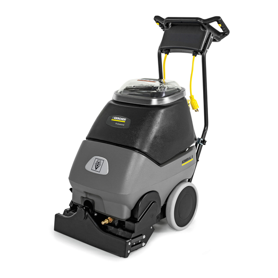
- Page 1 CARPET EXTRACTOR Operating Instructions MODEL: ADM8 10080170 Read these instructions before operating the machine 86038230 04/26/11 PRV NO. 98628...
-
Page 2: Machine Data Log/Overview
MACHINE DATA LOG/OVERVIEW Warranty Registration Thank you for purchasing a Windsor product. Warranty registration is quick and easy. Your registration will allow us to serve you better over the lifetime of the product. To register your product go to: www.windsorind.com/WarrantyRegistration.aspx... -
Page 3: Table Of Contents
TABLE OF CONTENTS Machine Data Log/Overview...1 Table of Contents...2 HOW TO USE THIS MANUAL How to use this Manual...1-1 SAFETY Important Safety Instructions ...2-1 Hazard Intensity Level...2-3 Grounding Instructions ...2-5 OPERATIONS Technical Specifications...3-1 Controls/Component Location ...3-2 Filling Operation..3-5 Operations...3-7 Cleaning Procedure. -
Page 4: How To Use This Manual
HOW TO USE THIS MANUAL This manual contains the following sections: HOW TO USE THIS MANUAL SAFETY OPERATIONS MAINTENANCE PARTS LIST The HOW TO USE THIS MANUAL section will tell you how to find important information for ordering correct repair parts. Parts may be ordered from authorized dealers. -
Page 5: Important Safety Instructions
SAFETY INSTRUCTIONS IMPORTANT SAFETY INSTRUCTIONS When using an electrical appliance, basic precaution must always be followed, including the following: READ ALL INSTRUCTIONS BEFORE USING THIS MACHINE. This machine is for commercial use. WARNING: To reduce the risk of fire, electric shock, or injury: Connect to a properly grounded outlet. - Page 6 IMPORTANTES MESURES DE SÉCURITÉ L’utilisation d’un appareil électrique demande certaines précautions: LIRE TOUTES LES INSTRUCTIONS AVANT DE FAIRE FONCTIONNER (CET APPAREIL). Cet appareil ne doit être connecter qu a des prises ayant une sortie de terre. Ne pas laisser l’appareil sans surveillance lorsqu’il est branché. Débrancher lorsque l’appareil n’est pas utilisé et avant l’entretien.
-
Page 7: Hazard Intensity Level
HAZARD INTENSITY LEVEL The following symbols are used throughout this guide as indicated in their descriptions: HAZARD INTENSITY LEVEL There are three levels of hazard intensity identified by signal words -WARNING and CAUTION and FOR SAFETY. The level of hazard intensity is determined by the following definitions: WARNING - Hazards or unsafe practices which COULD result in severe personal injury or death . - Page 8 LORS DE L’ENTRETIEN DE LA MACHINE : Éviter les parties amovibles. Ne pas porter de vêtements amples, tels que des vestes, des chemises ou des vêtements avec manches lors de l’utilisation de la machine. Utiliser les pièces détachées Windsor homologuées.
-
Page 9: Grounding Instructions
THIS PRODUCT IS FOR COMMERCIAL USE ONLY. ELECTRICAL: In the USA this machine operates on a standard 15 amp 115V, 60 hz, A.C. power circuit . The amp, hertz, and voltage are listed on the data label found on each machine. Using voltages above or below those indicated on the data label will cause serious damage to the motors. -
Page 10: Technical Specifications
TECHNICAL SPECIFICATIONS POWER TYPE ELECTRICAL: 115 V, 15 A, 60 HZ ELECTRIC VACUUM MOTOR: (1) –3 stage, 1 hp, 99 cfm (2.80 cubic meters/min.) Waterlift –117” (297cm) BRUSH: (1) 15” (38.1 cm.) SOLUTION PUMP: 100 PSI, diaphragm style, internal bypass SOLUTION CAPACITY: 8 gallons (30.3 ltr) RECOVERY CAPACITY: 8 gallons (30.3 ltr) BRUSH SPEED: 1000 rpm... -
Page 11: Controls/Component Location
CONTROLS/COMPONENT LOCATIONS 1. Main Handle. Used to pull and maneuver machine. 2. Handle Adjustment. Used to adjust height of handle. 3. Electrical Cord. 4. Solution Switch. Turns on pump. Continuous position (bottom) activates electro-valve to dispense solution to floor through jets. Intermittent position (up) requires operator to depress 1 of 3 trigger switches to dispense solution. - Page 12 CONTROLS/COMPONENT LOCATIONS 1. Solution Accessory Tool Hookup. Used for various auxiliary cleaning tools. 2. Vacuum Hose Door. Used to connect various auxiliary 1 ½ inch cleaning tool vacuum hoses. 3. Brush Height Adjustment. Used to regulate brush height from storage position to various carpet heights.
- Page 13 CONTROLS/COMPONENT LOCATIONS 1. Solution Intake Cover. 2. Vacuum Intake Cover. 3. Float Shut-Off. 4. Clean-Out Opening. 5. Pour Spout. 6. Lift Handle. ADMIRAL 86038230...
-
Page 14: Filling The Admiral
FILLING OPERATIONS RECOVERY TANK FILLING THE ADMIRAL NOTE: Use clean bucket of water to fill solution tank Do not put defoamer, solvents, spotter or prespray chemicals in the solution tank. Do not allow water to spill into vacuum motor inlet. Dry spillage from top of solution tank before replacing recovery tank. -
Page 15: Operations
SOLUTION BRUSH CONT Remove electrical cord and literature from STEP recovery tank. Fill solution tank (see filling instructions page 3-5). Plug cord into grounded outlet. Note: Be sure STEP dome is seated on recovery tank, and float shut-off is installed correctly. Adjust brush to proper setting. - Page 16 OPERATIONS Adjust handle to comfortable operating position. Tip machine back by main handle to move to starting point. Lower machine to floor. Select continuous setting to start solution spray or select intermittent setting to enable use of trigger switches to start solution spray.
-
Page 17: Cleaning Procedure
1ft. (30cm) 1in. (25mm VACUUM INTAKE COVER Start at wall closest to power outlet. Pull STEP straight back without pushing down on handle. Release intermittent trigger switches or STEP turn off continuous setting on solution switch approximately 1 foot before ending cleaning pass. - Page 18 CLEANING PROCEDURE Use right side of machine for cleaning against walls. After cleaning, turn off all controls, return brush to storage position and carefully unplug machine. To speed drying, use a Windblower™ fan. Empty recovery tank by releasing dump hose. Use a hose with cold water to clean out the recovery tank.
-
Page 19: Accessory Tool Usage
APRV NO. SOLUTION BRUSH Use only one of the following acceptable STEP accessory tools. HT – 86000610 PRV NO. 89227 DDH – 86000060 PRV NO. 89226 DH – 86031540 PRV NO. 39504 Pull back collar and insert over machine mounted fitting, then release collar to lock into place. -
Page 20: Maintenance
MAINTENANCE SERVICE SCHEDULE MAINTENANCE Check machine for cord damage Check recovery dome and gasket for damage and cleanliness Check brush – should be clean with no lint or strings attached Inspect vac shoe for blockage; remove fibers with coat hanger, etc. Check hoses for wear, blockages, or damage Check handles, switches, and knobs... -
Page 21: Periodic Maintenance
PERIODIC MAINTENANCE Twice a month, flush a white vinegar solution (One quart vinegar to two gallons of water) or anti- browning solution (mixed as directed) through the extractor. This will prevent build-up of alkaline residue in the system. If spray jets become clogged, remove the spray tips, wash them thoroughly, and blow-dry. -
Page 22: Vacuum Motor Replacement
MAINTENANCE Only qualified maintenance personnel are to perform the following repairs. VACUUM MOTOR REPLACEMENT 1. Turn off all switches and unplug machine. 2. Remove recovery tank. 3. Remove the (2) screws that fasten the solution tank to the frame, and tilt tank back to expose the inside of the frame. -
Page 23: Belt Replacement
Only qualified maintenance personnel are to perform the following repairs. Seul le personnel d'entretien qualifié peut effectuer des réparations. BELT REPLACEMENT 1. Turn off all switches and unplug machine. 2. Remove recovery tank and brush. 3. Remove the (2) screws that fasten the solution tank to the frame, and tilt tank back to expose the inside of the frame. -
Page 24: Solution Pump Replacement
MAINTENANCE Only qualified maintenance personnel are to perform the following repairs. SOLUTION PUMP REPLACEMENT Turn off all switches and unplug the machine. Remove recovery tank. Remove the (2) screws that fasten the solution tank to the frame, and tilt tank back to expose the inside of the frame. Remove solution hoses from fittings in pump. -
Page 25: Wiring Diagram
WIRING DIAGRAM 86268290 86268460 86268430 PRV NO. 88229 PRV NO. 88333 PRV NO. 88323 86266720 PRV NO. 880043 86238840 8638830 PRV NO. 41356 PRV NO. 41355 86266890 PRV NO. 88655 86238820 PRV NO. 41351 ADMIRAL 86038230... -
Page 26: Troubleshooting Chart
TROUBLESHOOTING CHART PROBLEM Is the cord plugged in. No Power, Nothing Circuit breaker tripped in building. Runs Faulty switch. Faulty power cord or pigtail. Vacuum circuit breaker tripped. Vacuum Motor Will Not Faulty main vacuum switch. Loose wiring. Faulty vac motor. Carbon brushes worn. - Page 27 NOTES: ADMIRAL 86038230...
-
Page 28: Frame Assembly
FRAME ASSEMBLY (SEE PG. 5-9) ADMIRAL 86038230 (SEE PG. 5-11) - Page 29 PART NO. PRV NO. OPEN 86003620 34341 86004340 39528 86001660 41236 86238820 41351 86239610 41354 86026150 53640 86005640 57030 86005810 57245 86198530 99809 86249430 62761 86006020 64099 86250130 66282 86250140 66288 86006580 70085 86273980 70066 OPEN 86010630 87013 86010660 87025 86010650 87018 86006550...
-
Page 30: Brush Assembly
BRUSH ASSEMBLY ADMIRAL 86038230... - Page 31 PART NO. PART NO. 86000730 03110 86227100 04084 86000900 09019 86001100 11045 86001140 12514 86001300 140343 86001310 140351 86003620 34341 86004060 36192 86004470 41345 86004980 50998 86093080 51311 86005110 51312 86005120 51314 86005130 51317 86005640 57030 86008580 57271 86249410 62758 86249420 62759 86005930...
-
Page 32: Pump Assembly
PUMP ASSEMBLY 18 1 (SEE PG. 5-11) ADMIRAL 86038230... - Page 33 PART NO. PRV NO. 86002470 22072 86002480 22090 86003470 31072 86003490 31074 86004570 44067 86241680 44073 86005640 57030 86026390 65201 86250140 66288 86274410 70195 86273750 70011 86003640 34355 86008360 78419 86026940 84160 86010810 87191 86010650 87018 86010820 87192 86005590 56014 86005580 56012 86003500...
-
Page 34: Vacuum Shoe Assembly
VACUUM SHOE ASSEMBLY ADMIRAL 86038230... - Page 35 PART NO. PRV NO. 86227350 05016 86234760 27674 86005810 57245 86006790 70351 86275120 70360 86006840 70390 86008130 73958 86010620 85039 OPEN 86010630 87013 86010700 87074 86003780 35171 86008120 73955 DESCRIPTION ARM, VAC SHOE PARALLEL COVER, ACCESSORY PORT NUT, 1/4-20 HEX NYLOCK SS SCR, 10-32 X 3/8 HHTR W/STAR SCR, 1/4-20 X.75 PPHMS PHIL SCR, 1/4-20 X 1 FHCS PLTD...
-
Page 36: Control Panel Assembly
CONTROL PANEL ASSEMBLY (SEE PG. 5-1) ADMIRAL 86038230... - Page 37 PART NO. PRV NO. 86001240 14020 86001980 14700 86230210 14832 86002010 14942 86233240 20084 86234320 23679 86003130 27823 86003140 27824 86076550 38283 86004100 38286 86004110 38287 86004790 48012 86246300 51039 86246650 51313 86005670 57040 86081530 62766 86264270 67073 86007140 72130 86087410 73180 86256240...
-
Page 38: Solution Tank Assembly
SOLUTION TANK ASSEMBLY (SEE PG. 5-1) (SEE PG. 5-1) 5-11 ADMIRAL 86038230 (SEE PG. 5-5) - Page 39 HOSE ASM, 1.5 BLK VAC X 15.5 HOUSING, VAC MOTOR VAC MOTOR ASM, CLP FAMILY BRUSH SET, 120V 5.7 VAC, AMATEK BRUSH SET, 120V VAC, WINDSOR SCR, #10 X 1.0 PPHST TYPE B TANK, ADM SOLUTION VENT, COOLING AIR SMALL WASHER, #10 X 9/16 OD STRAINER, 3/8 IN.
-
Page 40: Recovery Tank Assembly
RECOVERY TANK ASSEMBLY 5-13 ADMIRAL 86038230... - Page 41 PART NO. PRV NO. 86002400 20064 86002350 20002 86233140 20041 86008400 78499 86003110 27816 86235280 28060 86003630 34351 86003910 35230 86003930 35232 86004200 39353 86004510 41391 86004450 40019 86004500 41390 86006240 66227 86006600 70114 86032270 75260 86001370 140408 86001190 140133 86002870 27417 86242230...
-
Page 42: Suggested Spare Parts/Notes
28061 DOME ASM, CLP FAMILY 86003630 34351 FLOAT SHUT-OFF 86006240 66227 PLUG, DRAIN HOSE BRUSH SET, 120V 5.7 VAC, 86135340 14258 AMATEK 86135320 140687 BRUSH SET, 120V VAC, WINDSOR 5-15 SERIAL NO. FROM ADMIRAL 86038230 NOTES: WAS 12031 WAS 44072...