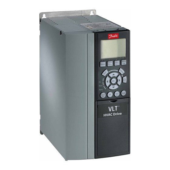
Summary of Contents for Danfoss VLT MCB 115
- Page 1 Installation Guide VLT® Programmable I/O MCB 115 VLT® HVAC Drive FC 102, VLT® Refrigeration Drive FC 103, VLT® AutomationDrive FC 301/302...
-
Page 3: Table Of Contents
Mounting the Option in Enclosure Sizes A2, A3, and B3 Mounting the Option in Enclosure Sizes A5, B1, B2, B4, C, D, E, and F Electrical Installation 3.4.1 Specifications 3.4.1.1 Programmable Inputs 3.4.1.2 Programmable Outputs 3.4.1.3 Terminals 4 Appendix Abbreviations Conventions Danfoss A/S © 2020.01 AN295938195323en-000101 / | 3... -
Page 4: Introduction
The VLT® FC Series Programming Guides provide greater detail on working with parameters. • VLT® FC Series Design Guides provide detailed capabilities and functionality to design motor control systems for various applications. Technical documentation for other product options is available at www.danfoss.com. 1.5 Product Overview 1.5.1 Intended Use ®... -
Page 5: Foreseeable Misuse
Programmable I/O MCB 115 is only functional if it is built into the drive. The option cannot be used as a standalone. 1.5.2 Foreseeable Misuse Any use not expressly approved by Danfoss constitutes misuse. This also applies to failure to comply with the specified operating conditions and applications. -
Page 6: Safety
Have read and understood the safety guidelines given in this manual and also the instructions given in the operating guide of the drive. • Have good knowledge of the generic and specialist standards applicable to the specific application. 6 | Danfoss A/S © 2020.01 AN295938195323en-000101 / 130R0655... -
Page 7: Safety Precautions
This document gives important information on how to prevent injury and damage to the equipment or the system. Ignoring them can lead to death, serious injury, or severe damage to the equipment. Make sure to fully understand the dangers and safety measures incurred in the application. Danfoss A/S © 2020.01 AN295938195323en-000101 / 130R0655| 7... -
Page 8: Installation
3.2 Mounting the Option in Enclosure Sizes A2, A3, and B3 Context: The installation procedure depends on the enclosure size of the drive. This procedure is for installation in enclosure sizes A2, A3, and 8 | Danfoss A/S © 2020.01 AN295938195323en-000101 / 130R0655... -
Page 9: Mounting The Option In Enclosure Sizes A5, B1, B2, B4, C, D, E, And F
3.3 Mounting the Option in Enclosure Sizes A5, B1, B2, B4, C, D, E, and F Context: The installation procedure depends on the enclosure size of the drive. This procedure is for installation in enclosure sizes A5, B1, B2, B4, C, D, E, and F. Danfoss A/S © 2020.01 AN295938195323en-000101 / 130R0655| 9... -
Page 10: Electrical Installation
Installation in Enclosure Sizes A5, B1, B2, B4, C, D, E, and F 3.4 Electrical Installation 3.4.1 Specifications The VLT® Programmable I/O MCB 115 has 3 programmable inputs/outputs, which extend the number of inputs and outputs for the drive. 10 | Danfoss A/S © 2020.01 AN295938195323en-000101 / 130R0655... -
Page 11: Programmable Inputs
Used as analog voltage Used as current input input input Number of inputs Terminal X49/1–6 X49/1–6 X49/1–6 Voltage/current range – 0–10 V DC or 2–10 V DC 0–20 mA or 4–20 mA Danfoss A/S © 2020.01 AN295938195323en-000101 / 130R0655| 11... -
Page 12: Programmable Outputs
Maximum output current: 24 mA Accuracy – Better than ±1% Better than ±1% Resolution [bits] – Maximum load – ±28 V continuously ±29 mA continuously Load impedance – ≥10 kΩ ≤200 Ω 12 | Danfoss A/S © 2020.01 AN295938195323en-000101 / 130R0655... -
Page 13: Terminals
There are 3 inputs and 3 outputs on the option: • Inputs: X49/1+2, X49/3+4, and X49/5+6 • Outputs: X49/7+8, X49/9+10, and X49/11+12 MCB 115 OPTION B Programmable I/O 130B1266 SW. ver. xx.xx X49/ 10 11 12 Illustration 4: Terminal X49 Danfoss A/S © 2020.01 AN295938195323en-000101 / 130R0655| 13... -
Page 14: Appendix
Parameter name. Parameter option. Parameter group name. • All dimensions in drawings are in metric values (imperial values in brackets). • An asterisk (*) indicates the default setting of a parameter. 14 | Danfoss A/S © 2020.01 AN295938195323en-000101 / 130R0655... - Page 15 Installation Guide | VLT® Programmable I/O MCB 115 Danfoss A/S © 2020.01 AN295938195323en-000101 / 130R0655| 15...
-
Page 16: An295938195323En-000101
Danfoss can accept no responsibility for possible errors in catalogues, brochures and other printed material. Danfoss reserves the right to alter its products without notice. This also applies to products already on order provided that such alterations can be made without subsequential changes being necessary in specifications already agreed. All trademarks in this material are property of the respective companies.


