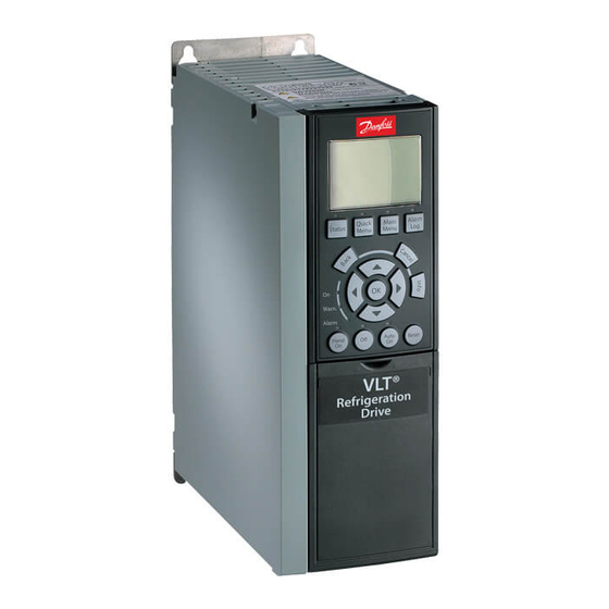
Danfoss VLT Series FC 102 Installation Manual
Frequency converter
Hide thumbs
Also See for VLT Series FC 102:
- Programming manual (322 pages) ,
- Design manual (254 pages) ,
- Operating manual (200 pages)
Summary of Contents for Danfoss VLT Series FC 102
-
Page 1: Installation Guide
MAKING MODERN LIVING POSSIBLE Installation Guide ® PROFINET MCA 120 ® Frequency Converter Series FC 102 • FC 103 • FC 202 FC 301/302 www.danfoss.com/drives... -
Page 3: Table Of Contents
3.9 Reassembling Cover 3.10 Applying Power 3.11 Checking Network Cabling 4 Troubleshooting 4.1 Warnings and Alarms 4.2 Troubleshooting 4.2.1 LED Status 4.2.2 No Communication with the Frequency Converter 4.2.3 Warning 34 Appears Index MG90U402 Danfoss A/S © Rev. 07/2014 All rights reserved. -
Page 4: Introduction
Strain relief (only for A1 and A2 enclosures) from Danfoss. See www.danfoss.com/BusinessAreas/DrivesSo- • Installation Guide lutions/Documentations/VLT+Technical+Documentation.htm for listings. 1.4 Approvals and Certifications More approvals and certifications are available. For more information, contact a local partner. Danfoss A/S © Rev. 07/2014 All rights reserved. MG90U402... -
Page 5: Disposal
Programmable logic control Table 1.1 Symbols and Abbreviations Conventions Numbered lists indicate procedures. Bullet lists indicate other information and description of illustrations. Italicised text indicates: • Cross reference • Link • Parameter name MG90U402 Danfoss A/S © Rev. 07/2014 All rights reserved. -
Page 6: Safety
Operating or serious injury. Instructions, Chapter 2 Safety. • Installation, start-up, and maintenance must be performed by qualified personnel only. Danfoss A/S © Rev. 07/2014 All rights reserved. MG90U402... - Page 7 An internal failure in the frequency converter can result in serious injury, when the frequency converter is not properly closed. • Ensure that all safety covers are in place and securely fastened before applying power. MG90U402 Danfoss A/S © Rev. 07/2014 All rights reserved.
-
Page 8: Installation
..Signal M12 PIN# RJ 45 RX + LCP cradle TX + Fieldbus option RX - TX - Illustration 3.1 Exploded View Illustration 3.3 PROFINET Connectors Danfoss A/S © Rev. 07/2014 All rights reserved. MG90U402... -
Page 9: Emc-Compliant Installation
500 mm (20 in). NOTICE When the fieldbus cable crosses a motor cable or a brake resistor cable, ensure that the cables cross at an angle of 90°. MG90U402 Danfoss A/S © Rev. 07/2014 All rights reserved. -
Page 10: Topology
Numbers of frequency converters Minimum update time [ms] connected in series <8 8-16 17-32 33-50 >50 not recommended Illustration 3.7 Ring/Redundant Line Topology Table 3.1 Minimum Update Time Danfoss A/S © Rev. 07/2014 All rights reserved. MG90U402... -
Page 11: Setting Address Switches
Table 3.2 Host Names Setting (FC 302 used in this example) The station name change comes into effect at the next power-up. Read the station name in 12-08 Host Name. Illustration 3.8 Recommended Design Rules MG90U402 Danfoss A/S © Rev. 07/2014 All rights reserved. -
Page 12: Electrical Installation
Table 3.3 Cable Specifications for Application Types A, B and C Relevant standard ISO/IEC 11801 Edition 2.0, IEC 61156 (minimum Category 5) ≤20 ns/100 m Delay skew ≤50 m Ω/m at 10 MHz Transfer impedance Table 3.4 Transmission Performance Requirements Danfoss A/S © Rev. 07/2014 All rights reserved. MG90U402... - Page 13 MS 1 MA C-0 0-1 MS 2 B-0 8-0 0-0 0-2 2 SW .ve r. Illustration 3.11 Wiring for Enclosure Types A4-A5, B1-B4, and C1-C4 Illustration 3.10 Wiring for Enclosure Types A1-A3 MG90U402 Danfoss A/S © Rev. 07/2014 All rights reserved.
-
Page 14: Reassembling Cover
Illustration 3.12 Wiring for Enclosure Types D, E, and F NOTICE Do not strip the Ethernet cable. Do not ground it via the strain relief plate. Ground the screened Ethernet cables through the RJ 45 connector on the PROFINET interface. Danfoss A/S © Rev. 07/2014 All rights reserved. MG90U402... -
Page 15: Troubleshooting
No communication to PROFINET module. Module is waiting for a configu- Green: ration telegram from the controller. IO AR established Green: Supervisor AR established, No IO AR. Green: ▂███▂███▂█ ▂█▂█▂█▂█▂█ Internal error Red: Yellow: ▂█▂█▂█▂█▂█ Wink Table 4.3 MS: Module Status MG90U402 Danfoss A/S © Rev. 07/2014 All rights reserved. -
Page 16: No Communication With The Frequency Converter
Check 2: Does the hardware configuration match? Check that the hardware configuration matches the value in 12-08 Host Name. Check 3: Is the correct GSD file installed? Download the correct GSD file from www.danfoss.com/BusinessAreas/DrivesSolutions/. Danfoss A/S © Rev. 07/2014 All rights reserved. MG90U402... -
Page 17: Index
Wiring procedure................. 11 High voltage..................... 4 Host name....................9 Intended use..................... 2 Items supplied..................2 Leakage current..................5 LED....................... 3 Line topology................... 8 Load sharing..................... 4 Module status..................13 Motor wiring..................... 7 MG90U402 Danfoss A/S © Rev. 07/2014 All rights reserved. - Page 18 Danfoss can accept no responsibility for possible errors in catalogues, brochures and other printed material. Danfoss reserves the right to alter its products without notice. This also applies to products already on order provided that such alterations can be made without subsequential changes being necessary in specifications already agreed. All trademarks in this material are property of the respective companies.


