Table of Contents
Advertisement
Quick Links
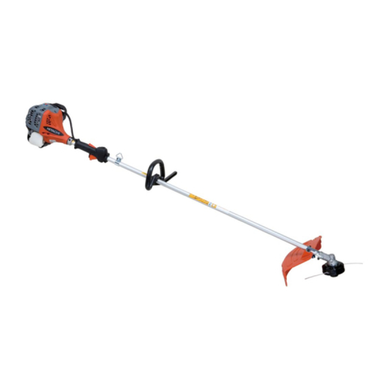
PRODUCT NAME
Hitachi Engine Grass Trimmer
CG 25EUS (L)
Models
CG 25EUS
MARKETING OBJECTIVE
The newly released CG 25EUS Engine Grass Trimmer is Hitachi Koki group first tool equipped with a small four-
cycle engine. There is now a growing need for tools equipped with a small, low-exhaust four-cycle engine as
environmentally friendly products.
With the new Model CG 25EUS, we aim to enhance the market share of Hitachi's engine grass trimmer series.
APPLICATIONS
Cutting grass:
• Cutting grass in fields
• Cutting undergrowth in orchards
• Cutting other general kinds of grass
SELLING POINTS
[ NEW FEATURES ]
Small OHV Four-stroke Engine
Lightest weight in its Class
Smallest engine in its Class
SPECIFICATIONS AND PARTS ARE SUBJECT TO CHANGE FOR IMPROVEMENT.
LIST Nos.
CG 25EUS : E071
May. 2010
CG 25EUS (L)
Sales Division
C
Advertisement
Table of Contents

Related Manuals for Hitachi Koki CG 25EUS


Summary of Contents for Hitachi Koki CG 25EUS
- Page 1 CG 25EUS MARKETING OBJECTIVE The newly released CG 25EUS Engine Grass Trimmer is Hitachi Koki group first tool equipped with a small four- cycle engine. There is now a growing need for tools equipped with a small, low-exhaust four-cycle engine as environmentally friendly products.
- Page 2 REMARK: • For more information about HANDLING INSTRUCTIONS, visit our website at: http://www.hitachi-koki.com/manual_view_export/ • Throughout this TECHNICAL DATA AND SERVICE MANUAL, a symbol(s) is(are) used in the place of company name(s) and model name(s) of our competitor(s). The symbol(s) utilized here is(are) as follows: Competitors Symbols Utilized Company Name...
-
Page 3: Table Of Contents
2. Specific Instructions for Customers -------------------------------------------------------------------------- 5 TROUBLESHOOTING GUIDE --------------------------------------------------------------------------------------------- 6 REPAIR GUIDE ----------------------------------------------------------------------------------------------------------------- 8 1. Precautions on Maintenance, Inspection and Repair --------------------------------------------------- 8 2. Inspection Criteria for Each Section and Consumable Parts ----------------------------------------- 8 Assembly Diagram for CG 25EUS... -
Page 4: Selling Points
The Model CG 25EUS comes equipped with the first small four-cycle engine among grass trimmers produced by the Hitachi Koki group. Thanks to the use of this four-cycle engine with low gas emissions, the Model CG 25EUS complies with secondary exhaust regulations in Europe and the USA. -
Page 5: Specifications
SPECIFICATIONS Model CG 25EUS (L) CG 25EUS Engine type Forced air-cooling, four-cycle OHV engine (type F25) Engine displacement 25 mL Cylinder size Ф 35 x 26 mm (inner diameter x stroke) Max. power output 0.81 kW (1.1 hp) / 7,500 min Max. -
Page 6: Comparison With Similar Products
COMPARISONS WITH SIMILAR PRODUCTS (Superior specifications: Maker HITACHI Model CG 25EUS (L) Forced air-cooling Forced air-cooling Forced air-cooling Engine type – four-cycle OHV four-cycle OHC four-cycle OHV Engine 24.5 displacement Max. power output 0.81 (1.1 hp) 0.81 (1.1 hp) 0.7 (0.9 hp) Other than U. -
Page 7: Precautions On Sales Promotion
PRECAUTIONS ON SALES PROMOTION 1.Safety Instructions In the interest of promoting the safest and most efficient use of the Model CG 25EUS Engine Grass Trimmer by all of our customers, it is very important when concluding a sale that the salesperson carefully ensure that the customer seriously recognizes the importance of the Handling Instructions and precautions indicated on the Caution Plate and Name Plate attached on the product. -
Page 8: Specific Instructions For Customers
2. Specific Instructions for Customers (1) Proper startup and stopping procedures Thoroughly instruct the customer on how to start and stop this tool. With regard to startup, make sure that the customer fully understands the difference in startup procedure between two situations when the engine is cold and when it has been warmed up. -
Page 9: Troubleshooting Guide
TROUBLESHOOTING GUIDE Situation Cause Measure The piston ring is stuck. Disassemble the engine and The connecting rod bearing is replace the faulty part Starter handle stuck The crankshaft does cannot be not rotate A valve is damaged Replace the faulty part pulled The crank gear or cam gear is Replace the faulty part... - Page 10 Situation Cause Measure The fuel filter is clogged Clean or replace the part The engine stalls Loose nuts Repair the parts Worn push rod Valve Worn valve clearance is Worn pivot Replace the faulty part extended Starts, but when Worn rocker arm it accelerates…...
-
Page 11: Repair Guide
• After repair, check whether the throttle lever returns to the idling position and the engine stops when you set the stop switch to the stopping position. 2. Inspection Criteria for Each Section and Consumable Parts Item CG 25EUS Idling speed 2,500 to 3,500 Max. no-load revolution (with cutter... - Page 12 Repair Flowchart Piston ring is damaged Replacement Pull the starter handle. Piston or cylinder is stuck Replacement Check whether there is compression and the handle ca Needle bearing on connecting rod is damaged Replacement be pulled Ball bearing is stuck Replacement Inspection and Magneto rotor touches the ignition coil...
- Page 13 Check that the engine speed increases by pulling the throttle lever Cylinder exhaust port or muffler is Cleaning The speed does clogged with carbon not increase Cleaner element is clogged Cleaning Inspection and Valve clearance is extended adjustment Carbon accumulated on a sealed valve Cleaning surface Check whether the speed...
- Page 14 Repair Procedures [Bold] numbers in the descriptions below correspond to item numbers in the Parts List and exploded view assembly diagram for the Model CS 25EUS. Be sure to stop the engine before disassembly. 1. How to check for sparks by the spark plug ●Spark plug CAUTION: •...
- Page 15 3. Electric Wiring ● Electric Wiring The figure on the right shows the electric wiring. (1) Connect the Stop Cord [141] to the Ignition Coil Spark Plug Cap [20] Set [140], and then connect the Earth Cord [143] to the Ignition Coil Set [140] with the Hex. Hole Bolt M4 x 18/WS [139].
- Page 16 5. Adjusting the Valve Clearance CAUTION: • Be sure to adjust the valve clearance with the engine sufficiently cooled down. (1) Remove the two Tapping Screw D4.5 x 16 [128] and upper Seal Lock Screw M4 [88] fixing the Recoil Starter Body Assy [80], and then remove the Engine Cover [129].
- Page 17 Disassembly and Reassembly 1. Fan Case Ass’y (A) Disassembly: Remove Hex. Socket HD. Bolt (W/SP. Washer) M5 x 20 [168] and Tapping Screw D4.5 x 16 [128], and then remove the Fan Case [146]. Next, remove the Pipe Holder A [124], Anti Vibe Rubber (A) [123], Pipe Holder B [125], and Anti Vibe Rubber (B) [126] in this order.
- Page 18 2. Muffler Ass’y Disassembly: Loosen Hex. Socket HD. Bolt M5 [11], and then remove the Muffler [12], Muffler Gasket (A) [13], Wind Guide Plate (B) [14], and Muffler Cover (A) [15]. Reassembly: Wipe off any carbon from the exhaust inlet and outlet of the Muffler [12], and then mount the removed parts in the order shown in the figure below.
- Page 19 3. Cleaner, Carburetor and Insulator Disassembly: Loosen the Cover Fixing Bolt [104], and then remove the Cleaner Cover [103] and Cleaner Element [102]. Loosen Machine Screw (W/SP. Washer) M5 [99], and then remove the Cleaner Body [94], Carburetor [32], and other parts. Loosen Machine Screw (W/Washers) M5 x 30 [26], and then remove the Insulator [25] and other parts.
- Page 20 4. Ignition Coil and Spark Plug Cap Disassembly: Loosen Hex. Hole Bolt M4 x 18/WS [139], and then remove the Ignition Coil Set [140]. To remove the Spark Plug Cap [20], add a drop of oil into the Spark Plug (NGK CMR5H) [22] hole in the Spark Plug Cap [20], move the high-voltage cord back and forth to spread the oil, and then slowly pull out the Metal Fitting of Plug Cap [21] so that it is not extended.
- Page 21 6. Starter pulley Ass’y, Clutch Ass’y and Magneto Rotor Disassembly: To remove the Starter Pulley Ass’y [93], lightly hit the Starter Pulley Ass’y [93] to turn it counterclockwise while holding the Magnet Rotor [138]. To remove the Clutch [134], loosen the two Step Bolt [131]. To remove the Magnet Rotor [138], remove the Flywheel Nut [136], and then use the special magnet rotor assembly remover to pull out the Magnet Rotor [138].
- Page 22 7. Cylinder, Rocker Arm and Valve Disassembly: Loosen three Machine Screw (W/SP. Washer) M4 x 10 [1], and then remove the Cylinder Head Cover [2]. If the Cylinder Head Cover [2] cannot be easily removed, use a plastic hammer to lightly hit the side of the Cylinder Head Cover [2].
- Page 23 ●Cylinder, Rocker Arm and Valve Retainer Valve [16] Valve Spring [17] Machine Screw Stem Seal Base [18] (W/SP. Washer) M4 x 10 [1] Stem Seal [19] Cylinder Head Cover [2] Cylinder (A) [47] Lock Nut M5 [3] Pivot Rocker Arm [4] Rocker Arm [8] Shaft Bolt [9] Intake Valve [49]...
- Page 24 8. Piston and Piston Ring Disassembly: Use long-nose pliers to remove the Piston Pin Circlip [61], pull out the Piston Pin [66], and then remove the Piston [60]. Remove the 1st Ring [57] and 2nd Ring [58] while opening their slits. The Oil Ring [59] consists of one expander and two scrapers.
- Page 25 9. Crank Case Ass’y Disassembly: Loosen the three Machine Screw (W/SP. Washer) M5 x 16 (Black) [56], and then remove the Cover Pump [55], Inner Rotor [53], Outer Rotor [54], and Base Pump [52]. Loosen the six Hex. Hole Bolt M4 x 18/WS [79], disassemble Crank Case Ass’y (B) [73], and then remove the Crank Shaft Gear Set [65] and Cam Shaft set [68].
- Page 26 Screw Tightening Torque Units : N•m {kgf•cm} Location Quantity Dimension Tightening torque Pump Filter Body [159] Seal Lock Screw M4 [88] 2.0 to 3.0 {20.4 to 30.6} Recoil Starter Starter Pulley Ass’y [93] 9 to 12 {91.8 to 122.4} Hex. Hole Bolt Ignition Coil Set [140] 2.5 to 4.5 {25.5 to 45.9} M4 x 18/WS [139]...
- Page 27 LIST NO.E071 ENGINE 2010・4・9 ENGINE GRASS TRIMMER Model CG 25EUS (E1)
- Page 28 CG 25EUS - 2 - 4 - 10...
- Page 29 CG 25EUS 4 - 10 - 3 -...
- Page 30 PARTS CG 25EUS ITEM CODE NO. DESCRIPTION REMARKS USED 307-635 MACHINE SCREW (W/SP. WASHER) M4 X 10 669-6440 CYLINDER HEAD COVER 949-566 LOCK NUT M5 (10 PCS.) 669-6438 PIVOT ROCKER ARM 669-6437 PUSH ROD 669-6432 TAPPET 669-6442 BREATHER PIPE 669-6439 ROCKER ARM...
- Page 31 PARTS CG 25EUS ITEM CODE NO. USED 669-6416 EXHAUST VALVE 669-6444 PUMP GASKET 669-6443 BASE PUMP 669-6445 INNER ROTOR 669-6446 OUTER ROTOR 669-6447 COVER PUMP 696-997 MACHINE SCREW (W/SP. WASHER) M5 X 16(BLACK 669-6429 1ST RING 669-6430 2ND RING 669-6431 OIL RING...
- Page 32 PARTS CG 25EUS ITEM CODE NO. USED 669-6962 FUEL PIPE 668-5139 PRIMING PUMP COMP. 669-6459 CLEANER ELEMENT 669-6458 CLEANER COVER 668-4655 COVER FIXING BOLT 668-5408 WASHER 5 668-5408 WASHER 5 949-566 LOCK NUT M5 (10 PCS.) 668-4667 HEX. HOLE BOLT M5 X 12/S 305-583 HEX.
- Page 33 PARTS CG 25EUS ITEM CODE NO. DESCRIPTION REMARKS USED 669-6968 THROTTLE WIRE (USA) FOR USA (L), CAN (L) 669-6474 TANK 669-6969 TANK (USA) FOR USA (L), CAN (L) 668-5199 PUMP FILTER BODY 669-6477 STAND 669-6478 COLLAR 668-4709 HEX. HOLE BOLT M5 X 25/S...
- Page 34 PARTS CG 25EUS ITEM CODE NO. DESCRIPTION REMARKS USED SCREW (W/SPRING WASHER) M5 HEX. BOLT M5 X 30 PINION BALL BEARING 609Z GRIP RING D9 C-RING D24 669-6494 COVER BRACKET EXCEPT FOR USA (L), CAN (L) 668-4714 HEX. HOLE BUTTON SCREW 6 X 25S EXCEPT FOR USA (L), CAN (L) 668-5064 HEX.
- Page 35 STANDARD ACCESSORIES CG 25EUS ITEM CODE NO. DESCRIPTION REMARKS USED 669-6457 BOX WRENCH (HEX. SOCKET 16/17MM) 668-4766 WRENCH 8 X 10 EXCEPT FOR USA (L), CAN (L) 944-458 HEX. BAR WRENCH 4MM 668-4768 CUTTER COVER EXCEPT FOR USA (L), CAN (L)
- Page 36 CG 25EUS ITEM CODE NO. DESCRIPTION REMARKS USED - 10 - Printed in Japan 4 - 10 *ALTERNATIVE PARTS (100409N)