Table of Contents
Advertisement
Advertisement
Table of Contents

Related Manuals for Husqvarna K 750


Summary of Contents for Husqvarna K 750
- Page 1 Workshop manual K 750 HUSQVARNA CONSTRUCTION PRODUCTS...
-
Page 2: Table Of Contents
CONTENTS Page HUSQVARNA LITERATURE 2. SPECIAL FUNCTIONAL COMPONENTS K 750 COMPONENTS – ORIENTATION 4. DISMANTLING INTO BASIC MODULES 5. STARTER 6. IGNITION SYSTEM 7. FLYWHEEL 8. AIR FILTER 9. FUEL SYSTEM 10. CARBURETTOR 11. DECOMPRESSION VALVE 12. CYLINDER/PISTON 13. CRANKCASE 14. - Page 3 This arrangement means that as a mechanic, Workshop manual K 750 at least until you have learnt the basic composi- tion of the machine, you need to start with the HUSQVARNA CONSTRUCTION PRODUCTS chapter “Dismantling into Basic Modules”...
-
Page 4: Special Functional Components
SPECIAL FUNCTIONAL COMPONENTS New technical solutions Husqvarna K750 is the first model in a new generation of power cutters with a number of new technical solutions: New engine technology – Dual Charge The cylinder, piston and carburettor are radically changed. -
Page 5: Components - Orientation
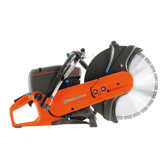
COMPONENTS – ORIENTATION Components 1. Cutting blade 2. Blade guard 3. Adjustable handle for the blade guard 4. Front handle 5. Air filter cover 6. Cylinder cover 7. Starter handle 8. Starter 9. Combination spanner 10. Belt adjustment screw 11. Lock screws for belt adjustment 12. -
Page 6: Dismantling Into Basic Modules
DISMANTLING INTO BASIC MODULES Basic modules This chapter shows how the machine is built up of basic modules, for example, the starter, carburettor, air filter system, etc. The purpose is to illustrate how you can easily and effectively dismantle and assemble the machine in its basic modules. - Page 7 DISMANTLING INTO BASIC MODULES Air filter 1. Loosen the three screws on the air filter cover and remove the cover. 2. Lift off the filter base. 3. Carefully lift up the paper filter so that the dust does not fall down onto the service filter.
- Page 8 DISMANTLING INTO BASIC MODULES Assembly 5. Hook the throttle rod into the valve arm as illustrated. Lift the carburettor unit into position and fit the fuel hose. Press down the throttle rod into throttle control with the help of a pair of pliers. 6.
-
Page 9: Starter
DISMANTLING INTO BASIC MODULES 3. Dismantle the three screws on the air duct cover. 4. Lift off the air duct cover. Muffler Dismantle the cutting head and the starter. 1. Dismantle the four screws on the muffler. 2. Dismantle the muffler. Fit the gaskets correctly! 3. - Page 10 STARTER Replacing the starter Replacing the starter cord cord Dismantle the starter. Dismantle the starter. Eliminate the spring force from the return spring Eliminate the spring force 1. Pull out the starter cord approximately from the return spring 12 in./30 cm. Hold the starter pulley 1.
- Page 11 STARTER Starter pulley Dismantle the centre bolt and lift off the starter pulley. Clean the surfaces between the starter pulley and the spring cassette. Assembly Lubricate the hub with grease (arrows). Preferably also apply some grease around the starter pulley hub so that the grease seals against the spring cassette.
- Page 12 STARTER Starter pawls Function In principle the starter pawls have two positions that are determined by the centrifugal force generated by the rotation of the flywheel. When the engine is at a standstill the springs push the starter pawls towards the centre, which when starting then grip the starter pulley's metal sleeve.
-
Page 13: Ignition System
It is insensitive to moisture and dirt. The design is point such that the ignition point does not need to readjustment. Husqvarna K750 has integrated overspeed protection in the electronic unit that limits the engine's speed to 9,300 rpm. The ignition system consists of the primary coil (A) and secondary coil (B) which are both surround ed by the iron core (C). - Page 14 IGNITION SYSTEM Trouble shooting Trouble shooting Examine the ignition system Examine the ignition system first when first when the engine does not the engine does not start. start. Check the ignition spark Check the ignition spark Earth the spark plug against the cylinder Earth the spark plug against the by using the spark plug socket to extend cylinder by using the spark plug...
- Page 15 IGNITION SYSTEM Test with a test lamp Test with a test lamp Connect a battery in series with Connect a battery in series with a test a test lamp to the short-circuit lamp to the short-circuit cable respective cable respective engine body. engine body.
-
Page 16: Flywheel
Tool 502 51 49-02 Tool 502 51 49-02 502 51 49-02 The special tool is used to A special tool from Husqvarna is dismantle and assemble the required to dismantle and assemble the flywheel. flywheel. The tool fits virtual all fly - wheels on Husqvarna power cutters. - Page 17 FLYWHEEL Check the keyway and key Check the keyway and key Note that the key in the flywheel Note that the key in the flywheel is cast is cast and can not be replaced. and can not be replaced. If the key is If the key is damaged the fly- damaged the flywheel must be replaced.
-
Page 18: Air Filter
AIR FILTER Function Husqvarna Active Air Filtration is a filter system that effectively purifies the air to the engine in three separate steps and according to three different purification principles: 1. Centrifugal cleaning is the first step in the purification of the inlet air. - Page 19 FUEL SYSTEM Fuel filter Fuel filter Dismantle the filler cap. Dismantle the filler cap and pull out the section holding the filler cap in position Catch the fuel hose with the when fuelling. help of tool 502 50 83-01. Catch the fuel hose with the help of tool 502 50 83-01.
-
Page 20: Fuel System
FUEL SYSTEM Exclude the carburettor as Exclude the carburettor as the the cause of the leakage cause of the leakage Dismantle the carburettor unit. Dismantle the carburettor unit. Plug Plug the hose by the carburettor the hose by the carburettor and redo the and redo the pressure test. - Page 21 FUEL SYSTEM Press up the air vent unit with a Press up the air vent unit with a pair of pair of pliers. pliers. Filter – functional test Filter – functional test Pull off the rubber hose with Pull off the rubber hose with the sintered the sintered filter.
-
Page 22: Carburettor
CARBURETTOR Carburettor unit Carburettor unit Dismantling Dismantling Pull up the service filter and put Pull up the service filter and put it to it to one side so that it is not one side so that it is not damaged. damaged. - Page 23 CARBURETTOR Support insert Later versions of the K750 are fitted as standard with a support insert in the rubber guide for the fuel-air mixture. The support insert ensures the guide is properly seated in the metal plate. Supplementing older machines It is recommended that this support insert also be fitted to older machines when they are serviced.
- Page 24 CARBURETTOR Components 1. Throttle valve 2. Air valve 3. Choke valve 4. Pulse line, to the carburettor's pump diaphragm 5. Fuel line 6. High and low speed jet (set at the factory) 7. Idle screw, speed adjustment 8. Throttle rod for the choke 9.
- Page 25 CARBURETTOR Functional test Functional test Pressure tester Pressure tester 501 56 27-01 501 56 27-01 The pressure tester has a pump piston The pump is operated with one that is operated with one hand. hand. The pressure tester is supplied with an The pressure tester is sup plied adapter nipple for small sizes.
- Page 26 CARBURETTOR Metering unit Fuel chamber Note the interrelated positions of the components when dismantling, as they can be reassembled in the wrong order. The gaskets A are identical. Measurement chamber Measurement chamber diaphragm diaphragm The air volume above the diaphragm acts Make a visual inspection of the as an air spring and is a pre requisite for diaphragm with regard to cracks...
- Page 27 CARBURETTOR Pump unit Pump unit Function Function The pump diaphragm (A) is The pump diaphragm (A) is driven by driven by the pressure variations the pressure variations in the crankcase in the crankcase. that are led to the pulse line on the The fuel on the underside of pump unit cover.
- Page 28 CARBURETTOR Valve axles Valve axles Check that there is no radial play Leakage from the valve axles results in on the valve axles. Replace parts incorrect fuel/air mixture and to dust if necessary. penetration in the engine. Check that there is no radial play on the valve axles.
-
Page 29: Decompression Valve
DECOMPRESSION VALVE Decompression valve Function The decompression valve reduces the compression in the cylinder when starting. A limited quantity of fuel/air mixture leaks out through the decompression valve, as shown in fig. A. As soon as the engine fires the valve will close due to the combustion pressure, as in fig. -
Page 30: Cylinder/Piston
CYLINDER/PISTON Compression test Compression test The test indicates leakage from The compression test indicates leakage the combustion chamber. from the combustion chamber. If the Close the decompression machine lacks engine power and is dif- valve or fit the sealing plug ficult to start this may be due to poor 503 55 22-01. - Page 31 CYLINDER/PISTON Remove the cylinder base gasket. Remove the cylinder base gasket. Tool kit 502 50 70-01 Tool kit 502 50 70-01 The tool kit contains piston The tool kit contains, to the left, piston ring compressors, a piston stop, ring compressors to press together the and a support plate for the piston rings when assembling.
- Page 32 CYLINDER/PISTON Gudgeon pin punch Gudgeon pin punch 505 38 17-05 Used to dismantle and assemble The gudgeon pin punch is used to press the gudgeon pin. out the gudgeon pin. It is also used for assembly. 505 38 17-05 Dismantle the gudgeon pin Dismantle the gudgeon pin Push out the gudgeon pin by Push out the gudgeon pin in any direc-...
- Page 33 CYLINDER/PISTON Wear tolerances Wear tolerances Cylinder Cylinder Inspect the cylinder bore against Inspect the cylinder bore against the the light. As long as the surface light. As long as the surface layer has not layer has not been broken been broken through, the cylinder is in through, the cylinder is in working order.
- Page 34 CYLINDER/PISTON Piston damage The cause of engine failure is often difficult to establish, primarily when the machine's history is not known The typical cases below can provide some guidance. Normal wear Typical normal wear is easiest to see on the piston sections that face the exhaust and inlet sides.
- Page 35 CYLINDER/PISTON Assembly Assembly Oil in Oil in New or cleaned bearings and New or cleaned bearings and piston rings piston rings should be oiled in should be oiled in with 2-stroke oil before with 2-stroke oil before assembly. assembly to initially ensure satisfactory lubrication.
-
Page 36: Crankcase
CRANKCASE Leakage test A leaking crankcase results in reduced crankcase compression. A typical sign is that the machine is difficult to start. Tools 544 10 33-01 The tool kit 544 10 33-01 consists of parts for sealing the cylinder's exhaust and inlet ports as well as a sealing plug that replaces the decompression valve. - Page 37 CRANKCASE Crankcase seals Tools The puller 504 91 40-01, assembly taper 505 38 17-23 and the assembly punch 502 50 82-01 are needed to change the crankcase sealing rings. 504 91 40-01 505 38 17-23 502 50 82-01 Dismantling 1. Press down the puller and tighten the puller's conical thread in the seal ing ring.
- Page 38 Tools A universal puller and a special A universal puller (504 90 90-02) and a tool are needed to spilt the special tool (grip plate) from Husqvarna crankcase. (544 06 00-02) are needed to spilt the crankcase. 504 90 90-02...
- Page 39 CRANKCASE If the bearing releases from the crankcase 531 00 48-67 Normally the bearing should release from the crankshaft during dismantling. The bearing is dismantled from the crankshaft using the puller 531 00 48-67. 1. First fit the puller plate behind the bearing. Exercise care so that the plastic components on the balance weights are not damaged, see “IMPORTANT!”...
- Page 40 CRANKCASE Crankshaft Tools Use the tool kit 544 10 36-02 to press the crankshaft into the bearing, after first fitting this in the relevant crankcase half. The threaded mandrel for the clutch and flywheel side is M10V and M8x1, respec- tively.
- Page 41 CLUTCH Dismantling Dismantling Dismantle the cutting head, the Dismantle the cutting head, the rear belt rear belt guard, the air filter guard, the air filter cover, and the filter cover, and the filter base. base. Fit the piston stop Fit the piston stop Lock the crankshaft's travel with Lock the crankshaft's travel by fitting the the piston stop 504 91 06-05.
-
Page 42: Clutch
CLUTCH Clutch springs Clutch springs Dismantling/assembling Dismantling/assembling Position a large Phillips screw - The clutch springs can be dismantled driver in each spring eye and and assembled with the following tool hold the screw drivers. arrangement: Position a large Phillips Expand the spring using cir - screwdriver in each spring eye and hold clip pliers between screwdriver... - Page 43 Bearing replacement – needle bearing For a long time, a clutch drum with needle bearing has been the standard design on Husqvarna petrol-driven power cutters. The needle bearing is lubricated via a channel in the crankshaft from the crankcase. In 2007 the needle bearing is being replaced with a ball bearing. Please note that machines with a needle bearing cannot be fitted with a ball bearing as the crankshaft and clutch drum are of different dimensions.
- Page 44 CLUTCH Bearing replacement – ball bearing A clutch drum with permanently lubricated ball bearing is being introduced on the K750 in 2007. The drilled channel in the crankshaft that provided the earlier needle bearing design with lubrication is being discontinued. Tools The tool kit 504 56 79-01 is needed to replace the ball bearing of the clutch drum.
-
Page 45: Cutting Head
CUTTING HEAD Dismantling Dismantling Dismantle the cutting head Dismantle the cutting head from the from the machine. machine. This chapter describes dismantling of the cutting head components and has instructions for replacing the blade shaft bearing at the end. Lock the belt pulley with a Lock the belt pulley with a mandrel and mandrel and dismantle the dismantle the centre screw. - Page 46 CUTTING HEAD Lift the blade guard off the Lift the blade guard off the bearing bearing housing. housing. Check that the gear rings for the Check that the gear rings for the blade blade guard's locking mechanism guard's locking mechanism are intact. are intact.
- Page 47 CUTTING HEAD Place the triangle of the special Place the triangle of the special tool in tool in the cut-out of the bearing the cut-out of the bearing housing inten- housing intended for it. ded for it. Knock out the entire bearing Knock out the entire bearing unit with a unit with a plastic hammer, plastic hammer.
- Page 48 CUTTING HEAD Assembling the inner bearing Place the bearing on the support plate and hold it under the bearing housing. Insert the screw through the washer on the upper side and assemble the screw in the support plate on the underside. Lock the screw and turn the nut until the bearing reaches the stop in the bearing housing.
- Page 49 CUTTING HEAD Fit the belt pulley Note that the axle and the belt pul ley have a profile that means that the belt pulley must be turned cor rectly when assembling. Do not forget the washer between the bearing and the belt pulley! 1.
-
Page 50: Friction Retarder
FRICTION RETARDER The friction retarder is being introduced as standard equipment on the K750 in 2007. Function The design is a centrifugal brake where the brake shoes (A) are pressed against the brake drum (B). The spring (C) transmits a braking effect to the brake shoes. - Page 51 FRICTION RETARDER Dismantling the retarder Remove the four screws that hold the centrifugal unit against the belt pulley. Release the centrifugal unit from the belt pulley by pressing the guides down (black and white arrows). Use compressed air to clean off dust, as required.
-
Page 52: Handle
HANDLE Rear handle Rear handle Throttle trigger lock Throttle trigger lock Check the function of the lock. Check the function of the lock. The Faulty function must be rectified. throttle should be locked in idling mode. The carburettor unit must be Not until the lock on top of the handle is dismantled to carry out a service pressed in should the throttle be released. - Page 53 531 03 06-23 Flywheel puller Pressure tester Puller for the flywheel. Fits all Kit consisting of pump with petrol-driven Husqvarna cutters. pressure gauge and nozzles, hose and sealing plug for universal use. Dismantling the flywheel. ● Leakage testing the crankcase.
-
Page 54: Tools
TOOLS = Service action ● 504 91 40-01 506 37 61-02 Puller Bearing press Dismantling the crankshaft's ● ● Main bearing assembly. sealing rings in the crankcase. ● Dismantling and assembly of blade shaft bearing and axle. 505 38 17-23 504 56 79-01 Assembly taper Bearing press... - Page 55 www.husqvarnacp.com 502 53 08-26 English 2007-06...