Table of Contents
Advertisement
Available languages
Available languages
Quick Links
π
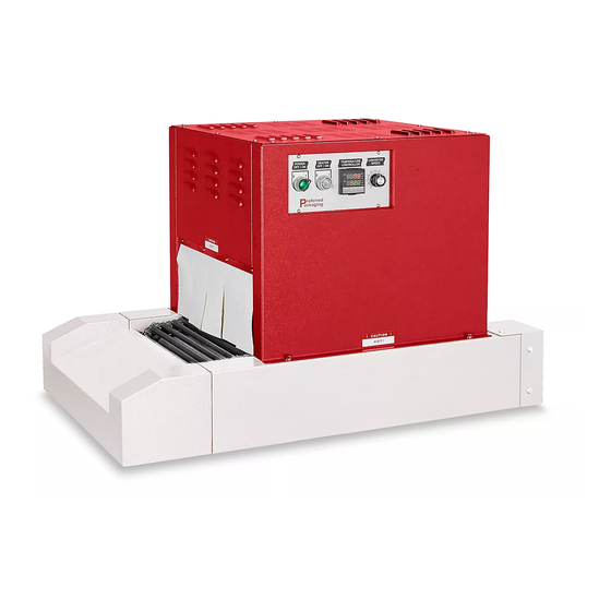
H-951
SHRINK TUNNEL
MACHINE SPECIFICATIONS
MODEL
Chamber Size
Volts
Amperage
Phase
Weight
PLACEMENT:
Determine where to place the shrink tunnel. Here are
some things to keep in mind:
• A power source with low voltage protection.
Machine will not operate properly if voltage is
too low.
• Avoid drafty areas. Heat may be drawn away from
machine and affect performance.
PAGE 1 OF 21
1-800-295-5510
uline.com
SYSTEM SPECIFICATIONS
PP 1606-20
Width: 16"
Height: 6"
Length: 20"
110
20
Single 1/0
250 lbs.
Para Español, vea páginas 8-14.
Pour le français, consulter les pages 15-21.
WARNING! Only authorized or trained
personnel should operate the Shrink Tunnel.
Do not tamper with electrical wiring. Always
switch off machine and disconnect power
before maintenance, cleaning or repairs.
Keep hands away from moving conveyors and
other moving parts.
DO NOT operate this machine without all
covers and guards in place. Severe injury may
result.
Heat-sealing arms and jaws become hot
after a period of use. Keep hands away while
machine is in operation.
Do not modify this machine in any way.
Modifying the Shrink Tunnel will void any
warranties.
Some plastic films used for sealing and
shrinking may release hazardous fumes
at high temperatures. Provide adequate
ventilation at all times.
Unplug the Shrink Tunnel when not in use.
IMPORTANT! Read this manual carefully
to familiarize yourself with the controls
and operation of this Shrink Tunnel before
installation or use. Keep this manual in a safe
place for future reference.
0519 IH-951
Advertisement
Table of Contents

Related Manuals for U-Line H-951


Summary of Contents for U-Line H-951
- Page 1 Para Español, vea páginas 8-14. Pour le français, consulter les pages 15-21. π H-951 1-800-295-5510 uline.com SHRINK TUNNEL SYSTEM SPECIFICATIONS MACHINE SPECIFICATIONS WARNING! Only authorized or trained personnel should operate the Shrink Tunnel. MODEL PP 1606-20 Do not tamper with electrical wiring. Always Chamber Size Width: 16"...
-
Page 2: Operator Controls
OPERATOR CONTROLS TEMPERATURE POWER HEATER CONVEYOR 100% Power Switch Heater Switch Temperature Control Conveyor Speed Control BASIC OPERATION 1. Turn Power Switch ON. This starts machine and cooling fan. 2. Turn Heater Switch ON. This starts the blower, conveyor motors and heater. 3. -
Page 3: Maintenance
MAINTENANCE TO CLEAN: To keep the Shrink Tunnel operating efficiently perform the following: 1. Run conveyor until the affected rollers are inside the • Monthly – Lubricate the conveyor chains with high heat chamber. temperature oil. Apply with a brush or spray with 2. - Page 4 INSTALLING LEG KIT USING FORKLIFT CONTINUED 5. Using 10 mm socket, 9. Secure leg to tunnel Figure 5 Figure 9 remove two metal with six bolts, three in straps that secured the each corner. tunnel to pallet. (See Figure 9) (See Figure 5) 10.
- Page 5 INSTALLING LEG KIT WITHOUT FORKLIFT 5. Rest the shrink tunnel on the planks, exposing the NOTE: You will need two 2 x 4" wood planks for this process. bottom of tunnel. (See Figure 14) Remove outer corrugated box from pallet. Figure 14 (See Figure 11) Figure 11...
- Page 6 INSTALLING LEG KIT WITHOUT FORKLIFT CONTINUED 9. Remove leg set and included hardware from box. 12. Repeat steps 10 and 11 with the other leg. (See Figure 18) 13. With two people, lift shrink tunnel upright. Figure 18 14. Finished unit with legs. (See Figure 21) Figure 21 10.
-
Page 7: Troubleshooting
TROUBLESHOOTING OPERATING ISSUE CAUSES RECOMMENDATIONS Conveyor not working Machine not powered correctly. Check power switch is ON and power cord is plugged into or wired to power. Check that main power is ON. Check fuse: Remove Top Panel (12 screws). Check fuse (F5 1 Amp fuse) Connected to wires 16 and 17. -
Page 8: Especificaciones Del Sistema
π H-951 800-295-5510 uline.mx TÚNEL TERMOENCOGIBLE ESPECIFICACIONES DEL SISTEMA ESPECIFICACIONES DE LA MÁQUINA ¡ADVERTENCIA! Solamente el personal autorizado o capacitado debe hacer funcionar el túnel termoencogible. MODELO PP 1606-20 Tamaño de la Ancho: 40.6 cm (16") No use las conexiones eléctricas de manera Cámara... -
Page 9: Controles Del Operador
CONTROLES DEL OPERADOR TEMPERATURE POWER HEATER CONVEYOR 100% Interruptor Interruptor Control de Control de la Velocidad de la de Encendido de Calefactor Temperatura Banda Transportada FUNCIONAMIENTO BÁSICO 1. Gire el interruptor de encendido a la posición ON (Encendido). Esto pone en marcha la máquina y el ventilador de enfriamiento. -
Page 10: Mantenimiento
CONTINUACIÓN DE CONTROL DE TEMPERATURA 3. Presione la tecla para mover el indicador 4. Una vez que se muestre la temperatura deseada, una posición a la izquierda. Mientras el número presione la tecla . Esto guarda la temperatura que ha introducido como Temperatura Establecida. parpadea, use las teclas para fijar el tercer número deseado. - Page 11 INSTALACIÓN DEL KIT DE PATAS UTILIZANDO MONTACARGAS 3. Coloque el 8. Mantenga una pata al fondo de la base del túnel. Diagrama 3 montacargas al frente Asegúrese de que el panel de la pata esté del túnel orientado hacia afuera y a lo largo del ancho del termoencogible con túnel.
- Page 12 INSTALACIÓN DEL KIT DE PATAS SIN USAR MONTACARGAS NOTA: Necesitará dos tablas de madera de 5. Ponga el túnel termoencogible encima de las 2 x 4" para este proceso. tablas con la base del túnel expuesta. (Vea Diagrama 14) Retire la caja de cartón externa de la tarima. (Vea Diagrama 11) Diagrama 14 Diagrama 11...
- Page 13 CONTINUACIÓN DE INSTALACIÓN DEL KIT DE PATAS SIN USAR MONTACARGAS 9. Retire el set de patas y la tornillería incluida de la 12. Repita los pasos 10 y 11 con la otra pata. caja. (Vea Diagrama 18) 13. Entre dos personas, levanten el túnel termoencogible hasta que quede erguido.
-
Page 14: Solución De Problemas
SOLUCIÓN DE PROBLEMAS PROBLEMA DE OPERACIÓN CAUSAS RECOMENDACIONES La banda transportadora no La máquina no recibe la Verifique que el interruptor de funciona alimentación eléctrica necesaria. encendido esté en posición ON y que el cable eléctrico esté enchufado a una fuente de alimentación. Verifique que la electricidad principal esté... -
Page 15: Spécifications Du Système
π H-951 1-800-295-5510 uline.ca TUNNEL DE RÉTRACTION SPÉCIFICATIONS DU SYSTÈME SPÉCIFICATIONS DE L'APPAREIL AVERTISSEMENT! Seul le personnel autorisé ou formé ARRÊT doit manipuler le tunnel de rétraction. MODÈLE PP 1606-20 N'altérez pas le câblage électrique. Éteignez et Dimensions de la chambre Largeur : 40,6 cm (16 po) -
Page 16: Commande De Température
COMMANDES OPÉRATEUR TEMPERATURE POWER HEATER CONVEYOR 100% Interrupteur Interrupteur Commande Commande de d'alimentation d'réchauffement de température vitesse du convoyeur OPÉRATION ÉLÉMENTAIRE Tournez l'interrupteur d'alimentation à ON (marche). Ceci démarre l'appareil et le ventilateur de refroidissement. 2. Tournez l'interrupteur de réchauffement à ON (marche). Ceci démarre la soufflante, les moteurs de convoyeur et le réchauffeur. Réglez la vitesse du convoyeur. -
Page 17: Entretien
ENTRETIEN NETTOYAGE : Pour maintenir l'état de fonctionnement efficace du tunnel de rétraction, effectuez l'entretien suivant : Faites fonctionner le convoyeur jusqu'à ce que les • Mensuellement : Lubrifiez les chaînes du convoyeur rouleaux touchés se situent à l'intérieur de la chambre de avec de l'huile haute température. - Page 18 INSTALLATION À L'AIDE D'UN CHARIOT-ÉLÉVATEUR SUITE 5. Retirez les deux Fixez le pied au tunnel Figure 9 Figure 5 languettes métalliques en utilisant six boulons, qui maintiennent le trois dans chaque coin. tunnel de rétraction (Voir Figure 9) à la palette à l'aide de la douille de 10 mm.
- Page 19 INSTALLATION SANS CHARIOT-ÉLÉVATEUR REMARQUE : Pour cette opération, vous aurez 5. Faites reposer le tunnel sur les planches, exposant ainsi le dessous du tunnel. (Voir Figure 14) besoin de deux planches en bois de 2 x 4 po. Retirez l'emballage de carton ondulé de la palette. Figure 14 (Voir Figure 11) Figure 11...
- Page 20 INSTALLATION SANS CHARIOT-ÉLÉVATEUR SUITE Retirez les pieds et le matériel d'installation de la 12. Répétez les étapes 10 et 11 avec l'autre pied. boîte. (Voir Figure 18) 13. Redressez le tunnel à l'aide d'une autre personne. Figure 18 14. Produit fini muni de pieds. (Voir Figure 21) Figure 21 10.
-
Page 21: Dépannage
DÉPANNAGE PROBLÈME DE FONCTIONNEMENT CAUSES RECOMMANDATIONS Le convoyeur ne fonctionne pas Appareil incorrectement Confirmez si l'interrupteur d'alimentation alimenté. est à la position ON et que le cordon d'alimentation est branché sur ou câblé à une source d'alimentation. Confirmez que la source d'alimentation principale est enclenchée.