Advertisement
WIRELESS TRANSMISSION ADAPTOR
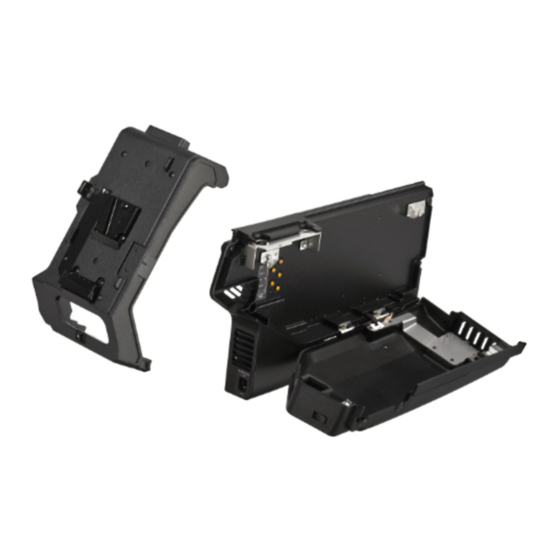
HKC-WL50
利用条件:
① 本情報はソニー製品の販売、設置、設定、使用の目的でのみご利用ください。かかる目的以外での利用を禁止します。
② 著作者の事前の書面による許可なく、本情報の全部または一部の複写、複製、転載、改変、翻訳、送信等を禁止します。
情報改訂:
本情報は、当社の裁量により、予告なく変更されることがあります。ご使用される場合、本情報が最新の情報であることを確認のうえ、
ご使用ください。
Conditions of Use:
(1) Please use this information only for the purpose of sales, installation, configuration, and use of Sony products. Using this information
for any purpose other than the purpose described foregoing is forbidden.
(2) Do not copy, replicate, reproduce, alter, translate, transmit, sell, lease, or distribute this information in whole or in part without the prior
written permission of the author.
Revision of Information:
This information may be changed or updated at any time without any prior notice. Please confirm that this information is up-to-date before
using it.
INSTALLATION MANUAL
1st Edition
Advertisement
Table of Contents

Related Manuals for Sony HKC-WL50


Summary of Contents for Sony HKC-WL50
- Page 1 ご使用ください。 Conditions of Use: (1) Please use this information only for the purpose of sales, installation, configuration, and use of Sony products. Using this information for any purpose other than the purpose described foregoing is forbidden. (2) Do not copy, replicate, reproduce, alter, translate, transmit, sell, lease, or distribute this information in whole or in part without the prior written permission of the author.
- Page 2 警告 このマニュアルは,サービス専用です。 お客様が,このマニュアルに記載された設置や保守,点検,修理などを行うと感電や火災, 人身事故につながることがあります。 危険をさけるため,サービストレーニングを受けた技術者のみご使用ください。 WARNING This manual is intended for qualified service personnel only. To reduce the risk of electric shock, fire or injury, do not perform any servicing other than that contained in the operating instructions unless you are qualified to do so. Refer all servicing to qualified service personnel.
-
Page 3: Table Of Contents
1-2. Overview of Installation ............................... 3 1-2-1. Installing HKC-CN50 to the Camera Body ........................3 1-2-2. Installing HKC-WL50 (Outside Panel Assembly) to the Camera Body ................3 1-2-3. Installing HKC-WL50 (Battery Adaptor Assembly) to the Camera Body ................. 4 1-3. Installation Procedures ................................. 5 1-3-1. -
Page 4: Section 1 Installation
Section 1 Installation Purpose of this manual This manual is an installation manual of HKC-WL50. Intended for use by system and service engineers, this manual describes information on installation of HKC-WL50. Related manual Besides this installation manual, the following manual is available for HKC-WL50. -
Page 5: Overview Of Installation
Outside panel 1-2-2. Installing HKC-WL50 (Outside Panel Assembly) to the Camera Body Note For details on the installation procedure, refer to “1-3-1. Installing HKC-WL50 (Outside Panel Assembly) to the Camera Body”. Camera body Outline of installation procedure (1) Install the wireless unit to the HKC-WL50 (outside panel assembly). -
Page 6: Installing Hkc-Wl50 (Battery Adaptor Assembly) To The Camera Body
1-2-3. Installing HKC-WL50 (Battery Adaptor Assembly) to the Camera Body Note For details on the installation procedure, refer to “1-3-2. Installing HKC-WL50 (Battery Adaptor Assembly) to the Camera Body”. Outline of installation procedure (1) Install the hinge plate and the lock bracket to the camera body. -
Page 7: Installation Procedures
1-3. Installation Procedures 1-3-1. Installing HKC-WL50 (Outside Panel Assembly) to the Camera Body Push the two buttons and open the cover of HKC-WL50 (outside panel assembly). HKC-WL50 (outside panel assembly) Button Cover Button Secure the wireless unit using the mounting holes shown in the figure. - Page 8 PSW3 x 6 Antenna bracket Install the transmission antenna and the receiving antenna to the antenna bracket. Note To install the transmission antenna, use the nut supplied with HKC-WL50. Attach the antenna cushion. Note • Align the antenna cushion with the reference line shown in the figure below.
- Page 9 Attach the antenna bracket with the three screws. Note • When attaching the antenna bracket, match the two bosses with the two holes. PSW3 x 6 Antenna bracket Holes Bosses Attach the antenna cushion to the outside panel. Antenna cushion Outside panel Close the cover.
- Page 10 Note To prevent damage in the unit, turn off the power and disconnect the power cord or remove the battery before starting the following work. Open the DC OUT lid (860) in the direction of the arrow A. 10. Loosen the five screws with stopper to open the outside panel assembly in the direction of arrow B. Outside panel assembly B3 x 10 (Screws with stopper)
- Page 11 14. Remove the outside panel support from the hook of the main frame and remove the outside panel assembly. Outside panel support Outside panel assembly Hook of main frame 15. Open the inside SW cover and turn the three switch levers in the direction of arrow. 16.
- Page 12 17. Remove the screw, and then remove the SW-1742 board. SW-1742 board 18. Remove the two screws, and then remove the DC IN connector. 19. Turn the DC IN connector 180 degrees in the direction of the arrow. M2.6 x 5 M2.6 x 5 DC IN connector 20.
- Page 13 21. Disconnect the harness (DC-OUT) from the connector (CN5003) on the PS-943 board. 22. Release the harness (DC-OUT) from the clamper. Clamper Harness CN5003 (DC-OUT) (PS-943 board) 23. Remove the two screws, and then remove the harness (DC-OUT) assembly. 24. Release the harness (DC-OUT) from the two clampers. Harness (DC-OUT) assembly Clampers PSW2 x 5...
- Page 14 25. Pull out the harness (DC-OUT) from the main body. Harness (DC-OUT) assembly 26. Remove the two screws, and then remove the DC OUT cover and the harness (DC-OUT) from the DC OUT holder. DC-OUT holder Harness (DC-OUT) DC-OUT cover PSW2 x 5 27.
- Page 15 28. Pass the harness (DC-OUT-POWER) to the main body. Harness (DC-OUT POWER) assembly Connector terminal (brown) Connector terminal (white) 29. Connect the harness (DC-OUT POWER) to the connector (CN5003) on the PS-943 board. 30. Fix the harness (DC-OUT-POWER) with the clamper. Clamper Harness CN5003...
- Page 16 31. Pull out the redundant part of the harness to the outside. Note Pull out the entire redundant part of the harness to the outside. Harness (DC-OUT-POWER) assembly Redundant part of the harness 32. Fix the harness (DC-OUT-POWER) with the two clampers as shown below. Note •...
- Page 17 34. Attach the SW-1742 board, and then tighten the screw. PSW3 x 6 SW-1742 board...
- Page 18 35. Turn the three switch levers in the direction of arrow. 36. Open the inside SW cover and attach the inside panel assembly. Note To prevent the harness from being pinched, make sure that the harness does not overlap the positions of the holes of the screws, the build-up harness guard, and the harness itself shown in the figure.
- Page 19 39. Fix the harness (DC-OUT-POWER) with the clamper. Clamper Harness (DC-OUT-POWER) CN1007 (IF-1331 board) HKC-WL50 (Outside panel assembly) 40. Close the HKC-WL50 (outside panel assembly). 41. Tighten the screw with stopper. B3 x 10 (Screws with stopper) HKC-WL50 (outside panel assembly)
- Page 20 42. Push the two buttons and open the cover of the HKC-WL50 (outside panel assembly). Button Button Cover HKC-WL50 (outside panel assembly) 43. Tighten the four screws with stopper. 44. Close the cover. B3 x 10 (Screws with stopper) Cover...
-
Page 21: Installing Hkc-Wl50 (Battery Adaptor Assembly) To The Camera Body
1-3-2. Installing HKC-WL50 (Battery Adaptor Assembly) to the Camera Body Remove the two cover sheets. Cover sheet Cover sheet Install the hinge plate with the two screws. M3 x 8 M3 x 8 Hinge plate Remove the two screws. Note Do not reuse the removed two screws. - Page 22 Pull the lock bracket in the direction of the arrow and tighten the screws. M3 x 8 Lock bracket M3 x 8 Remove the DC IN connector cap in the direction of the arrow and connect the cord of the HKC-WL50 (battery adaptor assembly) to the DC IN connector. DC IN connector HKC-WL50...
- Page 23 Loosen the two screws. 10. Push the HKC-WL50 (battery adaptor assembly) in the direction of the arrow and tighten the two screws. 11. Lift the battery adaptor while sliding the knob in the direction of arrow A to remove the battery adaptor.
- Page 24 13. Attach the rating label to the camera body. Rating label...
-
Page 25: Arranging Harness When Removing The Hkc-Wl50 (Outside Panel Assembly)
1-4. Arranging Harness when Removing the HKC-WL50 (Outside Panel Assembly) When replacing the HKC-WL50 (outside panel assembly) with another one, arrange the harness (DC-OUT-POWER) as described below. Pass the harness (DC-OUT-POWER) through the clamper again. Place the harness (DC-OUT-POWER) at the back of the DPR-390 board. -
Page 26: Revision History
Revision History Date History Contents ― 2019. 3 1st Edition 9-932-686-01... - Page 27 (操作,保守等) と異なる目的で本マニュアルを 使用する ことを禁止します。 The material contained in this manual consists of information that is the property of Sony Corporation. Sony Corporation expressly prohibits the duplication of any portion of this manual or the use thereof for any purpose other than the operation or maintenance of the equipment described in this manual without the express written permission of Sony Corporation.
- Page 28 Printed in Japan HKC-WL50 (SY) J,E 2019. 3 08 Sony Corporation 9-932-686-01 © 2019...