Ricoh JP5000 Service Manual
Hide thumbs
Also See for JP5000:
- Operating instructions manual (465 pages) ,
- Operating instructions manual (232 pages) ,
- Operating instructions manual (232 pages)
Table of Contents
Advertisement
Quick Links
Advertisement
Table of Contents

Related Manuals for Ricoh JP5000


Summary of Contents for Ricoh JP5000
- Page 1 SERVICE MANUAL (Machine code: C229)
-
Page 2: Important Safety Notices
IMPORTANT SAFETY NOTICES PREVENTION OF PHYSICAL INJURY 1. Before disassembling or assembling parts of the printer and peripherals, make sure that the power cord is unplugged. 2. The wall outlet should be near the printer and easily accessible. 3. If any adjustment or operation check has to be made with exterior covers off or open while the main switch is turned on, keep hands away from electrified or mechanically driven components. -
Page 3: Safety And Ecological Notes For Disposal
SAFETY AND ECOLOGICAL NOTES FOR DISPOSAL 1. Dispose of replaced parts in accordance with local regulations. 2. Used ink and masters should be disposed of in an environmentally safe manner and in accordance with local regulations. 3. When keeping used lithium batteries (from the main processing units) in order to dispose of them later, do not store more than 100 batteries (from the main processing units) per sealed box. - Page 4 IMPORTANT SAFETY NOTICES PREVENTION OF PHYSICAL INJURY 1. Before disassembling or assembling parts of the printer and peripherals, make sure that the power cord is unplugged. 2. The wall outlet should be near the printer and easily accessible. 3. If any adjustment or operation check has to be made with exterior covers off or open while the main switch is turned on, keep hands away from electrified or mechanically driven components.
- Page 5 SAFETY AND ECOLOGICAL NOTES FOR DISPOSAL 1. Dispose of replaced parts in accordance with local regulations. 2. Used ink and masters should be disposed of in an environmentally safe manner and in accordance with local regulations. 3. When keeping used lithium batteries (from the main processing units) in order to dispose of them later, do not store more than 100 batteries (from the main processing units) per sealed box.
-
Page 6: Overall Information
1 July, 1998 SPECIFICATIONS 1. OVERALL INFORMATION 1.1 SPECIFICATIONS Configuration: Desktop Master Processing: Digital with 400 dpi thermal head Scanning (Pixel Density): 400 dpi CCD Printing Process: Fully automatic stencil system, with one drum and pressure cylinder system Original Type: Sheet/Book In Platen Mode: Document size:... - Page 7 SPECIFICATIONS 1 July, 1998 Printing Area: Metric size version models: (At 20 °C/ 65 % RH) 290 mm x 409 mm Inch size version models: 290 mm x 419 mm [11.4" x 16.4"] With optional A4 drum: 290 mm x 204 mm [11.4" x 8.0"] Edge Margins: Leading edge: 10 mm (At the "0"...
- Page 8 1 July, 1998 SPECIFICATIONS Noise Emission: At 60 rpm printing speed: 57 dB (At operation position) At 90 rpm printing speed: 60 dB At 120 rpm printing speed: 64 dB Weight: 94 kg [207 lb] 101 kg [222.7 lb] with ADF Dimensions: Trays closed: 625 mm x 650 mm x 574 mm...
- Page 9 SPECIFICATIONS 1 July, 1998 • A3 Drum Available Options • A4 Drum • Document Feeder • Key Counter • Memory Board (Editing Function) • PC Controller • Interface Board (Standard for the U.S.A and European versions)
-
Page 10: Guide To Components And Their Function
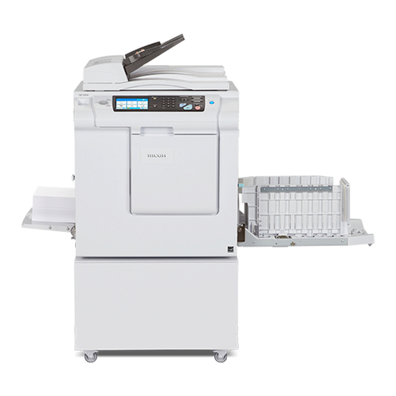
1 July, 1998 GUIDE TO COMPONENTS AND THEIR FUNCTION 1.2 GUIDE TO COMPONENTS AND THEIR FUNCTION 1.2.1 MACHINE EXTERIOR C229V500.WMF 1. Front Door Open for access to the inside of the machine. 2. Flip-up Cover Open to access the Image Density key and so on. -
Page 11: Machine Interior
MACHINE INTERIOR 1 July, 1998 1.3 MACHINE INTERIOR C229V501.WMF... - Page 12 1 July, 1998 MACHINE INTERIOR 1. Main Switch Use to turn the power on or off. 2. Paper Alignment Wing Use to lift or lower the paper alignment Knobs wings. 3. Paper Alignment Wings Lift or lower the wings depending on the paper type you use.
-
Page 13: Operation Panel
MACHINE INTERIOR 1 July, 1998 1.3.1 OPERATION PANEL C229V502.WMF 1. Quality Start key 11. Economy Mode key 2. Security key 12. On Line key 3. Skip Feed key 13. Job Separator key 4. User Tools key 14. Combine key Press to change the default Press to combine originals onto settings and conditions to meet one print. - Page 14 1 July, 1998 MACHINE INTERIOR C229V502.WMF 18. Program key 23. Start key Press to make a master. Press to input or recall user programs. 24. Auto Cycle key Use to process the master and 19. Number keys make prints at one stroke. 20.
- Page 15 MACHINE INTERIOR 1 July, 1998 1.3.2 INDICATORS C229V503.WMF 1. Special Feature indicator 5. Color Drum indicator This indicator is lit when you This indicator is lit when the color press keys under the flip-up drum unit is installed. cover. 2. Monitors 6.
-
Page 16: Printing Process Overview
1 July, 1998 PRINTING PROCESS OVERVIEW 1.4 PRINTING PROCESS OVERVIEW C229V008.WMF 1. Master Ejecting: Ejects the used master wrapped around the drum into the master eject box. 2. Scanning: Scans the original image with the CCD through the mirrors and the lens. 3. -
Page 17: Mechanical Component Layout
MECHANICAL COMPONENT LAYOUT 1 July, 1998 1.5 MECHANICAL COMPONENT LAYOUT C229V008.WMF 1. Master Feed Control Roller 18. Idling Roller 2. Lens 19. Transport Belts 3. CCD 20. Job Separator Unit 4. SBU 21. Paper Delivery Table 5. Tension Roller 22. Master Eject Rollers 6. -
Page 18: Electrical Component Layout
1 July, 1998 ELECTRICAL COMPONENT LAYOUT 1.6 ELECTRICAL COMPONENT LAYOUT 1.6.1 PRINTED CIRCUIT BOARD LAYOUT C229V007.WMF 1-13... - Page 19 ELECTRICAL COMPONENT LAYOUT 1 July, 1998 1.6.2 SCANNER SECTION C229V001.WMF 1.6.3 PAPER FEED SECTION C229V002.WMF 1-14...
- Page 20 1 July, 1998 ELECTRICAL COMPONENT LAYOUT 1.6.4 MASTER EJECT, PRESSURE CYLINDER, AND OTHER SECTIONS C229V003.WMF 1-15...
-
Page 21: Master Making Unit
ELECTRICAL COMPONENT LAYOUT 1 July, 1998 1.6.5 PAPER DELIVERY SECTION C229V010.WMF 1.6.6 MASTER MAKING UNIT C229V005.WMF 1-16... - Page 22 1 July, 1998 ELECTRICAL COMPONENT LAYOUT 1.6.7 DRUM UNIT C229V006.WMF 1-17...
- Page 23 Enables the image editing function and data printout via SP mode. This is an option. Interface Board Enables the connection with the PC controller. This is an option for the China and Ricoh Asia versions. Thermal Head Power Provides dc power to the thermal head.
- Page 24 1 July, 1998 ELECTRICAL COMPONENT LAYOUT Motors Index No. Name Function Scanner Drive Motor Drives the scanner. Feed Pressure Motor Drives the paper feed pressure adjustment mechanism. Registration Motor Feeds the paper to align it with the image on the master on the drum.
- Page 25 ELECTRICAL COMPONENT LAYOUT 1 July, 1998 Sensors Index No. Name Function Original Width Sensor Detects the width of the original on the exposure glass. Scanner HP Sensor Detects when the scanner is at home position. Platen Cover Sensor Detects if the platen cover is open or closed. Original Length Sensor Detects the length of the original on the exposure glass.
- Page 26 1 July, 1998 ELECTRICAL COMPONENT LAYOUT Index No. Name Function Paper Exit Sensor Detects paper misfeeds at the exit. A3 Cam Sensor Detects when the A3 printing pressure cam is used. A4 Cam Sensor Detects when the A4 printing pressure cam is used.
-
Page 27: Drive Layout
DRIVE LAYOUT 1 July, 1998 1.7 DRIVE LAYOUT 1.7.1 OVERVIEW C229V504.WMF 1. Clamper Opening Arm Sector 9. Pressure Cylinder Drive Gear Gear (for the master eject position) (Including the Scissors Gear) 2. Master Pick-up Roller Sector Gear 10. Registration Roller Lifting Cam Drive Gear 3. -
Page 28: Main Drive
1 July, 1998 DRIVE LAYOUT 1.7.2 MAIN DRIVE C229V505.WMF 18. Drum 24. Idler Gear/Pulley 19. Pressure Cylinder 25. Pressure Cylinder Drive Gear (including the Scissors Gear) 20. Printing Pressure Cam 26. Primary Gear/Pulley 21. Exit Pawl Drive Cam Gear 27. Drum Drive Gear/Pulley 22. -
Page 29: Detailed Section Descriptions
1 July, 1998 SCANNER AND OPTICS 2. DETAILED SECTION DESCRIPTIONS 2.1 SCANNER AND OPTICS 2.1.1 OVERVIEW C229D094.WMF The exposure lamp, a xenon lamp [A], illuminates the original. The 1st, 2nd, and 3rd mirrors, and a lens [B] reflect the image onto a CCD (Charge Coupled Device) [C]. -
Page 30: Scanner Drive
SCANNER AND OPTICS 1 July, 1998 2.1.2 SCANNER DRIVE Rear Front C229D095.WMF A stepper motor drives the scanner. The scanner drive motor [A] drives the 1st and 2nd scanners [B, C] through the timing belt [D], scanner drive pulley [E], scanner drive shaft [F], and two scanner wires [G]. -
Page 31: Original Size Detection In Platen Mode
1 July, 1998 SCANNER AND OPTICS 2.1.3 ORIGINAL SIZE DETECTION IN PLATEN MODE C229D120.WMF C229D096.WMF C229D116.WMF In Platen mode, the size of paper on the paper table usually determines the image reading area for the original. If Reduction or Enlargement mode is used, the magnification ratio affects the image reading area. - Page 32 SCANNER AND OPTICS 1 July, 1998 The platen cover sensor [C] or the DF position sensor [D] informs the main CPU of the original size when the platen is about 15 cm above the exposure glass. At this time, only the sensors located underneath the original receive the reflected light and switch on.
-
Page 33: Image Processing
1 July, 1998 IMAGE-PROCESSING 2.2 IMAGE-PROCESSING 2.2.1 OVERVIEW Memory Thermal Board Head (Option) M P U C229D501.WMF The CCD converts the light reflected from the original into an analog signal. The CCD line has 5,000 pixels and the resolution is 400 dpi (15.7 lines/mm). After the above process, the A/D converter built into the SBU transforms the analog signals into 8-bit signals. -
Page 34: Auto Background Correction
IMAGE-PROCESSING 1 July, 1998 2.2.2 AUTO BACKGROUND CORRECTION C229D097.WMF Auto background correction mode can be used in Photo/Letter, Photo, and Tint modes. The default setting does not allow the user to select auto background correction mode. (Use SP 2-31 to enable this mode.) Auto background correction prevents the background of an original from appearing on copies. -
Page 35: Auto Shading
1 July, 1998 IMAGE-PROCESSING 2.2.3 AUTO SHADING C229D504.WMF There are two auto shading methods: black level and white level correction. Auto shading corrects errors in the signal level for each pixel. - Black Level Correction - The CPU reads the black dummy data from one end of the CCD signal (64 pixels are blackened at the end) and takes an average of the black dummy data. -
Page 36: Filtering And Main Scan Magnification/Reduction
IMAGE-PROCESSING 1 July, 1998 2.2.4 FILTERING AND MAIN SCAN MAGNIFICATION/REDUCTION Overview Filtering and main scan magnification process the image data after auto shading. However, to reduce moire in the image, the processing order depends on the reproduction ratio, as follows: 1) Reduction and Full size Main Scan Reduction →... - Page 37 1 July, 1998 IMAGE-PROCESSING Main Scan Magnification/Reduction C229D506.WMF The IPU chip handles reduction and enlargement in the main scan direction. NOTE: Changing the scanner speed accomplishes reduction and enlargement in the sub-scan direction. When making a copy using the ADF, the magnification circuit creates a mirror image.
-
Page 38: Binary Processing
IMAGE-PROCESSING 1 July, 1998 2.2.5 BINARY PROCESSING In the IPU chip, the 8-bit data is converted into 1-bit data for black or white pixels. The binary processing for the letter mode is different from that for the photo mode and the letter/photo mode as follows: 1) Letter mode: Binary processing 2) Letter/Photo mode:... -
Page 39: Optional Memory Board
1 July, 1998 IMAGE-PROCESSING 2.2.6 OPTIONAL MEMORY BOARD The optional memory board, or editing function board, has 4-Mbyte RAM, which corresponds to the amount of memory required for an A3 original. This enables the following image editing functions. - Memory Combine Mode - Combined images of 4, 8, or 16 originals are printed on the same sheet of paper. -
Page 40: Thermal Head
IMAGE-PROCESSING 1 July, 1998 2.2.7 THERMAL HEAD Specifications • Length 292.6 mm • Number of thermal head elements 4608 • Density of thermal head elements 400 dpi Thermal Head Control The thermal head contains heating elements at a density of 400 dpi. The thermal heating elements melt the over-coating and polyester film layers of the master, in accordance with the image signal for each pixel. - Page 41 1 July, 1998 IMAGE-PROCESSING Remarks for Handling the Thermal Head Pay careful attention to the following remarks when servicing: • Do not touch the surface • Remove any foreign materials from with bare hands. If this the platen roller. occurs, clean the surface •...
-
Page 42: Master Eject
MASTER EJECT 1 July, 1998 2.3 MASTER EJECT 2.3.1 OVERVIEW C229D106.WMF The master remains wrapped around the drum to prevent the ink from drying. Therefore, making a new master begins from the master ejecting process. When the Start key is pressed to scan the original, the drum rotates from the home position to the master eject position. -
Page 43: Master Eject Mechanism
1 July, 1998 MASTER EJECT 2.3.2 MASTER EJECT MECHANISM Overview Rear Front C229D112.WMF Two photosensors (the 1st and 2nd drum position sensors) and the feeler on the rear drum flange determine the drum position. The drum is at the home position when the feeler actuates the 1st drum position sensor. - Page 44 MASTER EJECT 1 July, 1998 Drum Lock Mechanism The clamper motor drives the drum guide [C]. The Rear clamper closed position sensor [A] and clamper open position sensor [B] monitor the position of the drum guide. When the drum reaches the master eject position, the drum guide moves until the clamper open position...
- Page 45 1 July, 1998 MASTER EJECT Master Pick-up Roller Drive and Master Clamper Open Rear Front C229D081.WMF When the clamper motor opens the drum master clamper [B], the master pick-up roller [A] contacts the leading edge of the master on the drum. The clamper motor moves the master pick-up roller against the drum through the idle gear [D], while driving the clamper opening arm [C].
- Page 46 MASTER EJECT 1 July, 1998 Master Eject and Transportation Rear Front C229D082.WMF The master pick-up roller [A] and the upper and lower master eject rollers [B] all turn together. They start turning as soon as the drum reaches the master eject position.
- Page 47 1 July, 1998 MASTER EJECT Master Eject Roller Unit Drive The master eject motor [A] turns the master pick-up roller [B] with the upper and lower master eject rollers [C]. When the unit is slid out (explained below), the joint [D] disengages.
- Page 48 MASTER EJECT 1 July, 1998 Master Eject Box Mechanism C229D092.WMF C229D085.WMF The user can slide the master eject box out from the operation side of the machine. The front handle of the box [A] has a lock mechanism as shown above. The master eject box contains a pressure plate [B], which compresses the ejected masters in the box.
- Page 49 1 July, 1998 MASTER EJECT The ejected masters in the box can be taken out by sliding the eject lever [A]. The inner bottom case [C] moves towards the rear of the box. Masters are ejected from an open door at the rear of the box.
-
Page 50: Pressure Plate Drive Mechanism
MASTER EJECT 1 July, 1998 2.3.3 PRESSURE PLATE DRIVE MECHANISM Overview There are three phases. • Homing At power on or when recovering from an error or jam, the machine makes sure that the pressure plate is at home position. This is because, if certain errors occur, the pressure plate may not be in the home position at the start of a job •... - Page 51 1 July, 1998 MASTER EJECT Homing Operation At power on or when recovering from an error or jam condition, the machine carries out the pressure plate homing operation. If certain errors occur, the pressure plate may not be in the home position.
- Page 52 MASTER EJECT 1 July, 1998 Shift to the Master Eject Position When the Start key is pressed to make a new master, the drum turns to the master eject position. During this period, the pressure plate travels to the master eject ready position.
- Page 53 1 July, 1998 MASTER EJECT When there are a lot of masters If there are a lot of used masters in the box, the pressure plate cannot move to the lower limit position. If the lower limit position sensor [B] is not actuated within 7 seconds after the pressure plate starts traveling from the master eject ready...
- Page 54 MASTER EJECT 1 July, 1998 Pressure Plate Operation Timing Chart Does not reach here after 6 seconds ⇒ Motor locked HP Sensor Limit Position Sensor Master Box Direction Drum Drum Direction Pressure Plate Motor Eject Compressing Position HP Returned Position (Stays for 2 seconds) Check when rotating in the Number of HP Sensor On or Off Edges...
-
Page 55: Master Feed
1 July, 1998 MASTER FEED 2.4 MASTER FEED 2.4.1 OVERVIEW C229D115.WMF A: Master Edge Sensor G: Master Roll B: Tension Roller H: Master End Sensor C: Platen Roller I: Master Vacuum Fans D: Thermal Head J: Master Buffer Duct E: Master Set Roller K: Cutter F: Master Set Sensor L: Master Feed Control Roller... -
Page 56: Master Set Mechanism
MASTER FEED 1 July, 1998 2.4.2 MASTER SET MECHANISM Master Roll Set The master set sensor [A] checks to see if the master roll was installed properly. After inserting the master making unit, the sensor detects the leading edge of the master. The master is fed in until the leading edge reaches the master feed control roller. - Page 57 1 July, 1998 MASTER FEED Master Buffer Duct Entrance Control While the master is being transported to the master Rear feed control roller [A], the duct entrance solenoid [C] closes the master buffer duct entrance plate [B]. This prevents the duct entrance from catching the leading edge of the master.
-
Page 58: Master Making And Feed Mechanism
MASTER FEED 1 July, 1998 2.4.3 MASTER MAKING AND FEED MECHANISM Master Feed Mechanism Rear View C229D003.WMF The master feed motor [F], a stepper motor, drives the master feed control [A], tension [B], platen [C] and master set [D] rollers. The tension roller feeds the master slightly faster than the platen roller, to prevent the master from creasing. - Page 59 1 July, 1998 MASTER FEED Platen Roller Pressure Release Rear View C229D002.WMF The platen release motor [A] gives half a turn to the platen release cam [B] to apply or release the platen roller [C] pressure. As the motor turns, the actuator on the gear interrupts the platen release sensor [D].
- Page 60 MASTER FEED 1 July, 1998 Master Buffer Mechanism Rear Front C229D000.WMF To minimize master processing time, the master is stored in the master buffer duct [A] after the thermal head transfers the image to it. The stored master is fed out from the duct when the drum reaches the master making position after master ejecting.
- Page 61 1 July, 1998 MASTER FEED 2.4.4 WRAPPING THE MASTER AROUND DRUM Rear Front C229D091.WMF Drum Lock and Master Clamper Open As explained in the Master Eject section, the drum guide [A] holds the drum at the master eject and master making positions. When the drum reaches the master making position, the drum guide moves to engage the stud [B] on the rear drum flange until the clamper open position sensor [C] is actuated.
- Page 62 MASTER FEED 1 July, 1998 Master Feed Control Roller Mechanism Rear Front C229D090.WMF The master feed clutch [A] connects and disconnects the drive from the master feed motor to the master feed control roller [B]. The master feed control roller only turns in the following cases: •...
- Page 63 1 July, 1998 MASTER FEED Master Clamping and Wrapping around the Drum Rear Front C229D006.WMF The master feed clutch turns on to feed out the master from the master buffer duct. The master is fed out 31 mm and reaches the drum master clamper [A]. The master feed clutch turns off temporarily.
- Page 64 MASTER FEED 1 July, 1998 Master Cut and Buffer Duct Entrance Control When the thermal head has finished making the master and the master has been fed out of the duct, the cutter [A] will cut the master. In preparation for making the next master, the leading edge of the next master is continuously fed to the...
- Page 65 1 July, 1998 MASTER FEED Cutter Mechanism C231D573.WMF Rear View The cutter motor [D] drives the screw shaft [A], moving the cutter holder [C] forward and backward. There are two cutter blades [B] in the holder. While the cutter holder [C] travels to the front (the operation side of the machine), the blades cut the master.
- Page 66 MASTER FEED 1 July, 1998 2.4.5 MASTER MAKING UNIT SLIDE-OUT MECHANISM The master making unit can be slid out along the guide rails. There are three connectors, which enable electrical contact for the installed unit. The master making unit set sensor [A] (a push switch) detects when the unit is out.
- Page 67 1 July, 1998 DRUM 2.5 DRUM 2.5.1 OVERVIEW C229D109.WMF The drum surface is composed of a stainless-steel screen (metal screen [A]) and two layers of polyester screens (cloth screen [B]). In addition, a drum master clamper [C] clamps the leading edge of the master wrapped around the drum. Inside the drum are the ink roller [D] and doctor roller [E], which create a precisely maintained gap, known as the doctor gap, to supply a thin layer of ink on the screens and master [F].
-
Page 68: Ink Supply And Kneading Mechanism
DRUM 1 July, 1998 2.5.2 INK SUPPLY AND KNEADING MECHANISM C229D010.WMF Ink Cartridge Installation The ink cartridge [A] is in the drum. The ink cartridge set sensor [B] (a push switch) detects the presence of the ink cartridge. Ink Supply Mechanism The whole ink supply mechanism is inside the drum. - Page 69 1 July, 1998 DRUM Ink Detection Board C229D110.WMF C229D011.WMF Ink Detection Mechanism The ink detecting pins [A] function as a capacitor electrode and detect the capacitance between the ink [B] and doctor [C] rollers. The capacitance level changes with the ink level. When the ink level is high the pins touch ink, and the capacitance increases.
- Page 70 DRUM 1 July, 1998 Drum Type Detection There are also dip switches on the ink detection board. The settings depend on the drum type in the following manner: DPS901 Standard Drum Optional Color Drum Optional A4 Drum Not Used Note: If the CPU detects that all dip switches are off, it assumes that there is no drum in the machine.
- Page 71 1 July, 1998 DRUM Ink Kneading Mechanism Rear Front C229D007.WMF C229D012.WMF A gear [C] on the drum shaft drives the ink [A] and doctor [B] rollers. The doctor roller spreads the ink evenly on the ink roller. The ink roller drive gear [D] has a one-way clutch to prevent the ink roller from being manually turned in the reverse direction.
- Page 72 DRUM 1 July, 1998 Drum Idling Mechanism Rear Front C229D013.WMF Quality Start Mode In Quality Start mode; the machine enters the drum idling mode before printing. This ensures that the first print has sufficient ink density even if the machine was not used for a long time.
- Page 73 1 July, 1998 DRUM Auto Quality Start Mode Auto Quality Start is done if the user does not select Quality Start mode. (It can be disabled with a user tool.) In Auto Quality Start mode, the idling motion depends on how long the machine was not in use and on the temperature detected by the thermistor [A] in the drum.
- Page 74 DRUM 1 July, 1998 Drum Rotation Speed during Idling Whether the machine is in Quality Start mode or not, the drum idling roller is always used for the trial print (the print to complete the master making), and for the first and second prints.
-
Page 75: Drum Shift Mechanism For Image Side-To-Side Shift
1 July, 1998 DRUM 2.5.3 DRUM SHIFT MECHANISM FOR IMAGE SIDE-TO-SIDE SHIFT Rear Front C229D014.WMF The image side-to-side shift function shifts the outer drum sleeve (with master) from front to back. The shifting mechanism is inside the drum. It consists of the drum shift motor [A] and a rack and pinion mechanism. -
Page 76: Drum Set Mechanism
DRUM 1 July, 1998 2.5.4 DRUM SET MECHANISM Upper Handle and Lock There are two grips [A, and B] to hold the drum. When the upper grip [A] is pulled up, it releases the drum locking mechanism. C229D015.WMF Front Lock Lever When the drum is set correctly and the front lever [C] is raised, the drum is locked into position. -
Page 77: Drum Drive Mechanism
1 July, 1998 DRUM 2.5.5 DRUM DRIVE MECHANISM Rear View C229D018.WMF C229D020.WMF The main motor [A] drives the drum via the timing belt. When the drum is set in the machine, the stud [B] on the joint disk engages the drum drive gear [C]. This transmits the main motor drive to the drum unit. -
Page 78: Master Detection
DRUM 1 July, 1998 2.5.6 MASTER DETECTION The 1st drum master sensor [A] detects a master on the drum. If a master is on the drum, the black patch [B] is covered and the sensor detects the light reflected from the master. Printing starts when the start key is pressed. -
Page 79: Paper Feed
1 July, 1998 PAPER FEED 2.6 PAPER FEED 2.6.1 OVERVIEW Rear Front C229D053.WMF Pick-up and Feed The top sheet of paper on the paper table is first fed by the pick-up roller [D]. Then, it is separated by the paper feed roller [F] and the friction pad [E], and fed to the registration rollers [A]. -
Page 80: Paper Feed Mechanism
PAPER FEED 1 July, 1998 2.6.2 PAPER FEED MECHANISM Rear Front C229D054.WMF C229D056.WMF The pick-up roller [C] and paper feed roller [A] are driven by the paper feed motor [B] as shown. The top sheet of the paper is separated from the paper stack by the friction between the roller and the friction pad [D], and fed to the registration roller. - Page 81 1 July, 1998 PAPER FEED Rear View C229D118.WMF Since paper feed timing must be synchronized with pressure cylinder rotation (so that the paper clamper on the pressure cylinder can catch paper’s leading edge accurately), the paper feed motor on timing is maintained by the feed start sensor [C].
-
Page 82: Paper Feed/Separation Pressure Adjustment Mechanism
PAPER FEED 1 July, 1998 2.6.3 PAPER FEED/SEPARATION PRESSURE ADJUSTMENT MECHANISM Overview The paper separation pressure and the paper feed pressure depend on the paper type selected at the operation panel. When the paper type is changed, two dc motors automatically turn to change the pressure settings. Paper Separation Pressure C229D057.WMF The paper separation pressure is applied from the bottom of the friction pad block... - Page 83 1 July, 1998 PAPER FEED Paper Feed Pressure Rear Front C229D055.WMF The mechanism is similar to the separation pressure control mechanism. The feed pressure motor [E] rotates, pulling or releasing the spring [C] through the rack [D]. The lever [F] moves up or down depending on the tension of the spring. If the spring is pulled, the lever moves upwards, reducing the paper feed pressure.
- Page 84 PAPER FEED 1 July, 1998 Paper Types The user can select the paper type before starting the job. The feed and separation pressures used for the job will depend on the selected paper type (the machine automatically adjusts these pressures to suit the selected paper type. The possible paper type settings are standard, thick, and special.
- Page 85 1 July, 1998 PAPER FEED Other Factors affected by the selected Paper Type The paper type selected for a job also affects the paper delivery wing position, and whether the paper clamper on the pressure cylinder is used or not. •...
- Page 86 PAPER FEED 1 July, 1998 2.6.4 PAPER REGISTRATION MECHANSM Rear C229D058.WMF Front Registration Roller Drive The lower registration roller [A] is driven by a stepper motor [B] (the registration motor). 2-58...
- Page 87 1 July, 1998 PAPER FEED Rear View C229D119.WMF Paper feed timing must be synchronized with the pressure cylinder rotation, so the registration motor on timing is maintained by the feed start sensor [C]. A short time after the pressure cylinder [D] starts rotating, the actuator [A] on the rear of the pressure cylinder activates the sensor.
- Page 88 PAPER FEED 1 July, 1998 Rear Front C229D059.WMF Registration Roller Up/Down Mechanism After the paper is caught between the drum and the pressure cylinder, the upper registration roller is released from the lower registration roller. This is to prevent interference from the registration rollers while the paper is being fed by the drum and the pressure cylinder.
-
Page 89: Paper Feed Control Mechanism
1 July, 1998 PAPER FEED 2.6.5 PAPER FEED CONTROL MECHANISM Rear Front C229D060.WMF The paper feed timing around the registration roller [A] is monitored by two different photo-sensors. The first is the paper registration sensor [C], which is located before the registration roller. -
Page 90: Paper Table Angle Adjustment Mechanism
PAPER FEED 1 July, 1998 2.6.6 PAPER TABLE ANGLE ADJUSTMENT MECHANISM There are two paper table open positions: level, and 15 degrees upward slant. Normally the paper table is set at the level position. The 15 degrees upward slant position is used to feed special types of paper, such as envelopes, which are difficult to feed at the level position. - Page 91 1 July, 1998 PAPER FEED 2.6.7 PAPER TABLE OPEN DETECTION C229D510.WMF When the paper table is open, the lever [A] activates the paper table set sensor [B]. If the paper table remains closed and the sensor is not activated, guidance will be displayed on the operation panel.
-
Page 92: Paper Table Up/Down Mechanism
PAPER FEED 1 July, 1998 2.6.8 PAPER TABLE UP/DOWN MECHANISM Rear Front C229D062.WMF C229D063.WMF Paper Table Drive Mechanism An independent dc motor, the paper table motor [A], drives the paper table. When the motor turns, the pinion [B] turns along the rack [C], moving the paper table up or down. - Page 93 1 July, 1998 PAPER FEED Table Upper/Lower Limit Detection and Paper Height Control C229D066.WMF When the paper table moves up, the top of the paper stack contacts the pick-up roller [B], lifting it up. Then, when the paper height sensor [A] is actuated, the paper table stops.
-
Page 94: Paper Side Fence Mechanism
PAPER FEED 1 July, 1998 2.6.9 PAPER SIDE FENCE MECHANISM C229D064.WMF C229D117.WMF The left and right side fences move together due to a rack and pinion mechanism. The actuator plate [A] is attached to the rack. This actuates the paper width detection board, to detect the position of the side fences (see Paper Size and Paper End Detection). - Page 95 1 July, 1998 PAPER FEED 2.6.10 PAPER SIZE AND PAPER END DETECTIONS C229D040.WMF C229D065.WMF When paper is placed on the paper table, the paper end sensor [A], which is a reflective photosensor, is activated. If B4 sized (or 8 1/2" x 14") paper or larger is set on the paper table, the paper length sensor [B] is activated.
-
Page 96: Printing And Pressure Cylinder
PRINTING AND PRESSURE CYLINDER 1 July, 1998 2.7 PRINTING AND PRESSURE CYLINDER 2.7.1 OVERVIEW Rear Front C229D067.WMF This model uses a pressure cylinder, instead of a press roller. Two printing pressure springs [A] (one each at front and rear) pull the pressure cylinder up against the drum through the front and rear printing pressure arms [C]. - Page 97 1 July, 1998 PRINTING AND PRESSURE CYLINDER 2.7.2 PAPER CLAMPING Rear Front C229D041.WMF Clamping the Paper The paper clamper catches the leading edge of the paper after it has passed the registration roller. As the pressure cylinder rotates, the high point of the cam [B] reaches the bearing [A] on the lever at the front end of the paper clamper, and the clamper opens.
- Page 98 PRINTING AND PRESSURE CYLINDER 1 July, 1998 Rear Front C229D071.WMF Releasing the Paper The paper is released shortly after the leading edge passes through the nip between the drum and pressure cylinder where the image is transferred to the paper, and it is fed towards the paper delivery unit. As the pressure cylinder rotates, the other high point of the cam [B] reaches the bearing at the front end of the clamper.
-
Page 99: Printing Pressure Mechanism
1 July, 1998 PRINTING AND PRESSURE CYLINDER 2.7.3 PRINTING PRESSURE MECHANISM Rear Front C229D069.WMF There are two printing pressure springs [D] and two printing pressure arms [B], one each at front and rear. The pressure cylinder rests on the printing pressure arms. Normally, the arms are engaged and the printing pressure is not applied. - Page 100 PRINTING AND PRESSURE CYLINDER 1 July, 1998 2.7.4 PRINTING PRESSURE CAM SHIFTING FOR A3/A4 SIZE MASTERS Rear Front C229D070.WMF In this model, printing on a large master (A3 sized cut) or a small master (A4 sideways sized cut) is selected automatically (only if the optional ADF is used). When the CPU detects that A4 sized paper (or 8 1/2"...
- Page 101 1 July, 1998 PRINTING AND PRESSURE CYLINDER 2.7.5 PAPER FEED CONTROL MECHANISM C229D022.WMF Rear Front C229D068.WMF Paper Feed Start Timing Detection There are two actuators on the rear flange of the pressure cylinder. The two actuators activate the paper feed start sensor [A], to determine the start timing of the paper feed motor and the registration motor.
-
Page 102: Pressure Cylinder Drive Mechanism
PRINTING AND PRESSURE CYLINDER 1 July, 1998 2.7.6 PRESSURE CYLINDER DRIVE MECHANISM Overview Rear View C229D072.WMF The main motor [D] rotates the pressure cylinder through the main drive timing belt [B], image up/down shift mechanism [A], timing belt [F], and gears, as shown above. - Page 103 1 July, 1998 PRINTING AND PRESSURE CYLINDER Pressure Cylinder HP Return Mechanism (Manual Pressure Cylinder Rotation) Rear Front C229D042.WMF If the operator rotates the pressure cylinder by hand while removing the drum, the main motor drive also turns. It may not be possible to reinstall the drum, because the position of the drum drive gear will have changed.
-
Page 104: Paper Delivery
PAPER DELIVERY 1 July, 1998 2.8 PAPER DELIVERY 2.8.1 OVERVIEW Rear Front C229D025.WMF The paper delivery unit consists of three rubber belts [A] and the vacuum fan motor [D]. The rubber belts are driven by the main motor, and they feed the paper, which is held against the belts by suction generated by the vacuum fan motor. -
Page 105: Paper Separation From The Drum
1 July, 1998 PAPER DELIVERY 2.8.2 PAPER SEPARATION FROM THE DRUM Rear Front C229D027.WMF Exit Pawl Drive Mechanism The exit pawl [B] guides the center of the paper. This prevents the paper from wrapping around the drum. As the drum rotates and the master clamper approaches the exit pawl, the exit pawl moves away from the drum. -
Page 106: Paper Delivery Wing Mechanism
PAPER DELIVERY 1 July, 1998 2.8.3 PAPER DELIVERY WING MECHANISM Rear Front C229D030.WMF The paper guide wings [A] lift the side of the paper as it leaves the delivery unit. This stiffens the paper so that the leading edge of the paper will not sag and brush against the sheets on the delivery table. -
Page 107: Paper Delivery Table Mechanism
1 July, 1998 PAPER DELIVERY 2.8.4 PAPER DELIVERY TABLE MECHANISM C229D031.WMF C229D032.WMF The paper delivery table consists of the rear side fence, front side fence, and end fence. The angle of the small paper guide [A] on each side fence can be changed by turning the knob [B]. -
Page 108: Paper Delivery Jam Sensors
PAPER DELIVERY 1 July, 1998 2.8.5 PAPER DELIVERY JAM SENSORS Rear Front C229D034.WMF Paper Delivery Jam The exit sensor [A] detects paper jams. Rear Front C229D035.WMF Paper Lower Wrapping The lower wrapping jam sensor [B] detects when paper is wrapped around the pressure cylinder. -
Page 109: Paper Delivery Unit Drive Mechanism
1 July, 1998 PAPER DELIVERY 2.8.6 PAPER DELIVERY UNIT DRIVE MECHANISM Rear Front C229D023.WMF The paper delivery unit is driven by the main motor. As the main motor [D] turns, the main drive timing belt [C] turns. Drive is transmitted to the pulley [B] at the end of the rubber belt drive roller shaft, through the gears and the timing belt. -
Page 110: Job Separation Mechanism
PAPER DELIVERY 1 July, 1998 2.8.7 JOB SEPARATION MECHANISM Overview C229D033.WMF The job separation function can be selected using the Job Separator key on the operation panel. The print on the top of each print set on the paper delivery table is pulled out slightly by the sliding arm [A]. - Page 111 1 July, 1998 PAPER DELIVERY Sliding Arm Control C229D049.WMF The sliding arm moves across until the slider position sensor [B] (a micro-switch) tuns on. When the sliding arm returns, the job separation motor turns until the slider HP sensor [C] (a micro-switch) turns on. While the sliding arm is being lowered onto the top sheet of the paper stack, the paper sensor [D] (a micro-switch) turns on when the edge of the sliding arm touches the paper.
- Page 112 IMAGE UP/DOWN SHIFTING 1 July, 1998 2.9 IMAGE UP/DOWN SHIFTING 2.9.1 OVERVIEW C229D036.WMF In Image Up/Down Shifting mode, which can be operated at the operation panel, the image position on the print can be moved forward or backward with respect to the paper feed direction.
-
Page 113: Image Up/Down Shifting Mechanism
1 July, 1998 IMAGE UP/DOWN SHIFTING 2.9.2 IMAGE UP/DOWN SHIFTING MECHANISM C229D037.WMF This section explains how the machine changes the position of the pressure cylinder to cope with the changed registration start timing in image shifting mode. The image shift motor [F] turns by an amount that depends on the image shift amount selected at the operation panel. - Page 114 IMAGE UP/DOWN SHIFTING 1 July, 1998 Shifting Amount Detection C229D038.WMF The image shift encoder [A] is activated by the rotation of the pulse disk on the image shift motor [B]. As the motor turns, this encoder generates a pulse signal. The CPU uses this to detect the amount of motor rotation.
-
Page 115: Original Feed Error Detection In The Adf
1 July, 1998 ERROR DETECTION 2.10 ERROR DETECTION 2.10.1 ORIGINAL FEED ERROR DETECTION IN THE ADF Original Feed-out Jam Image Scanning Start The sensor stays on. Registration Sensor DF Feed Motor L+80 mm DF Feed Clutch Feed-in Feed-out "L" means the original's length. Original Feed-in Jam The sensor is still off 5 seconds after the motor turns on. -
Page 116: Master Eject Error Detection
ERROR DETECTION 1 July, 1998 2.10.2 MASTER EJECT ERROR DETECTION Error of Master Pick-up from Drum Master Eject Start Timing 1st Drum Position Sensor 2nd Drum Position Sensor 1st Drum Master (Stays ON) Sensor Eject Process Master Eject Sensor (Stays OFF) Master Eject Jam The master eject sensor does not turn on during this period. -
Page 117: Error Detection During Master Making
1 July, 1998 ERROR DETECTION 2.10.3 ERROR DETECTION DURING MASTER MAKING Master Set and Feed Error Master Set Error Detection The unit has been set. • The master end sensor is on Master Making Unit Set • The master set sensor stays off Sensor Master Set Sensor The motor turns off when 3... - Page 118 ERROR DETECTION 1 July, 1998 Master Cut Error At this time, the status of the master edge sensor is checked. If the sensor remains activated, it means that a master cut error has occurred and the following recovery operation is carried out. 1st Drum Position Sensor 2nd Drum Position...
- Page 119 1 July, 1998 ERROR DETECTION 2.10.4 PAPER FEED ERROR DETECTION Paper Feed Start Sensor Delay Registration Feed Jam Paper Feed Motor The sensor is not on within 85 pulses (26.7 mm). Registration Sensor Delay Registration Motor Paper Feed Jam The sensor is not on Paper Feed Timing Sensor within 400 pulses (125.6 mm).
-
Page 120: Paper Delivery Error Detection
ERROR DETECTION 1 July, 1998 2.10.5 PAPER DELIVERY ERROR DETECTION Paper Delivery Error 1st Drum Position Sensor 132° 7° Paper Exit Sensor 1st Check 2nd Check Paper Exit Jam At both 1st and 2nd checks, the exit sensor is not on. Paper Upper/Lower Wrapping Detection Paper Feed Start Sensor... -
Page 121: Installation Requirements
1 July, 1998 INSTALLATION REQUIREMENTS 3. INSTALLATION 3.1 INSTALLATION REQUIREMENTS The installation location should be carefully chosen because the environmental conditions greatly affect the performance of the machine. 3.1.1 REQUIRED ENVIRONMENTAL CONDITIONS 1. Temperature 10 to 30°C (50 to 86°F) 2. -
Page 122: Access To Machine
INSTALLATION REQUIREMENTS 1 July, 1998 3.1.4 ACCESS TO MACHINE: Place the machine near a power source, providing clearance, as shown below. More than 10 cm (4.0") Paper Paper Delivery 65 cm Feed Table (25.6") Table More than 60 cm (23.7”) More than More than 60 cm... -
Page 123: Installation Procedure
3.2 INSTALLATION PROCEDURE 3.2.1 MAIN BODY Accessory Check Make sure that you have all the accessories listed below. Operating Instructions (Expect for Ricoh European Version) ....1 NECR (Ricoh version only)..............1 Brand Stickers (OEM version only) ................1 set Model Name Plates (OEM version only) ................ - Page 124 INSTALLATION PROCEDURE 1 July, 1998 Installation Procedure C229I003.WMF CAUTION Unplug the main power cord before starting the following procedure. Open the box from the top. If opened from the bottom, the paper delivery table may be damaged. 1. Unpack the box. Take out the small box [A] inside that contains the paper delivery table.
- Page 125 1 July, 1998 INSTALLATION PROCEDURE C229I002.WMF C229I010.WMF 2. Continue to unpack the box. Make sure that there are the accessory bag [A] and the paper delivery unit inside the small box [B].
- Page 126 INSTALLATION PROCEDURE 1 July, 1998 C229I006.WMF 3. When installing the optional table, mount the machine, as shown. (2 screws packed with the table). CAUTION Only handle using the carrying handles [A] on the bottom of the machine. Otherwise, your fingers may be pinched between the main body and the table during installation.
- Page 127 1 July, 1998 INSTALLATION PROCEDURE C229I004.WMF C229I011.WMF 4. Remove the tape securing the covers and units, and the master clamper protective sheet [A], as shown.
- Page 128 INSTALLATION PROCEDURE 1 July, 1998 C229I008.WMF 5. Take out the paper delivery table from the box. 6. Set the front and rear side fences, as shown. C229I009.WMF 7. Assemble the paper delivery table, as shown (two screws).
- Page 129 1 July, 1998 INSTALLATION PROCEDURE C229I007.WMF 8. Install the paper delivery table (2 screws). 9. Install the master roll. 10. Install the ink cartridge. 11. Firmly insert the plug in the wall outlet. CAUTION: Make sure that the wall outlet is near the machine and easily accessible.
-
Page 130: Auto Document Feeder (Option)
INSTALLATION PROCEDURE 1 July, 1998 3.2.2 AUTO DOCUMENT FEEDER (OPTION) Accessory Check Make sure that you have all the accessories listed below. Document feeder unit ..............1 DF harness ................1 Screws ..................2 Thumb screws ................4 Stabilizer brackets ..............2 DF scale cover ................1 DF exposure glass ..............1 Caution label ................1 3-10... - Page 131 1 July, 1998 INSTALLATION PROCEDURE Installation Procedure C229R032.WMF CAUTION Unplug the main body power cord before starting the following procedure. Moving the MPU aside 1. First, remove the rear exterior cover of the main body. A: Remove the memory board [A] (If installed as this is an option). B: Disconnect the flat cable [B].
- Page 132 INSTALLATION PROCEDURE 1 July, 1998 A628O031.WMF ADF harness installation 1. Remove the rear cover (6 screws) and the DF connector cover (2 screws). 2. Swing out the MPU bracket [A] (6 screws). 3. Run the DF harness (accessory), as shown, and fasten it with the clamps [B] (5 clamps), which were originally used in the main body.
- Page 133 1 July, 1998 INSTALLATION PROCEDURE C229I500.WMF ADF stabilizer installation 1. Attach the two stabilizer brackets [A] to the back of the table using the thumbscrews [B] (4 screws). All components are in the accessories. 2. Attach the caution label [C], as shown. CAUTION This procedure must be done to prevent the machine from falling backwards when the ADF is open.
- Page 134 INSTALLATION PROCEDURE 1 July, 1998 A628I501.WMF A628I500.WMF A628I502.WMF CAUTION Unplug the main body power cord before starting the following procedure. When installing the DF, use the DF tool [A] or a standard screwdriver. ADF installation 1. Unplug the document feeder. Then, remove the shipping tape. 2.
- Page 135 1 July, 1998 INSTALLATION PROCEDURE A628O032.WMF A628I505.WMF 7. Install the DF unit [A]. 8. Slide the DF to the left, then secure the DF unit with the 2 screws (M4×10). 9. Connect the I/F harness [B] to the main body. 10.
-
Page 136: Interface Board (Option)
INSTALLATION PROCEDURE 1 July, 1998 3.2.3 INTERFACE BOARD (OPTION) A628O033.WMF A628O034.WMF NOTE: The interface board is originally installed in the U.S.A and European version models as a standard part, not an option. 1. Remove the rear cover and the right rear cover. 2. -
Page 137: Color Drum (Option)
1 July, 1998 INSTALLATION PROCEDURE 3.2.4 COLOR DRUM (OPTION) There are two types of color drum units: Color Drum – A3 Drum Color Drum – A4 Drum C229I026.WMF C229I011.WMF 1. Take the color drum out of the drum case. Remove the holder [A]. 2. -
Page 138: Service Tables
1 July, 1998 SERVICE REMARKS 4. SERVICE TABLES 4.1 SERVICE REMARKS 4.1.1 SCANNER SECTION 1. Xenon Lamp Do not touch the xenon lamp while it is on, or you might receive a weak electrical shock. 2. Scanner Wire Installation A special tool is needed. See “6.5.7 Scanner Wire.” 3. -
Page 139: Drum And Drum Drive Section
SERVICE REMARKS 1 July, 1998 3. Master Vacuum Fan Position The fan must be positioned correctly. See "6.7.5 Master Vacuum Fan Positioning." 4. Master Feed Mylar Positions When replacing or removing the thermal head, the cutter unit, the master duct, or the guide plate of the lower master feed control roller, the strips of mylar are easily put in the wrong position while installing the lower tension roller or lower master feed control roller. -
Page 140: Main Drive Section
1 July, 1998 SERVICE REMARKS 4.1.6 MAIN DRIVE SECTION 1. Main Drive Adjustment Special tools are needed for the adjustment. For details, see "6.11.2 Main Drive Mechanism (Main Timing Belt)." 4.1.7 ELECTRICAL COMPONENTS 1. Main Processing Unit (MPU) and I/O Board After replacing the MPU or I/O board, some adjustments are needed. -
Page 141: Dip Sw, Led, Vr, Tp, And Fuse Tables
DIP SW, LED, VR, TP, AND FUSE TABLES 1 July, 1998 4.2 DIP SW, LED, VR, TP, AND FUSE TABLES 4.2.1 TEST POINTS Ink Detection Board Number Usage Ink Level Ink Level TP-12V -12V 4.2.2 DIP SWITCHES Ink Detection Board Number Standard A3 Optional A3... - Page 142 1 July, 1998 DIP SW, LED, VR, TP, AND FUSE TABLES 4.2.4 LED'S Number Function LED101 Monitors the CPU operation. Usually, this LED is blinking. LED102 Monitors power supplied to the MPU. Usually, this LED is lit. I/O Board Number Function LED300 Not used.
-
Page 143: Service Call Codes
SERVICE CALL CODES 1 July, 1998 4.3 SERVICE CALL CODES Code Title Conditions Possible Causes • Defective scanner HP SC02-00 Scanner motor After the scanner has left home lock (the HP position, it does not return there sensor • Scanner wire slip-off sensor remains for more than 7 seconds. - Page 144 1 July, 1998 SERVICE CALL CODES Code Title Conditions Possible Causes • Defective master edge SC04-20 Master cut error If the master edge sensor remains on even after the first sensor • Defective cutter unit master cut recovery operation. (Normally, the master is cut if the •...
- Page 145 SERVICE CALL CODES 1 July, 1998 Code Title Conditions Possible Causes • Thermistor short SC05-31 Drum thermistor The thermistor beside the ink short detecting pins detects an excessively high temperature (96 °C). • Defective sensor SC05-32 Ink pump sensor The sensor is not de-activated •...
- Page 146 1 July, 1998 SERVICE CALL CODES Code Title Conditions Possible Causes • Defective sensor SC05-53 Clamper open At the master clamper closing • Defective motor position sensor timing, the sensor is not activated remains off when for more than 4 seconds after the •...
- Page 147 SERVICE CALL CODES 1 July, 1998 Code Title Conditions Possible Causes • Defective feed SC07-01 Sensor 0 in the The sensor does not change feed pressure status. pressure detection detection board board • Defective feed remains off pressure motor • Defective feed SC07-02 Sensor 1 in the The sensor does not change feed pressure...
- Page 148 1 July, 1998 SERVICE CALL CODES Code Title Conditions Possible Causes • Defective separation SC07-12 Sensor 1 in the The sensor does not change separation status. pressure detection pressure board • Defective separation detection board remains on pressure motor • Defective separation SC07-13 Sensor 1 in the The sensor does not change separation...
- Page 149 SERVICE CALL CODES 1 July, 1998 Code Title Conditions Possible Causes • Defective sensor SC07-53 Wing lower At the wing guide moving • Defective motor position sensor downwards timing, the sensor is remains off not activated for more than 6 seconds after the wing guide motor on signal is generated.
- Page 150 1 July, 1998 SERVICE CALL CODES Code Title Conditions Possible Causes • Defective sensor SC30-02 Paper height At the table moving downwards • Defective motor sensor remains timing, the sensor is not de- activated for more than 7.5 seconds after the paper table motor on signal is generated.
-
Page 151: Special Tools
SPECIAL TOOLS 1 July, 1998 4.4 SPECIAL TOOLS The following are the special tools used for service. Description Part Number Application Main Drive Securing Tool Kit C229 9000 For main drive positioning (Drum securing tool and two (See 6.11.2 Main Drive positioning shafts as a set) Mechanism section) For program download... -
Page 152: Service Program Mode
1 July, 1998 SERVICE PROGRAM MODE 4.5 SERVICE PROGRAM MODE The service program (SP) mode is used to check electrical data, change modes, or change adjustment values. 4.5.1 ACCESS PROCEDURE Service Program Mode Access Procedure (For Engineers) 1. Press the following keys on the operation panel in the following order: Clear Modes ⇒... - Page 153 SERVICE PROGRAM MODE 1 July, 1998 4. Using the number keys, enter the desired Sub Menu Number (listed in the service program table), then press the OK key on the bottom of the LCD (or the Enter (#) key). klqbW= klqbW= klqbW= klqbW= The sub menu number can be shifted up or down by pressing the Prev.
-
Page 154: Service Program Table
1 July, 1998 1. DATA LOGGING 4.5.2 SERVICE PROGRAM TABLE Main Menu Number List 1.Data Logging 2.Basic Settings 3.User Custom Settings 4.Input Test Mode 5.Output Test Mode 6.System Adjustment 7.Memory Data Clear 8.System Test 1. Data Logging User Function SP No. Display Default Tools... -
Page 155: Data Logging
1. DATA LOGGING 1 July, 1998 User SP No. Display Function Default Tools 1-001-28 Master counters M Counter A3/DLT 1-001-29 M Counter B4/LG 1-001-28 to 34: Original 1-001-30 M Counter A4-L/LT-L sizes 1-001-31 M Counter A4/LT 1-001-35, 36, 44 to 48: 1-001-32 M Counter B5-L Various copy modes... - Page 156 1 July, 1998 1. DATA LOGGING User Function SP No. Display Default Tools Master and printer counters 1-030-3 UC M Counter: Code 2 for each user code 1-030-4 UC P Counter: Code 2 1-030-5 UC M Counter: Code 3 1-030-6 UC P Counter: Code 3 1-030-7 UC M Counter: Code 4...
- Page 157 1. DATA LOGGING 1 July, 1998 User SP No. Display Function Default Tools Enter data with SP3-72 at 1-050 Service Telephone Number installation if required. 1-051 Last Service Call Code 1-060 Power On Time Copies-per-original 1-070-1 1 - 5 Prints counters 1-070-2 6 - 10 Prints...
- Page 158 1 July, 1998 1. DATA LOGGING User Function SP No. Display Default Tools 1-206-3 Jam% M Eject OFF Check 1-207-1 Jam% Regist ON Check 1-207-2 Jam ratio for various types Jam% Feed Timing ON Chk of jam Jam% Feed Timing OFF 1-207-3 1-207-4 Jam% Paper Upper Wrap...
- Page 159 1. DATA LOGGING 1 July, 1998 User SP No. Display Function Default Tools 1-303-1 P Count A3/B4 Standard 1-303-2 P Count A3/B4 Thick Print counters for various 1-303-3 P Count A3/B4 Others paper sizes and paper 1-303-4 P Count A4/B5-L Standard types 1-303-5 P Count A4/B5-L Thick...
- Page 160 1 July, 1998 2. BASIC SETTINGS 2. Basic Settings User Function SP No. Display Default Setting Tools 2-002 Set Key Counter Also see 2-291. No/Yes 2-003 Set Key Card Japan only No/Yes 2-006 PC Controller Settings Do not adjust. AUTO AUTO / 10PS 2-010...
-
Page 161: Basic Settings
2. BASIC SETTINGS 1 July, 1998 User SP No. Display Function Default Setting Tools 2-110 Auto Quality Start ON/OFF 4-13 2-120 Exit Wing Position See Note 18. 0 to 2 4-15 2-150 Auto Image Rotation See Note 19. Yes/No 4-20 2-170 Auto Master Save Select OFF: A3 master... - Page 162 1 July, 1998 2. BASIC SETTINGS User SP No. Display Function Default Setting Tools 2-410 Auto On-line Mode YES: The on-line Yes/No mode is automatically activated when data is sent from a PC (needs the optional PC controller) 2-420 Feed Friction Pad Type Do not use.
- Page 163 2. BASIC SETTINGS 1 July, 1998 8: 2-020-11 (Default On Line paper size) This is the default paper size when the On Line key is pressed, 0: A3, 1: B4, 2: A4, 3: A4 lengthwise, 4: B5, 5: B5 lengthwise, 6: A5, 7: A5 lengthwise, 8: A6, 9: A6 lengthwise, 10 to 12: Not used, 13: Free, 14: Auto Free –...
- Page 164 1 July, 1998 2. BASIC SETTINGS 15: 2-070 (Auto Combine Original mode) This SP mode determines the use of the Combine key. 0: Normal – The Combine key accesses the Combine feature, in which two originals can be combined onto one copy 1: Automatic –...
- Page 165 2. BASIC SETTINGS 1 July, 1998 20: 2-210 (Ink Near-end Detection) This SP mode enables and disables the display for ink and master roll near-end detection. The machine determines how much of the master roll is remaining by subtracting the length of each master that is made. In addition, it determines how much ink is left by counting the number of ink pump strokes that have been made.
- Page 166 1 July, 1998 2. BASIC SETTINGS 25: 2-301 (Default stamp size) This determines the size of the stamp. 0: Normal (about 32 x 64 mm), 1: x 2, 2: x 4, 3: x 8 26: 2-302 (Default Stamp Density) 0: Solid fill (default), 1: Fine pattern, 2: Coarse pattern 27: 2-303 (Default Stamp Position) 0: Upper left, 1: Upper middle, 2: Upper right, 3: Center left, 4: Center, 5: Center right, 6: Lower left, 7: Lower middle, 8: Lower right,...
- Page 167 2. BASIC SETTINGS 1 July, 1998 33: 2-400, 401 (Paper types for User 1 and User 2) The user can customize two paper types (User 1 and User 2) in addition to the three usual paper types (Normal, Thick, Special). These SP modes give the machine a rough idea of what type of paper the user is using as types User 1 and User 2.
- Page 168 1 July, 1998 3. USER CUSTOM SETTINGS 3. User Custom Settings User SP No. Display Function Default Setting Tools 3-001 Minimum Print 0 to Quantity 9999% 3-002 Maximum Print 9999 0 to Quantity 9999% 3-010-1 Magnification (A3 to Allows the user to 50 to change the default 200%...
- Page 169 3. USER CUSTOM SETTINGS 1 July, 1998 User SP No. Display Function Default Setting Tools 3-060-9 MarginErase B5-L 50-182 Determines the edge Main erase margins. 3-060-10 MarginErase B5-L 50-257 For example, for A3 main scan, the width of 3-060-11 MarginErase B5 the original is 297 mm, 50-257 MainScan...
- Page 170 1 July, 1998 3. USER CUSTOM SETTINGS User Function SP No. Display Default Setting Tools 3-091-1 Auto Idling 0-4h These determine the 0-90 4-14 number of drum idling 3-091-2 Auto Idling 4-24h 0-90 4-14 rotations in Auto Quality 3-091-3 Auto Idling 24-72h 0-90 4-14 Start mode, depending...
- Page 171 3. USER CUSTOM SETTINGS 1 July, 1998 User SP No. Display Function Default Setting Tools 3-121-2 Stamp Top Mdl - 8 to 104 These specify the co- UpDown ordinates of the eight 3-122-1 Stamp Top Lft - Side 8 to 144 possible positions for the preset stamp.
- Page 172 1 July, 1998 3. USER CUSTOM SETTINGS User Function SP No. Display Default Setting Tools 3-136-1 User Stamp Rt Mdl - 8 to 144 These specify the co- Side ordinates of the eight 3-136-2 User Stamp Rt Mdl - -52 to 52 possible positions for the UpDn preset stamp.
-
Page 173: Input Test Mode
4. INPUT TEST MODE 1 July, 1998 4. Input Test Mode SP No. Display 4-020 Scanner HP Sensor 4-021-1 Original Length SN 0 4-021-2 Original Length SN 1 4-021-3 Original Width SN 2 4-021-4 Original Width SN 3 4-021-5 Original Length SN 4 4-021-6 Original Length SN 5 4-022... - Page 174 1 July, 1998 4. INPUT TEST MODE SP No. Display 4-101-2 Wing Lower Position SN 4-120 1st Drum Position Sensor 4-121 2nd Drum Position Sensor 4-122-1 Drum Type Check 0 4-122-2 Drum Type Check 1 4-123 Ink Pump Sensor 4-124 Ink Cartridge Set Sensor 4-125 Ink Detection...
-
Page 175: Output Test Mode
5. OUTPUT TEST MODE 1 July, 1998 5. Output Test Mode SP No. Display 5-001 All Indicators On 5-020 Xenon Lamp 5-021-1 Move Scanner - Scan 5-021-2 Move Scanner - Return 5-021-3 Move Scanner to HP 5-040 Master Feed Clutch 5-041 Master Vacuum Fan 5-042-1... - Page 176 1 July, 1998 5. OUTPUT TEST MODE SP No. Display 5-102 Transport Vacuum Fan 5-120-1 Drum Rotation Slowest 5-120-2 Drum Rotation 1st Speed 5-120-3 Drum Rotation 2nd Speed 5-120-4 Drum Rotation 3rd Speed 5-120-5 Drum Rotation 4th Speed 5-120-6 Drum Rotation 5th Speed 5-121 Printing Pressure Sol.
-
Page 177: System Adjustment
6. SYSTEM ADJUSTMENT 1 July, 1998 6. System Adjustment SP No. Display Function Default Settings 6-001-1 Main Scan Pos. - Side-to-side registration -5.0 to 5.0 mm Platen adjustment; see Note 1. 6-001-2 Main Scan Position - -5.0 to 5.0 mm Scan Start Pos. - Page 178 1 July, 1998 6. SYSTEM ADJUSTMENT SP No. Display Function Default Settings 6-090-2 Freq - Special Paper See Note 8. 0 to 6 6-090-3 V Freq - Special 0 to 6 Paper 6-091-1 FeedPressure Std 0 to 6 Nor Ppr 6-091-2 Freq - Normal Paper 0 to 6...
- Page 179 6. SYSTEM ADJUSTMENT 1 July, 1998 SP No. Display Function Default Settings 6-100-4 Wing Angle - User1 See Note 9. High High/Low Paper 6-100-5 Wing Angle - User2 High/Low Paper 6-101-1 Paper Clamp - Spl See Note 10. Enable/OFF Paper 6-101-2 Paper Clamp - Nor Enable...
- Page 180 1 July, 1998 6. SYSTEM ADJUSTMENT SP No. Display Function Default Settings 6-113-6 Regist Delay - 90 rpm Do not adjust. (Changes 0 to 255 the registration motor on 6-113-7 Regist Delay - 105 0 to 255 timing in thick and special paper modes after the 6-113-8 Regist Delay - 120...
- Page 181 6. SYSTEM ADJUSTMENT 1 July, 1998 SP No. Display Function Default Settings 6-117-2 Regist Delay - 20 rpm Do not adjust. 0 to 255 Regist Delay - 30 rpm 6-117-3 0 to 255 6-117-4 Regist Delay - 60 rpm 0 to 255 6-117-5 Regist Delay - 75 rpm 0 to 255...
- Page 182 1 July, 1998 6. SYSTEM ADJUSTMENT 6: 6-070 (Master making density) 0: Pale, 1: Normal, 2: Dark The default is 1: Normal. Changing this moves the user’s image density settings up or down one notch. 7: 6-082 (MTF filters) A stronger filter leads to a sharper image, but moiré can become more apparent. Refer to the following diagram for the relationship between this SP mode and filter strength (the relationship is not linear).
- Page 183 6. SYSTEM ADJUSTMENT 1 July, 1998 9: 6-100 (Paper delivery table wing angle) The machine lifts or lowers the wings depending on the paper type selected by the user (standard, special, thick, user 1, user 2). The settings for user 1 and user 2 depends on the type of paper that the user has set these up for (see SP 2-400 and 2-401).
- Page 184 1 July, 1998 7. MEMORY DATA CLEAR 7. Memory Data Clear SP No. Display User Tools 7-001 Clear Factory Settings (See "4.4.3 Clearing the Factory Settings" section.) 7-010 Clear Jam/Error Logging 7-011 Clear Resettable Counter 7-012 Clear Total Counter 7-020-1 Clear U-Counter: Code 1 7-020-2 Clear U-Counter: Code 2...
-
Page 185: System Test
8. SYSTEM TEST 1 July, 1998 8. System Test SP No. Display (Comments) 8-010-1 Scanner Free Run M 8-010-2 Magnification at FreeRun 8-011-1 ADF Free Run Mode 8-011-2 Mag. at ADF Free Run 8-020 Load Program (See "4.4.4 Load Program" section.) 8-030 APS Sensor Check Mode 8-040... - Page 186 1 July, 1998 CLEARING THE FACTORY SETTINGS (SP7-1) 4.5.3 CLEARING THE FACTORY SETTINGS (SP7-1) CAUTION Performing "Clear factory settings" (SP7-1) resets a part of the settings stored in the RAM to their default settings. Normally, this SP mode should not be used. This procedure is required only after replacing the RAM on the MPU or when the machine malfunctions due to a damaged RAM.
- Page 187 LOAD PROGRAM (SP8-20) 1 July, 1998 4.5.4 LOAD PROGRAM (SP8-20) The software in the flash ROM on the MPU can be upgraded using the ROM board (a special tool), as follows. NOTE: The ROM board is available as a service part. The part number is #A193 9351.
-
Page 188: User Tools
1 July, 1998 USER TOOLS 4.5.5 USER TOOLS Some items in the SP mode can be accessed by users with the User Tools. The User Tools key on the operation panel accesses these. The following table shows all the user tools. User Tools Table Display Equivalent SP No. - Page 189 USER TOOLS 1 July, 1998 Display Equivalent SP No. 4-11 Skip Feed Mode Display 2-320 4-11 Number of Skip Feeds 3-051 4-12 Manual Idling Rotation 3-090 4-13 Auto Quality Start 2-110 4-14 Quality Start Mode Settings 3-091 to 3-093 4-15 Exit Wing Position 2-120 4-16...
-
Page 190: Preventive Maintenance
1 July, 1998 MAINTENANCE TABLE 5. PREVENTIVE MAINTENANCE 5.1 MAINTENANCE TABLE The following items should be maintained periodically. There are two sets of intervals - one based on time and the other based on print count. For maintenance items with entries in both of them, use whichever comes first. C: Clean, R: Replace, L: Lubricate, A: Adjust Interval Time... - Page 191 MAINTENANCE TABLE 1 July, 1998 Interval Time Print Counter NOTE Item 300K 600K 1M 1.2M 2M Registration/Feed Dry Cloth Timing/Exit Sensors Registration Roller Dry Cloth Drum and Ink Supply Cloth Screen Drum Drive Gears Grease and Cam (Alvania Drum Flange Motor Oil Bushing (SAE #20)
-
Page 192: Replacement And Adjustment
1 July, 1998 EXTERIOR 6. REPLACEMENT AND ADJUSTMENT 6.1 EXTERIOR 6.1.1 EXPOSURE GLASS, OPERATION PANEL, AND UPPER COVERS C229R069.WMF A: Exposure glass (First, remove the left scale [B] and upper scale [C].) D: Operation panel E: Lower operation panel cover F: Rear upper cover G: Left scanner cover H. - Page 193 EXTERIOR 1 July, 1998 6.1.2 REAR AND LEFT COVERS C229R512.WMF A: Rear cover B: Left cover...
- Page 194 1 July, 1998 EXTERIOR 6.1.3 FRONT DOOR, AND RIGHT FRONT AND RIGHT REAR COVERS C229R510.WMF A: Front door B: Right front cover C: Right rear cover...
- Page 195 EXTERIOR 1 July, 1998 6.1.4 INNER COVER AND KNOB COVER C229R511.WMF A: Inner cover B: Knob cover...
-
Page 196: Copy Image Adjustment
1 July, 1998 COPY IMAGE ADJUSTMENT 6.2 COPY IMAGE ADJUSTMENT 6.2.1 LEADING EDGE REGISTRATION ADJUSTMENT PURPOSE: To adjust the leading edge registration on prints by changing the image scanning start positions in platen and ADF modes. ADJUSTMENT STANDARD: Within 0 ± 2.0 mm (in platen mode) Within 0 ±... -
Page 197: Side-To-Side Registration Adjustment
COPY IMAGE ADJUSTMENT 1 July, 1998 6.2.2 SIDE-TO-SIDE REGISTRATION ADJUSTMENT PURPOSE: To adjust the side-to-side image position on prints by changing the main-scan positions in platen and ADF modes. ADJUSTMENT STANDARD: Within 0 ± 2.0 mm (in platen mode) Within 0 ± 2.5 mm (in ADF mode) CAUTION: This adjustment is required every time the MPU has been replaced. -
Page 198: Vertical Magnification Adjustment
1 July, 1998 COPY IMAGE ADJUSTMENT 6.2.3 VERTICAL MAGNIFICATION ADJUSTMENT PURPOSE: To adjust the vertical magnification to within the adjustment standard by changing the scanning speeds in platen and ADF modes. ADJUSTMENT STANDARD: Within 100 ± 1.0% CAUTION: This adjustment is required every time the MPU has been replaced. 1. - Page 199 MPU AND I/O BOARD REPLACEMENT 1 July, 1998 6.3 MPU AND I/O BOARD REPLACEMENT SP mode data and other adjustment data are stored in the backup RAM on the MPU. There are adjustable potentiometers on the I/O board. Therefore, once the MPU and/or I/O boards are replaced, the following adjustments are needed.
- Page 200 1 July, 1998 MPU AND PSU OPENING PROCEDURES 6.4 MPU AND PSU OPENING PROCEDURES Opening the MPU First, remove the rear exterior cover. A: Memory board (If installed, as this is an option.) B: Flat cable NOTE: Gently pull out the lever [C] to release the flat cable, as shown.
-
Page 201: Scanner Unit
SCANNER UNIT 1 July, 1998 6.5 SCANNER UNIT 6.5.1 LENS COVER C229R070.WMF 1. Remove the scales and exposure glass. (See 6.1.1 Exposure Glass, Operation Panel, and Upper Covers.) 2. Remove the flat cable [A] (1 screw). 3. Remove the right lens cover [B] (6 screws) and left lens cover [C] (5 screws). 6-10... -
Page 202: Scanner Frame
1 July, 1998 SCANNER UNIT 6.5.2 SCANNER FRAME C229R071.WMF 1. Remove the platen cover (ADF). 2. Remove all parts indicated in 6.1.1 Exposure Glass, Operation Panel, and Upper Covers section. 3. Remove the exposure glass bracket [A] (1 screw). 4. Disconnect the platen cover sensor [B] and remove the lower rear scanner frame [C] (5 screws). - Page 203 SCANNER UNIT 1 July, 1998 6.5.3 ORIGINAL SIZE SENSOR AND LENS BLOCK/SBU ASSEMBLY C229R072.WMF Original Size Sensors 1. Remove the exposure glass. (See 6.1.1 Exposure Glass, Operation Panel, and Upper Covers.) 2. Remove the lens covers. (See 6.5.1 Lens Cover.) 3.
-
Page 204: Xenon Lamp
1 July, 1998 SCANNER UNIT 6.5.4 XENON LAMP C229R073.WMF 1. Remove the exposure glass and operation panel. (See 6.1.1 Exposure Glass, Operation Panel, and Upper Covers.) 2. Remove the scanner frames. (See 6.5.2 Scanner Frame.) 3. Remove the connector cover [A] (1 screw). 4. -
Page 205: Scanner H. P. Sensor/Platen Cover Sensor
SCANNER UNIT 1 July, 1998 6.5.5 SCANNER H. P. SENSOR/PLATEN COVER SENSOR C229R074.WMF 1. Remove the exposure glass and upper rear cover. (See 6.1.1 Exposure Glass, Operation Panel, and Upper Covers.) 2. Replace the platen cover sensor [A] (1 connector). 3. -
Page 206: Scanner Motor
1 July, 1998 SCANNER UNIT 6.5.6 SCANNER MOTOR C229R075.WMF 1. Remove the exposure glass and operation panel. (See 6.1.1 Exposure Glass, Operation Panel, and Upper Covers.) 2. Remove the lens covers. (See Lens Cover.) 3. Remove the scanner frames. (See Scanner Frame.) 4. -
Page 207: Scanner Wire
SCANNER UNIT 1 July, 1998 6.5.7 SCANNER WIRE 3, 6 C229R076.WMF 1. Remove the exposure glass and operation panel. (See 6.1.1 Exposure Glass, Operation Panel, and Upper Covers.) 2. Remove the lens covers. (See 6.5.1 Lens Cover.) 3. Remove the scanner frames. (See 6.5.2 Scanner Frame.) 4. - Page 208 1 July, 1998 SCANNER UNIT C229R077.WMF 9. Wind the end of the new wire with a ball as shown by steps 2 - 4 in the illustration on the previous page. 10. Wind the end of the new wire with a ring as shown by steps 5 - 7 in the illustration on the previous page.
- Page 209 SCANNER UNIT 1 July, 1998 6.5.8 SENSOR BOARD UNIT CALIBRATION PURPOSE: Perform the SBU auto calibration using the SP mode in the following cases: • When the MPU is replaced • When the standard white plate located behind the original scale is replaced.
-
Page 210: Master Eject Section
1 July, 1998 MASTER EJECT SECTION 6.6 MASTER EJECT SECTION 6.6.1 MASTER EJECT ROLLER UNIT Unit Removal C229R083.WMF First, open the front door. A: Supporter B: Master eject roller unit Master Eject Sensor C229R084.WMF First, remove the master eject roller unit. (See the procedure above.) A: Master eject sensor cover B: Master eject sensor... - Page 211 MASTER EJECT SECTION 1 July, 1998 6.6.2 MASTER EJECT DRIVE UNIT Unit Removal C229R056.WMF 1. Slide out the master eject box and the master eject drive unit. 2. Remove the left exterior cover. 3. To remove the master eject drive unit [A], slide it out in the paper delivery direction, and pull down the top of the unit towards the operation panel.
- Page 212 1 July, 1998 MASTER EJECT SECTION Sensors and Motors in the Master Eject Drive Unit C229R085.WMF First, remove the master eject drive unit. (See the previous procedure.) A: Master Eject Motor B: Pressure Plate HP Sensor C: Pressure Plate Limit Position Sensor D: Pressure Plate Motor 6-21...
-
Page 213: Master Eject Sensor Adjustment
MASTER EJECT SECTION 1 July, 1998 6.6.3 MASTER EJECT SENSOR ADJUSTMENT PURPOSE: To ensure that the sensor detects the ejected master properly. CAUTION: 1) The sensor adjustment is required in the following cases: - When the sensor is replaced. - When the I/O board is replaced. 2) While adjusting, make sure to attach all exterior covers to avoid external light. -
Page 214: Reassembling The Master Pick-Up Roller Drive Gears
1 July, 1998 MASTER EJECT SECTION 6.6.4 REASSEMBLING THE MASTER PICK-UP ROLLER DRIVE GEARS The positioning hole in the gear must overlap the positioning hole in the frame. This edge must be flush with the cutout. C229R105.WMF PURPOSE: When the master pick-up roller drive sector gear [A] or master eject clamper drive arm [B] have been removed, they must be re-installed in the correct position. -
Page 215: Master Feed Section
MASTER FEED SECTION 1 July, 1998 6.7 MASTER FEED SECTION 6.7.1 MASTER MAKING UNIT REMOVAL C229R034.WMF First, slide out the master making unit [A]. Then, remove it (2 screws [B]). 6-24... - Page 216 1 July, 1998 MASTER FEED SECTION 6.7.2 MASTER SET ROLLER AND PLATEN ROLLER C229R087.WMF First, remove the master making unit from the machine. A: Front bracket B: Rear bracket C229R058.WMF C: Master set roller unit 6-25...
- Page 217 MASTER FEED SECTION 1 July, 1998 C229R059.WMF Disassemble the master set roller unit D: Master set roller NOTE: When re-installing the springs at the non-operation side, refer to the above diagram. C229R040.WMF E: Platen roller [E] (slide it towards the operation side) 6-26...
- Page 218 1 July, 1998 MASTER FEED SECTION 6.7.3 THERMAL HEAD C229R090.WMF First, remove the platen roller. C229R061.WMF A: Thermal head cover B: Thermal head (Disconnect the thermal head connectors) CAUTION: 1) After the replacement, adjust the input voltage. 2) There is a small mylar [C] in the base. At reinstallation, make sure that it is in the correct position.
- Page 219 MASTER FEED SECTION 1 July, 1998 6.7.4 SENSORS, MOTORS, AND CUTTER IN THE MASTER MAKING UNIT Duct Entrance Solenoid C229R063.WMF First, remove the master making unit from the machine. A: Front platen roller bracket B: Front cover C229R091.WMF C: Master making unit right cover 6-28...
- Page 220 1 July, 1998 MASTER FEED SECTION C229R064.WMF D: Duct entrance solenoid 6-29...
- Page 221 MASTER FEED SECTION 1 July, 1998 Cutter Unit, Platen Release Motor and Sensor, and Master Feed Clutch C229R041.WMF First, remove the master making unit from the machine. A: Rear platen roller bracket B: Rear cover C229R120.WMF C: Cable cover Disconnect the connector [D] between the cutter unit and the cable. Unhook the wire from the cable clamps [E].
- Page 222 1 July, 1998 MASTER FEED SECTION C229R065.WMF F: Cover bracket G: Cutter unit NOTE: Make sure that the mylar [H] is in the correct position when reinstalling the cutter unit. There are 6 of these mylars across the length of the cutter unit. (Refer to 6.7.10 Master Feed Mylar Positioning.) C229R042.WMF I: Platen release motor...
- Page 223 MASTER FEED SECTION 1 July, 1998 C229R043.WMF K: Master feed clutch NOTE: 1) Push the pawl [L] out from the centerto slide the clutch off the shaft. 2) At installation, make sure that the stopper [M] is positioned as shown. 6-32...
- Page 224 1 July, 1998 MASTER FEED SECTION Master Feed Motor C229R041.WMF First, remove the master making unit from the machine. A: Rear platen roller bracket B: Master making unit rear cover C229R057.WMF C: Master making unit right cover 6-33...
- Page 225 MASTER FEED SECTION 1 July, 1998 C229R060.WMF D: Thermal head cover E: Stay NOTE: Take care when removing the thermal head and the stay because these are connected to a cable from a sensor. C229R066.WMF F: Rail G: Master feed motor 6-34...
- Page 226 1 July, 1998 MASTER FEED SECTION Master Set Sensor C229R090.WMF A: Thermal head cover NOTE: Take care when removing the thermal head cover because it is connected to the cable from the sensor. C229R067.WMF B: Master set sensor 6-35...
- Page 227 MASTER FEED SECTION 1 July, 1998 Master End Sensor C229R041.WMF A: Rear platen roller bracket B: Master making unit rear cover C229R057.WMF C: Master making unit right cover 6-36...
- Page 228 1 July, 1998 MASTER FEED SECTION C229R060.WMF D: Thermal head cover E: Stay NOTE: Be careful when removing the thermal head cover and the stay because these are connected to cables from sensors. C229R068.WMF F: Master end sensor 6-37...
- Page 229 MASTER FEED SECTION 1 July, 1998 6.7.5 MASTER VACUUM FAN POSITIONING C229R103.WMF PURPOSE: To ensure that the master vacuum fans are installed the correct way around. If they are installed the wrong way around, there will be no suction in the master buffer duct, resulting in master jams. PROCEDURE: When installing the master vacuum fan, position the cable as shown in the diagram.
-
Page 230: Thermal Head Voltage Adjustment
1 July, 1998 MASTER FEED SECTION 6.7.6 THERMAL HEAD VOLTAGE ADJUSTMENT PURPOSE: To maintain printing quality when making masters and to extend the life time of the thermal head. CAUTION • The voltage value affects the durability of the thermal head, and is different for each thermal head. -
Page 231: Master End Sensor Adjustment
MASTER FEED SECTION 1 July, 1998 6.7.7 MASTER END SENSOR ADJUSTMENT PURPOSE: To ensure that the sensor detects the end mark (a solid black area) on the master roll. CAUTION: 1) The sensor adjustment is required in the following cases: - When the sensor is replaced. -
Page 232: Master Edge Sensor Adjustment
1 July, 1998 MASTER FEED SECTION 6.7.8 MASTER EDGE SENSOR ADJUSTMENT PURPOSE: To ensure that the sensor detects the master properly. CAUTION: 6) The sensor adjustment is required in the following cases: - When the sensor is replaced. - When the I/O board is replaced. 7) While adjusting, make sure to attach all exterior covers to avoid external light. - Page 233 MASTER FEED SECTION 1 July, 1998 C229R533.WMF 4. Close the duct entrance plate [A] by hand and secure the link [B] with tape. NOTE: This procedure must be done to obtain fine adjustment. 5. Slide in the master making unit and make sure that the drum is installed.
-
Page 234: Platen Release Cam Adjustment
1 July, 1998 MASTER FEED SECTION 6.7.9 PLATEN RELEASE CAM ADJUSTMENT C229R093.WMF PURPOSE: Once the platen pressure release mechanism is disassembled, the platen release cam [A] must be reinstalled in the correct position. PROCEDURE: When tightening the screws to secure the mechanism, make sure that the small holes in the gears [B] are in line with the cutouts in the bracket, as shown. -
Page 235: Master Feed Mylar Positioning
MASTER FEED SECTION 1 July, 1998 6.7.10 MASTER FEED MYLAR POSITIONING C229R115.WMF C229R114.WMF Cutter Unit Thermal Head Base After the tension roller Before the tension roller C229R112.WMF C229R113.WMF Buffer Duct Entrance Plate Lower Master Feed Control Roller Before the Master Feed Control Roller Exit Guide Plate PURPOSE: These strips of mylar are easily put in the wrong position. -
Page 236: Drum Cloth Screen
1 July, 1998 DRUM 6.8 DRUM 6.8.1 DRUM CLOTH SCREEN C229R045.WMF 1. Remove the drum guide [A]. NOTE: Do not settle the drum unit upside down. However, if you do settle it upside down, wipe off the ink around the ink roller beforehand (using SP 2-40, select OFF in ink detection mode, and feed paper until ink ends). - Page 237 DRUM 1 July, 1998 C229R048.WMF CAUTION: 1) Do not scratch the cloth screen or metal screen. 2) When replacing the cloth screen, spread the screen around the metal screen while strongly pulling the stay [A]. Adjust the stay so that it is parallel to the master clamper, then tighten the screws. 3) When installing the new screen, the black sensor patches [B] must be to the left of the master clamper.
- Page 238 1 July, 1998 DRUM 6.8.2 DRUM MASTER CLAMPER AND METAL SCREEN C229R049.WMF NOTE: Remove the cloth screen first. 1. Remove the drum clamper [A]. NOTE: To remove the clamper screws on the operation panel side, turn the drum into position and pull out the lever [B]. To rotate the drum, release the stopper [C] on the rear of the drum.
- Page 239 DRUM 1 July, 1998 0 to 0.3 mm 0 to 0.3 mm The standard position for the metal screen (the left side overlaps, as viewed from the operation panel). C229R110.WMF C229R111.WMF Operation Side CAUTION: 1) Do not scratch the cloth screen or metal screen. 2) Make sure that the correct end of the metal screen is overlapping.
-
Page 240: Motors And Sensors In The Drum
1 July, 1998 DRUM 6.8.3 MOTORS AND SENSORS IN THE DRUM C229R052.WMF NOTE: Remove the cloth screen and metal screen first. 1. First, pull out the ink cartridge holder. A: Drum shift motor B: Ink pump motor C: Drum shift HP sensor NOTE: When reinstalling the drum shift motor unit, insert the bearings [D] into the drum flange edge, as shown. - Page 241 DRUM 1 July, 1998 C229R051.WMF 2. E: Ink detection pin 3. First, remove the ink pump unit. F: Ink pump G: Ink pump sensor C229R053.WMF 4. H: Idling roller motor 6-50...
- Page 242 1 July, 1998 DRUM C229R054.WMF 5. First, remove the sensor bracket (1 screw). I: Idling roller HP sensor 6-51...
- Page 243 DRUM 1 July, 1998 6.8.4 FIRST DRUM MASTER SENSOR ADJUSTMENT PURPOSE: To ensure that the sensor detects the master properly. CAUTION: 1) The sensor adjustment is required in the following cases: - When the sensor is replaced. - When the I/O board is replaced. 2) While adjusting, make sure to attach all exterior covers to avoid external light.
- Page 244 1 July, 1998 DRUM 6.8.5 SECOND DRUM MASTER SENSOR ADJUSTMENT PURPOSE: To ensure that the sensor detects the master properly. PROCEDURE: CAUTION: 1) The sensor adjustment is required in the following cases: - When the sensor is replaced. - When the I/O board is replaced. 2) While adjusting, make sure to attach all exterior covers to avoid external light.
- Page 245 DRUM 1 July, 1998 3. Remove the rear cover and access the I/O board. 4. Fully turn VR306 [A] counterclockwise. NOTE: The sensor output becomes minimum. 5. Turn on the main switch, then access SP6-20-3 (Sensor Voltage and Threshold Adjustment for 2nd Drum Master Sensor).
-
Page 246: Ink Roller Gap Adjustment
1 July, 1998 DRUM 6.8.6 INK ROLLER GAP ADJUSTMENT C229R055.WMF PURPOSE: To ensure that ink on the ink roller spreads evenly on the drum screen. PROCEDURE: 1. Take out the drum unit from the machine. 2. Remove the cloth and metal screens from the drum unit. 3. -
Page 247: Ink Detection Adjustment
DRUM 1 July, 1998 6.8.7 INK DETECTION ADJUSTMENT C229D011.WMF PURPOSE: To ensure correct detection of a no ink condition when all the ink has been consumed. NOTE: For this adjustment, there must be no ink on the ink roller. PROCEDURE: 1. -
Page 248: Paper Feed Section
1 July, 1998 PAPER FEED SECTION 6.9 PAPER FEED SECTION 6.9.1 PAPER TABLE UNIT C229R101.WMF 1. Remove the inner cover and the rear cove. (See 6.1 Exterior section.) 2. From the rear of the machine, swing out the MPU. (See 6.4 MPU and PSU Opening Procedures.) 3. -
Page 249: Paper Feed Roller, Pick-Up Roller, And Friction Pad
PAPER FEED SECTION 1 July, 1998 6.9.2 PAPER FEED ROLLER, PICK-UP ROLLER, AND FRICTION C229R513.WMF A: Pick-up roller (1 clip) B: Paper feed roller (1 clip) C: Friction pad 6-58... -
Page 250: Paper Width Detection Board
1 July, 1998 PAPER FEED SECTION 6.9.3 PAPER WIDTH DETECTION BOARD First, remove the rear cover (3 screws). B: Paper table rear cover NOTE: Carefully push out the 2 hooks [A] with a screwdriver. C: Sensor cover (2 screws) D: Paper width detection board (1 screw, 1 connector) C229R033.WMF... - Page 251 PAPER FEED SECTION 1 July, 1998 6.9.5 FEED PRESSURE DETECTION BOARD 1. Remove the master making unit. (See 6.7.1 Master Making Unit Removal.) A: Feed cover (2 screws) C229R500.WMF 2. Swing out the MPU. (See 6.4 MPU and PSU Opening Procedures.) B: Rear rail guide C: Feed pressure detection board (2...
- Page 252 1 July, 1998 PAPER FEED SECTION 6.9.6 PAPER REGISTRATION AND FEED TIMING SENSORS, AND UPPER REGISTRATION ROLLER C229R500.WMF C229R096.WMF 1. Remove the master making unit. (See 6.7.1 Master Making Unit Removal.) A: Feed cover (2 screws) 2. Swing out the MPU. (See 6.4 MPU and PSU Opening Procedures.) B: Pulley cover (1 screw) C: Paper feed motor (2 screws) D: Pulley (1 E-ring)
- Page 253 PAPER FEED SECTION 1 July, 1998 C229R097.WMF 3. E: Right paper guide plate (1 screw) F: Paper feed roller (1 clip) G: Pick-up roller (1 clip) 4. Remove the clips [H] and slide the bushing [I] towards the operation side. J: Paper feed roller unit 6-62...
- Page 254 1 July, 1998 PAPER FEED SECTION C229R098.WMF 5. K: Rear rail guide (2 screws) L: Connectors from the feed pressure detection board 6. Remove the front exterior cover and inner cover. M: Front rail guide (2 screws) N: Feed pressure unit [C] (4 screws) 6-63...
- Page 255 PAPER FEED SECTION 1 July, 1998 C229R036.WMF 7. O: Sensor bracket (1 screw). 8. Remove the paper registration and feed timing sensors from the bracket. C229R527.WMF 9. P: Upper registration roller 6-64...
-
Page 256: Lower Registration Roller
1 July, 1998 PAPER FEED SECTION 6.9.7 LOWER REGISTRATION ROLLER C229R037.WMF C229R038.WMF - From the rear - 1. Swing out the MPU. (See 6.4 MPU and PSU Opening Procedures.) 2. Remove the pulley cover [D] and the bracket [C] (3 screws, 7 connectors). 3. - Page 257 PAPER FEED SECTION 1 July, 1998 6.9.8 REGISTRATION ROLLER LIFTING CAM REMOVAL C229R501.WMF 1. Swing out the MPU. (See 6.4 MPU and PSU Opening Procedures.) 2. Remove the pulley cover [A] and the bracket [B] (3 screws, 7 connectors). 3. Remove the registration roller lifting cam [C]. CAUTION: There is the set position for the cam.
-
Page 258: Registration Roller Lifting Cam Position Adjustment
1 July, 1998 PAPER FEED SECTION 6.9.9 REGISTRATION ROLLER LIFTING CAM POSITION ADJUSTMENT C229R039.WMF PURPOSE: To ensure smooth paper feed from the registration roller to the drum. CAUTION: Make sure that the drum is at home position before the adjustment. 1. -
Page 259: Paper Table Height Adjustment
PAPER FEED SECTION 1 July, 1998 6.9.10 PAPER TABLE HEIGHT ADJUSTMENT PURPOSE: To ensure smooth paper feed C229R080.WMF Small Hole C229R514.WMF 1. Open the paper table. (There must be no paper.) 2. Turn on the main switch, then access SP 5-80-1 ("Paper Table Motor Up" in the output test mode). -
Page 260: Timing Belt Tension Adjustment For The Paper Feed Motor
1 July, 1998 PAPER FEED SECTION 6.9.11 TIMING BELT TENSION ADJUSTMENT FOR THE PAPER FEED MOTOR PURPOSE: To ensure smooth paper feed 2 ~ 4 mm 8.5 ± 0.5 mm C229R540.WMF 1. Make sure that the distance between the motor and the flange is 8.5 ± 0.5 mm. 2. -
Page 261: Timing Belt Tension Adjustment For The Registration Motor
PAPER FEED SECTION 1 July, 1998 6.9.12 TIMING BELT TENSION ADJUSTMENT FOR THE REGISTRATION MOTOR PURPOSE: To ensure smooth paper feed. 2 to 4 mm 0 ± 0.5 mm C229R539.WMF 1. Make sure that the distance between the end of the lower registration roller shaft and the edge of the pulley is 0 ±... -
Page 262: Paper Feed And Separation Pressure Adjustment
1 July, 1998 PAPER FEED SECTION 6.9.13 PAPER FEED AND SEPARATION PRESSURE ADJUSTMENT Paper feed pressure adjustment PURPOSE: To ensure smooth paper feed from the paper table. • The user has a choice of three different settings for the paper feed pressure (Standard, Frequent, Very Frequent). -
Page 263: Paper Feed Length Adjustment
PAPER FEED SECTION 1 July, 1998 6.9.14 PAPER FEED LENGTH ADJUSTMENT Paper Feed Motor Stop Timing Adjustment PURPOSE: To ensure that the paper reaches the registration roller properly. Changing the paper feed motor stop timing with SP6-116-3 changes the paper feed length for the paper feed roller. CAUTION: Do not change SP6-110 and 6-111 (these change the paper feed start timing). - Page 264 1 July, 1998 PAPER FEED SECTION Paper Clamping Timing Adjustment PURPOSE: To ensure that the paper reaches the paper clamper on the pressure cylinder properly. Changing the paper clamping timing with SP6-116-1 changes the paper feed length for the paper registration roller. CAUTION: Do not change SP6-112 to 6-115 (these change the registration motor start timing).
-
Page 265: Printing Section
PRINTING SECTION 1 July, 1998 6.10 PRINTING SECTION 6.10.1 PRESSURE CYLINDER C229R001.WMF NOTE: Take care when removing and replacing the pressure cylinder, because the pressure cylinder is made of soft rubber. Also, the encoder on the rear of the cylinder is easily damaged Removal Procedure 1. - Page 266 1 July, 1998 PRINTING SECTION C229R526.WMF 8. Turn the cylinder clockwise 80 degrees, so that the positioning hole [A] in the side of the cylinder is at the top. (The flat part of the cylinder faces the upper right side, as shown.) 9.
- Page 267 PRINTING SECTION 1 July, 1998 10. Put the right hand into the side trapezoid hole (for removing lower wrapping jams), and support the bottom of the cylinder. 11. Pull it a little toward you (to disengage the joint behind the cylinder). Then, push up to the drum position.
- Page 268 1 July, 1998 PRINTING SECTION Reinstallation procedure CAUTION: Take care not to turn the drive accidentally after removing the cylinder. When the drive is in position, the cutout (for engagement) in the drive conductor (white disk) [A] is positioned horizontally but leans to the upper right just slightly.
- Page 269 PRINTING SECTION 1 July, 1998 4. Then, put the pressure cylinder into the hole where the drum was using both hands. 5. Install the pressure cylinder, while positioning the thinnest part of the shaft of the bearing [A] with the clamper cam (the black cam) as shown to the right.
- Page 270 1 July, 1998 PRINTING SECTION 6.10.2 FEED START SENSOR AND FEED ENCODER C229R007.WMF 1. Fist, remove the pressure cylinder. (See 6.10.1 Pressure Cylinder section.) 2. From the rear of the machine, swing out the MPU. (See 6.4 MPU and PSU Opening Procedures.) 3.
-
Page 271: Printing Pressure Adjustment
PRINTING SECTION 1 July, 1998 6.10.3 PRINTING PRESSURE ADJUSTMENT PURPOSE: To improve the print results. C229R009.WMF 1. Move the printing pressure bracket to its highest position, then tighten the screw [A]. 2. Adjust the clearance [C] to be 6.6 ± 0.3 mm by turning the bolt [B]. 6-80... -
Page 272: Printing Pressure Release Arm Gap Adjustment
1 July, 1998 PRINTING SECTION 6.10.4 PRINTING PRESSURE RELEASE ARM GAP ADJUSTMENT PURPOSE: To ensure that printing pressure release lever is disengaged when the printing pressure release solenoid is energized. 0.2 ± 0.1 mm C229R010.WMF 1. Rotate the printing pressure cams so that the arm moves to the lower most position. -
Page 273: Main Drive And Image Up/Down Shifting Drive Section
MAIN DRIVE AND IMAGE UP/DOWN SHIFTING DRIVE SECTION 1 July, 1998 6.11 MAIN DRIVE AND IMAGE UP/DOWN SHIFTING DRIVE SECTION 6.11.1 MAIN MOTOR C229R008.WMF - From the rear - 1. Turn off the main switch and remove the rear cover (6 screws, 1 ground wire). 2. - Page 274 1 July, 1998 MAIN DRIVE AND IMAGE UP/DOWN SHIFTING DRIVE SECTION C299R524.WMF 6. Remove the 2 springs [D]. 7. Remove the pulley bracket [E] (2 screws). 8. Remove the timing belt [F]. 9. Remove the bracket [G] (5 screws, 2 cord clamps). CAUTION: Screw [H] is located under the main wire harness.
- Page 275 MAIN DRIVE AND IMAGE UP/DOWN SHIFTING DRIVE SECTION 1 July, 1998 – Again, from the rear – C229R525.WMF 12. Remove the power cord bracket [J] (4 screws). 13. Remove the main motor [K] (5 screws). CAUTION: After you replace the main motor, you must adjust the exit pawl drive timing.
-
Page 276: Main Drive Mechanism (Main Drive Timing Belt)
1 July, 1998 MAIN DRIVE AND IMAGE UP/DOWN SHIFTING DRIVE SECTION 6.11.2 MAIN DRIVE MECHANISM (MAIN DRIVE TIMING BELT) C229R501.WMF Disassembly Procedure 1. Turn off the main switch and disconnect the power plug. 2. Remove the drum. 3. Remove the rear exterior cover (6 screws, 1 ground wire). 4. - Page 277 MAIN DRIVE AND IMAGE UP/DOWN SHIFTING DRIVE SECTION 1 July, 1998 C229R008.WMF - From the rear - 7. Remove the main motor control board [A] (3 screws, 4 connectors). 8. Remove the wire protection cover [B] (2 screws). 9. Remove the bracket [C] (1 screw). 6-86...
- Page 278 1 July, 1998 MAIN DRIVE AND IMAGE UP/DOWN SHIFTING DRIVE SECTION C299R524.WMF 10. Remove the 2 springs [D]. 11. Remove the pulley bracket [E] (2 screws). 12. Remove the timing belt [F]. 13. Remove the bracket [G] (5 screws, 2 cord clamps). CAUTION: Screw [H] is located under the main wire harness.
- Page 279 MAIN DRIVE AND IMAGE UP/DOWN SHIFTING DRIVE SECTION 1 July, 1998 C229R018.WMF 15. Remove the printing pressure cam drive gear [A] (2 screws). 16. Remove the supporter for PSU and MPU (4 screws). 17. Remove the drive unit [B] (6 screws, 1 cord clamp). 18.
- Page 280 1 July, 1998 MAIN DRIVE AND IMAGE UP/DOWN SHIFTING DRIVE SECTION Reassembly Procedure The following items must be checked or set while reinstalling the main drive section: • Drum home position • Image shifting arm home position • Pressure cylinder drive reinstalling position •...
- Page 281 MAIN DRIVE AND IMAGE UP/DOWN SHIFTING DRIVE SECTION 1 July, 1998 2. Tighten the two screws [A] to assemble the image shift arm and image shift gear. NOTE: Install the two screws temporarily, since you must retighten them in step 5. 3.
- Page 282 1 July, 1998 MAIN DRIVE AND IMAGE UP/DOWN SHIFTING DRIVE SECTION C229R509.WMF Setting the drum drive disk, image shifting arm, pressure cylinder drive disk, and scissors gear in their home positions 7. To set the drum drive disk in the home position, align the elongated hole [C] in the drum drive disk straight downwards by turning the disk.
- Page 283 MAIN DRIVE AND IMAGE UP/DOWN SHIFTING DRIVE SECTION 1 July, 1998 Installing the main drive unit on the machine rear frame - From the paper exit side - 10. Remove the paper delivery unit and air knife unit. (See 6.12.1 Paper Delivery Unit and Air Knife Fan Unit.) 11.
- Page 284 1 July, 1998 MAIN DRIVE AND IMAGE UP/DOWN SHIFTING DRIVE SECTION 14. Secure the main drive unit on the machine rear frame (6 screws). C229R018.WMF 15. Make sure that the image shift arm [B] is in the home position. Align the hole in the upper plate [A] with the elongated hole in the image shift arm (as explained in step 8).
- Page 285 MAIN DRIVE AND IMAGE UP/DOWN SHIFTING DRIVE SECTION 1 July, 1998 Fine adjustment using the special tools NOTE: The tools are available as a service part. The part number is #C229 9000 (three parts as a set). 18. Make sure that the drum drive disk is in the home position by setting the drum drive securing tool [A].
- Page 286 1 July, 1998 MAIN DRIVE AND IMAGE UP/DOWN SHIFTING DRIVE SECTION 24. Remove the printing pressure cam shift unit [A]. 25. Remove the front exterior and inner covers (4 screws each). C229R507.WMF C229R026.WMF 26. From the operation side of the machine, insert the two positioning shafts [B] (special tools) to secure the pressure cylinder and printing pressure cams in their home positions.
- Page 287 MAIN DRIVE AND IMAGE UP/DOWN SHIFTING DRIVE SECTION 1 July, 1998 27. Remove only the drum drive-securing tool (leave the two positioning shafts). Then turn the main motor [B] clockwise by hand until the drum drive disk [C] has turned about 10 degrees, as shown.
- Page 288 1 July, 1998 MAIN DRIVE AND IMAGE UP/DOWN SHIFTING DRIVE SECTION C229R079.WMF 29. Set the drum drive-securing tool once again. (See step 18.) CAUTION: Do not turn the drum drive disk by force while setting the tool. If you turned the disk, return to step 27 then do step 28. 30.
- Page 289 MAIN DRIVE AND IMAGE UP/DOWN SHIFTING DRIVE SECTION 1 July, 1998 C229R501.WMF Finishing 32. Install the registration roller lifting cam [C]. (See 6.9.9 Registration Roller Lifting Cam Position Adjustment for the correct position of the cam.) 33. Install the pulley cover [B] and bracket [A]. 34.
- Page 290 1 July, 1998 MAIN DRIVE AND IMAGE UP/DOWN SHIFTING DRIVE SECTION Copy Image Check Procedure after Main Drive and Image Up/Down Shifting Drive Section Re-assembly When the main drive mechanism is disassembled and assembled, the image position on copies may fluctuate due to play in the drive components. Whenever you disassemble the main drive mechanism, you must check the following items for the copy quality: When the image position on copies is not constant...
-
Page 291: Pressure Cylinder Rotation Knob Adjustment
MAIN DRIVE AND IMAGE UP/DOWN SHIFTING DRIVE SECTION 1 July, 1998 6.11.3 PRESSURE CYLINDER ROTATION KNOB ADJUSTMENT C229R011.WMF 1. Set the drum drive securing tool [B] (a special tool) as shown to hold the drum drive at home position. NOTE: If the special tool is not available, align the long hole of the drum drive disk [A] exactly with the shaft below it. - Page 292 1 July, 1998 MAIN DRIVE AND IMAGE UP/DOWN SHIFTING DRIVE SECTION 6.11.4 SCISSORS GEAR POSITION ADJUSTMENT PURPOSE: If the position of the scissors gear is not correct, the paper feed registration will vary. C229R505.WMF 1. Loosen the lock nut [B]. 2.
- Page 293 MAIN DRIVE AND IMAGE UP/DOWN SHIFTING DRIVE SECTION 1 July, 1998 6.11.5 IMAGE UP/DOWN SHIFT WORM-GEAR POTISION ADJUSTMENT C229R027.WMF Fully push up the worm gear [A], and push down the worm gear shaft [B]. While holding them together, secure with the 2 set screws. 6-102...
- Page 294 1 July, 1998 MAIN DRIVE AND IMAGE UP/DOWN SHIFTING DRIVE SECTION 6.11.6 IMAGE UP/DOWN SHIFT DRIVE UNIT POSITION ADJUSTMENT PURPOSE: To take out any play while using the image up/down shifting function. C229R024.WMF 1. Set the image shift arm [B] in the home position. Align the hole in the upper plate with the elongated hole in the image shift arm [A].
-
Page 295: Paper Delivery Section
PAPER DELIVERY SECTION 1 July, 1998 6.12 PAPER DELIVERY SECTION 6.12.1 PAPER DELIVERY UNIT AND AIR KNIFE FAN UNIT C229R520.WMF C229R515.WMF C229R521.WMF 1. Turn off the main switch. 2. Remove the paper delivery cover [A] (4 screws). 3. Remove the paper delivery unit [B] (2 screws, 3 connectors, ground wire, knob, belt). - Page 296 1 July, 1998 PAPER DELIVERY SECTION 6.12.2 PAPER TRANSPORT BELT REMOVAL C229R012.WMF First, remove the paper delivery unit (see 6.12.1 Paper Delivery Unit and Air Knife Fan Unit), then remove the paper pick-off plate from the unit (4 screws). A: Driven roller shaft B: Upper unit C: Paper guide wings D: Drive roller shaft...
-
Page 297: Paper Exit Sensor Removal
PAPER DELIVERY SECTION 1 July, 1998 6.12.3 PAPER EXIT SENSOR REMOVAL C229R013.WMF First, remove the paper delivery unit. (See 6.12.1 Paper Delivery Unit and Air Knife Fan Unit.) A: Vacuum fan unit (4 screws) B: Paper exit sensor (1 screw, 1 connector) 6-106... -
Page 298: Vacuum Motor Removal
1 July, 1998 PAPER DELIVERY SECTION 6.12.4 VACUUM MOTOR REMOVAL C229R518.WMF First, remove the paper delivery unit. (See 6.12.1 Paper Delivery Unit and Air Knife Fan Unit.) A: Vacuum motor (2 screws) 6-107... - Page 299 PAPER DELIVERY SECTION 1 July, 1998 6.12.5 PAPER EXIT PAWL REMOVAL C229R519.WMF 1. Remove the drum unit. 2. Remove the paper exit pawl [A] (1 screw). 6-108...
-
Page 300: Gap Adjustment Between Paper Pick-Off Plate And Pressure Cylinder
1 July, 1998 PAPER DELIVERY SECTION 6.12.6 GAP ADJUSTMENT BETWEEN PAPER PICK-OFF PLATE AND PRESSURE CYLINDER PURPOSE: To ensure smooth paper feed to the paper delivery unit 1 ± 0.3 mm C229R014.WMF 1. Remove the drum. 2. Apply the printing pressure as follows. (Push the pressure cylinder up to the printing position.) 1) Access SP 5-121, and select “ON”... -
Page 301: Paper Exit Pawl Drive Timing Adjustment
PAPER DELIVERY SECTION 1 July, 1998 6.12.7 PAPER EXIT PAWL DRIVE TIMING ADJUSTMENT PURPOSE: To ensure smooth paper feed, and to ensure that the exit pawl does not touch the master clamper on the drum. NOTE: You must adjust this after the main drive belt is replaced. C229R015.WMF 1. -
Page 302: Gap Adjustment Between Exit Pawl And Drum
1 July, 1998 PAPER DELIVERY SECTION 6.12.8 GAP ADJUSTMENT BETWEEN EXIT PAWL AND DRUM C229R016.WMF PURPOSE: To ensure that the paper is delivered without paper wrap or damage. 1. Turn the main drive manually, so that the bearing [A] of the exit pawl arm [C] rides on the low point of the cam. -
Page 303: Point To Point Diagram
1 July, 1998 7. POINT TO POINT DIAGRAM • Location Map • Section A • Section B • Section C • Section D • Section E • Section F NOTE: The symbols used in the diagrams are as follows: PP2.WMF... - Page 304 1 July, 1998 Location Map C229S500.WMF...
- Page 305 1 July, 1998 Section A C229S501.WMF...
- Page 306 1 July, 1998 Section B C229S502.WMF...
- Page 307 1 July, 1998 Section C C229S503.WMF...
- Page 308 1 July, 1998 Section D C229S504.WMF...
- Page 309 1 July, 1998 Section E C229S505.WMF...
- Page 310 1 July, 1998 Section F C229S506.WMF...
-
Page 311: Machine Interior
1. OVERALL INFORMATION ........... 1.1 SPECIFICATIONS ............ 1.2 GUIDE TO COMPONENTS AND THEIR ....1.2.1 MACHINE EXTERIOR ........... 1.3 MACHINE INTERIOR ..........1.3.1 OPERATION PANEL ............. 1.3.2 INDICATORS ..............1-10 1.4 PRINTING PROCESS OVERVIEW ......1-11 1.5 MECHANICAL COMPONENT LAYOUT .... - Page 312 2.5.1 OVERVIEW ..............2-39 2.5.2 INK SUPPLY AND KNEADING MECHANISM ....2-40 2.5.3 DRUM SHIFT MECHANISM FOR IMAGE ..... 2-47 2.5.4 DRUM SET MECHANISM ..........2-48 2.5.5 DRUM DRIVE MECHANISM ......... 2-49 2.5.6 MASTER DETECTION ..........2-50 2.6 PAPER FEED ............
-
Page 313: Service Remarks
4.1 SERVICE REMARKS ..........4.1.1 SCANNER SECTION ........... 4.1.2 MASTER EJECT SECTION .......... 4.1.3 MASTER FEED SECTION ..........4.1.4 PAPER FEED SECTION ..........4.1.5 DRUM AND DRUM DRIVE SECTION ......4.1.6 MAIN DRIVE SECTION ..........4.1.7 ELECTRICAL COMPONENTS ........4.2 DIP SW, LED, VR, TP, AND FUSE TABLES .. -
Page 314: Master Feed Section
6.6.1 MASTER EJECT ROLLER UNIT ........6-19 6.6.2 MASTER EJECT DRIVE UNIT ........6-20 6.6.3 MASTER EJECT SENSOR ADJUSTMENT ....6-22 6.6.4 REASSEMBLING THE MASTER PICK-UP ....6-23 6.7 MASTER FEED SECTION ........6-24 6.7.1 MASTER MAKING UNIT REMOVAL ......6-24 6.7.2 MASTER SET ROLLER AND PLATEN ROLLER .. -
Page 315: Paper Delivery Section
6.11.6 IMAGE UP/DOWN SHIFT DRIVE UNIT ...... 6-103 6.12 PAPER DELIVERY SECTION ........ 6-104 6.12.1 PAPER DELIVERY UNIT AND AIR KNIFE FAN ..6-104 6.12.2 PAPER TRANSPORT BELT REMOVAL ..... 6-105 6.12.3 PAPER EXIT SENSOR REMOVAL ......6-106 6.12.4 VACUUM MOTOR REMOVAL ........