
Related Manuals for Boss EcoMAXX EM-NRV Series


Summary of Contents for Boss EcoMAXX EM-NRV Series
- Page 1 North America Supplemental Manual EcoMAXX® No Return Valve (EM-NRV) 2020 - Second Edition - Version 0020...
-
Page 2: Table Of Contents
Page 2 Table of Contents Supplemental Manual Information....................3 Safety................................3 Warranty..............................3 Introduction............................4 NFPA Compliance.............................4 EcoMAXX® NRV Specifications (EM-NRVØ)...................5 No Return Valve (NRV) Dimensions....................6 No Return Valve (NRV) Dimensions....................6 Flange and Co-Flange Dimensions....................7 EcoMAXX® Intrinsic Panel Specifications (O-EM-NRV-CP03)..........8 Receiving The EcoMAXX® EM-NRV....................9 NRV Shipment Parts and Assembly Instructions.................9 32”+ Assembly Instructions (Per Side)..................11 Microswitch with Mounting Bolts (O-EM-NRV-MS)..............13... -
Page 3: Supplemental Manual Information
This manual is a supplement to the Aircom installation, use and maintenance manual for no return valves. it has been compiled by Boss Products, LLC® for the North America market. The installer and end user must be famil- iar with both the Aircom Manual and the Boss Products suppliment. -
Page 4: Introduction
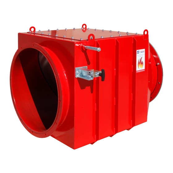
Page 4 Introduction Thank you for purchasing the EcoMAXX® No Return Valve (EM-NRV). The EM-NRV is an Explosion Isolation Device specifically designed to prevent deflagration propagation between connected equipment. The EM-NRV is ATEX certified and NFPA 69 compliant. Required Items for NFPA 69 Compliance: •... -
Page 5: Ecomaxx® Nrv Specifications (Em-Nrvø)
Page 5 EcoMAXX® NRV Specifications (EM-NRVØ) Standard Features (All Sizes) Heavy Duty Welded Steel Construction * Epoxy Powder Coated Safety Red Finish Flanged Inlet and Outlet with Co-Flanges * Grounding Lugs * Locking Mechanism(s) ATEX Certification The NRV can be installed indoors, however the below statement from NFPA must be taken into account during the duct design process. -
Page 6: No Return Valve (Nrv) Dimensions
Page 6 No Return Valve (NRV) Dimensions (SIZES 4” - 16”) (SIZES 18” - 28”) RATED FOR: RATED FOR: Class ST 2 Applications Class ST 2 Applications Kst max 270 bar m/s Kst max 260 bar m/s Pred 0.50 bar Pred 0.50 bar Certification EN 16447 Certification EN 16447... -
Page 7: Flange And Co-Flange Dimensions
Page 7 Flange and Co-Flange Dimensions • I.D. 1 Dimensions are the inner diameter dimensions of the flanges installed on EM-NRV • I.D. 2 Dimensions are the inner di- ameter dimensions of the co-flanges provided with EM-NRV Model # I.D. 1 I.D. -
Page 8: Ecomaxx® Intrinsic Panel Specifications (O-Em-Nrv-Cp03)
Page 8 EcoMAXX® Intrinsic Panel Specifications (O-EM-NRV-CP03) 4 Models Available* All Models Feature • Model: O-EM-NRV-CP03 (1 NRV) • NEMA 4 Enclosure • Model: O-EM-NRV-CP03X2 (Up-to 2 NRVs) • Status lights • Model: O-EM-NRV-CP03X3 (Up-to 3 NRVs) (Green = System OK / RED = System Trouble) •... -
Page 9: Receiving The Ecomaxx® Em-Nrv
Page 9 Receiving The EcoMAXX® EM-NRV • The EcoMAXX® EM-NRV typically ships shrink- wrapped and strapped on a wooden pallet. Custom- er must inspect the equipment for damage upon receipt. If damage is present, receiver must note damaged on the shipping documents in order to file a claim. - Page 10 Page 10 NRV Shipment Parts and Assembly Instructions 4” – 28” Assembly Instructions Step 1: Remove bolt on counter weight mounting shaft using provided Allen wrench. Step 2: Slide counter weight onto mounting shaft, then re-tighten bolt using provided Allen wrench. Step 3: Position counter weight in the locked position of the locking mechanism.
-
Page 11: 32"+ Assembly Instructions (Per Side)
Page 11 NRV Shipment Parts and Assembly Instructions 32”+ Shipment Parts Locking Mechanism (2x) Upper Counter Weight Arm 6x - Breaking Elements (2x) Lower Aircom manual with Counter Weight Arm metric Allen Wrenches 32”+ Assembly Instructions (Per Side) Step 1: Remove bolt and washer. - Page 12 Page 12 Step 3: Secure arm in place by tightening the set screw. Note: You will need to adjust arm once locking mechanism is in place. Step 4: Install Locking mechanism onto the mounting bracket of the EcoMAXX NRV. Note: Ensure the handle is centered in the locking mech- anism.
-
Page 13: Microswitch With Mounting Bolts (O-Em-Nrv-Ms)
Page 13 Microswitch with Mounting Bolts (O-EM-NRV-MS) Step 1: Step 2: Step 3: Secure Microswitch Remove screw and lever. Line up arrows and then insert and tighten the screw. Mounting the Microswitch to the NRV Step 4: Step 5: Mount Microswitch to the locking mechanism using Rotate counterweight arm into the locked position. -
Page 14: Dust Level Sensor With Mounting Flanges (O-Em-Nrv-Dls)
Page 14 Dust Level Sensor with Mounting Flanges (O-EM-NRV-DLS) NRV Side Profile NRV Cut View Mounting the Dust Level Sensor to EcoMAXX NRV Step 1: Step: 2: Step 3: Remove bolt on the bot- Install the first Insert sensor into tom side of the NRV. -
Page 15: General Wiring Schematic For The Ecomaxx® Intrinsic Panel
Page 15 General Wiring Schematic for the EcoMAXX® Cp03 To wire supply power connect line, ground, and neutral wires to terminals L, GND, and N as shown in the General Wiring diagram. NOTE: On the wiring diagram you will notice there are two options provided for connecting to the main system control panel. - Page 16 Page 16 Connect low voltage control wires to terminals 3 and 6 as shown in the General Alarm Configuration wiring diagram. Then use a jumper to connect terminals 4 and 5. Connect low voltage control wires to terminals 3 and 4 as shown in the Individual Alarm Configuration wiring diagram.
-
Page 17: Wiring The Microswitch To The Ecomaxx® Intrinsic Panel
Page 17 Wiring the Microswitch to the EcoMAXX® CP03 Referencing the wiring diagram on page 15, the microswitch is connected using terminals 1 and 2. When looking at the diagram, notice only the black and grey wires are used for the microswitch connection. Connect the black wire to one of the terminals labeled 1. -
Page 18: General Wiring Schematic For The Cp04
Page 18 General Wiring Schematic for the Cp04 (56004-031103) Wiring the Dust Level Sensor to the CP04 Connect the brown wire to terminal 4.1 on the intrinsic relay barrier. Connect the blue wire to terminal 4.3 on the intrinsic relay barrier. -
Page 19: Bypassing The Dust Level Sensor For Inspection Protocol In The Cp04
Page 19 Bypasssing the Dust Level Sensor for Inspection Protocol in the Cp04 In cases where an inspection protocol (NFPA 69: 2019, 12.2.3.4.5.2) is instituted in lieu of a dust level sensor for dust accumulation monitoring inside of an EcoMAXX NRV the following instructions must be followed to ensure the system remains running uninterrupted by a fault alarm. -
Page 20: Ecomaxx® Nrv Spare/Replacement Parts
Flanges and Co-Flanges Flange P/N: EB-FLØ Other replaceable parts not Co-Flange P/N: EB-CFLØ noted may be available but must discussed with Boss Products to insure integrity and functionality of the valve. Locking Mechanism with Mounting Bracket P/N: RP-EM-NRV-LMB EcoMAXX®... -
Page 21: Contact Information
Revision 20: updates to dimensions of body and flanges of nrv to match most recent documentation. Addition of CP04 to manual. © Boss Products, LLC 2018 NRV NA Sup. Manual 2020 - Second Edition - Version 0020 Print date: 6/26/2020...