
Related Manuals for Boss 355AA DN15


Summary of Contents for Boss 355AA DN15
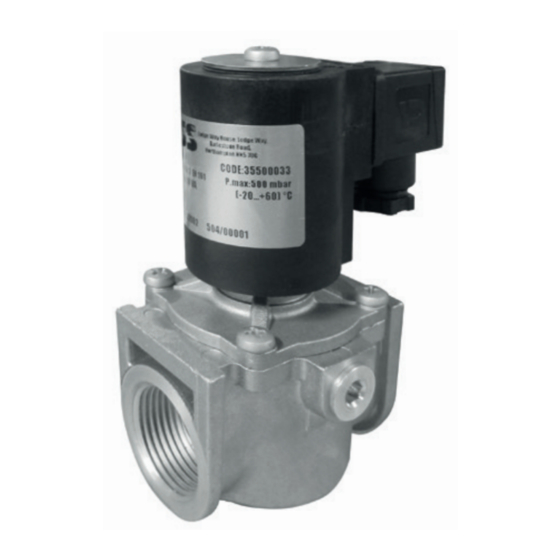
- Page 1 AUTOMATIC NORMALLY CLOSED SOLENOID VALVE FOR GAS 355AA DN 15 - DN 20 - DN 25 CE-51CM4100/ED05 CE-51CT4873/ED05 MADE IN ITALY EC approval according to EN 161, compliant with Regulation (EU) 2016/426...
- Page 2 INDEX pag. English ................................ 3 Drawings ..............................14 Dimensions (table 1) ............................. 16 Spare coils and connectors (table 2) ....................... 17 SIL Level (table 3) ............................18 Diagram ............................... 19...
-
Page 3: General Information
1.0 - GENERAL INFORMATION This manual shows you how to safely install, operate and use the device. The instructions for use ALWAYS need to be available in the facility where the device is installed. ATTENTION: installation/wiring/maintenance need to be carried out by qualified staff (as explained in section 1.3) using appropriate personal protective equipment (PPE). -
Page 4: Qualified Staff
1.3 - QUALIFIED STAFF These are people who: • Are qualified to carry out product installation, assembly, start-up and maintenance; • Know the regulations in force in the region or country pertaining to installation and safety; • Are trained in first aid. 1.4 - USING NON-ORIGINAL SPARE PARTS •... -
Page 5: Technical Data
2.0 - TECHNICAL DATA • Use : non-aggressive gases of the three families (dry gases) • Ambient temperature (TS) : -20 ÷ +60 °C • Supply voltages (see table 2) : 24 V/50 Hz - 110 V/50-60 Hz - 230 V/50-60 Hz* •... -
Page 6: Model Identification
2.1 - MODEL IDENTIFICATION See Table 2 on page 17. 2.2 - SIL LEVEL The SIL level of the stand-alone solenoid valve is SIL 2; when two solenoids are installed in series and the relative leak test (Valve Proving System), certified according to EN 1643, the achieved level is SIL 3, as set forth in EN 676:2008. The solenoid valve has PL d level. - Page 7 3.2 - INSTALLATION (see example in 3.4) • Assemble the device by screwing it, with the correct seals, onto the plant with pipes and/or fittings whose threads are consistent with the connection being attached; • Do not use the coil (11) as a lever to help you screw it on, only use the specific tool; •...
- Page 8 • Connect terminals 1 and 2 to the power supply and the earth cable to terminal • Secure the connector (1) to the coil (11), tightening (recommended tightening torque 0.4 N.m ± 10%) the centre screw (13); • The valve needs to be earthed either through the pipe or through other means (ex. cable jumpers). 3.3 - INSTALLATION IN PLACES WHERE THERE IS THE RISK OF EXPLOSION (DIRECTIVE 2014/34/EU) The solenoid valve is not suitable for use in potentially explosive areas.
- Page 9 3.4 - GENERIC EXAMPLE OF AN INSTALLATION (Burner Gas Train) 1. Gas filter 7. Slow opening automatic solenoid valve 2. OPSO shut off valve 8. External reset 3. Pressure regulator 9. Burner control 4. Minimum pressure switch 10. Valve proving system 5.
-
Page 10: First Start-Up
4.0 - FIRST START-UP • Before start-up make sure that all of the instructions on the rating plate, including the direction of flow, are observed; • After having gradually pressurised the system, check tightness and operation of the solenoid valve, electrically powering / disconnecting the connector ONLY IF connected to the coil. - Page 11 5.1 - REPLACING THE CONNECTOR • Unscrew and remove the central screw (13), then remove the connector (1) from the coil (11); • When you have taken out the existing internal electrical wiring, wire the new connector and secure it to the coil, as shown in 3.2; 5.2 - REPLACING THE COIL •...
-
Page 12: Transport, Storage And Disposal
7.0 - TRANSPORT, STORAGE AND DISPOSAL 6.2 - CPI SWITCH INSTALLATION and CALIBRATION It is necessary to close the gas prior to installation. • During transport the material needs to be handled with care, NOTE: CPI connector (19) wiring must be do ensuring a avoiding any impact or vibrations to the device;... -
Page 13: Rating Plate Data
9.0 - RATING PLATE DATA Lodge Way House, Lodge Way, Harlestone Road, Northampton NN5 7UG. The rating plate data (see example provided here) includes the following: Mod.: 355AA DN 25 CODE: 35500033 CE-51../ED05 Cl.A Gr.2 EN 161 P. max:500 mbar IP65 - 230 V/50-60 Hz 18 VA TS: -20+60 °C •... - Page 14 fig. 1 DN 15-20 P.max 200 mbar...
- Page 15 fig. 2 fig. 3 DN 25 CPI installation P.max 500 mbar...
- Page 16 fig. 1, 2 and 3 11. Electric coil 1. Electric connector 12. Coil fastening screw 13. Connector centre screw 2. Cover sealing O-Ring 3. Closing spring 14. Lower cap (on versions set-up for CPI installation) 4. Valve body 15. Microswitch 16.
- Page 17 Table 2 Coils and connectors Valve code Connections Voltage Coil + connector code Coil stamping Connector type Absorbed power 35500173 Rp DN 15 BO-0410 24 Vac 35500184 Rp DN 20 24 V/50 Hz B13052 14 VA 24 VDC 17W Rectifier 35500195 Rp DN 25 35500642...
- Page 18 Table 3 SIL LEVEL Parameter Value Hardware Failure Tolerance - HFT Common Cause Failure - CCF in points Safe Failure Fraction - SFF in % Expected Lifetime Cycles - B 251278 Expected Lifetime - T [years] Probability of Dangerous Failures - PFH [1/h] 1.33E-07 Performance Level - PL...
- Page 19 Pressure drop diagram (calculated with P1 = 50 mbar) dv = density relative to the air 1) methane 2) air 3) town gas 4) lpg dv = 0,65 dv = 1 dv = 0,47 dv = 1,67...
- Page 20 We reserve the right to any technical and construction changes. Registered Office: Travis Perkins PLC, Lodge Way House, Lodge Way, Harlestone Road, Northampton NN5 7UG. Telephone Number: 0116 245 5500 www.bssindustrial.co.uk - inquiries@bssgroup.com...