Table of Contents

Related Manuals for Boss 355AA


Summary of Contents for Boss 355AA
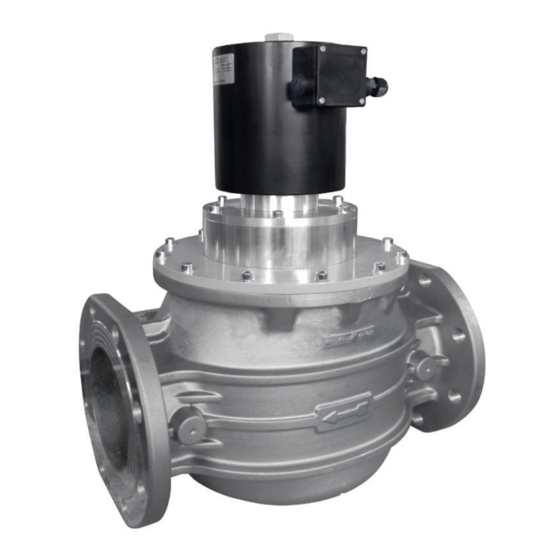
- Page 1 AUTOMATIC NORMALLY CLOSED SOLENOID VALVE FOR GAS 355AA DN 32 - DN 40 - DN 50 - DN 65 - DN 80 DN 100 - DN 125 - DN 150 P.max: 360 mbar CE-51BS3422/ED05 MADE IN ITALY EC approval according to EN 161, compliant with Regulation (EU) 2016/426...
- Page 2 INDEX pag. English ................................ 3 Drawings ..............................13 Dimensions (table 1) ............................. 17 Spare coils and connectors (table 2) ....................... 18 SIL Level (table 3) ............................19 Diagram ............................... 19...
-
Page 3: General Information
1.0 - GENERAL INFORMATION This manual shows you how to safely install, operate and use the device. The instructions for use ALWAYS need to be available in the facility where the device is installed. ATTENTION: installation/wiring/maintenance need to be carried out by qualified staff (as explained in section 1.3) using appropriate personal protective equipment (PPE). -
Page 4: Technical Data
2.0 - TECHNICAL DATA • Use : non-aggressive gases of the three families (dry gases) • Ambient temperature (TS) : -20 ÷ +60 °C • Supply voltages (see table 2) : 24 V/50 Hz - 110 V/50-60 Hz - 230 V/50-60 Hz* •... -
Page 5: Commissioning The Device
3.0 - COMMISSIONING THE DEVICE 3.1 - OPERATIONS PRIOR TO INSTALLATION • It is necessary to close the gas upstream of the valve prior to installation; • Make sure that the line pressure DOES NOT EXCEED the maximum pressure declared on the product label; •... - Page 6 3.2 - INSTALLATION (see examples in 3.4) Threaded devices: • Assemble the device by screwing it, with the correct seals, onto the plant with pipes and/or fittings whose threads are consistent with the connection being attached. • Do not use the coil (4) as a lever to help you screw it on, only use the specific tool; •...
- Page 7 3. Gas filter 10. Gas detector 4. OPSO shut off valve 11. Remote jerk ON/OFF valve lever control 5. Pressure regulator 12. Expansion joint/anti-vibration mount 6. 355AA... fast opening automatic solenoid valve 7. Solenoid valve control device discharge in open air...
-
Page 8: First Start-Up
8. External reset 3. Pressure regulator 9. Burner control 4. Minimum pressure switch 10. Valve proving system 5. 355AA... fast opening automatic 11. Relief valve solenoid valve 12. Pressure gauge and relative button 6. Maximum pressure switch 13. Gas detector... - Page 9 5.1 - CONNECTOR/ELECTRONIC BOARD REPLACEMENT fig. 1 g. Loosen the 4 fastening screws (1) of the cover (2); h. Remove the over (2) and loosen the cable gland (3) with a 22mm commercial spanner; i. Loosen the screws of the main terminal board (31) and remove the existing electric wiring by extracting the cables from the terminal board and cable gland (3);...
- Page 10 5.2 - REPLACING THE COIL III) Threaded bar I) Fastening nut Complete coil II) Washer (including connector/board) supplied as a spare part Remove the fastening ring nut (20) Remove the O-Ring (19) Extract and remove the coil (4) with a 35mm commercial spanner Loosen the nut (I) with a 35mm Now proceed with replacing the coil Remove the coil from the threaded...
- Page 11 5.3 - REPLACING THE FILTER ELEMENT (DN 65 - DN 80 - DN 100 - DN 125 - DN 150) If internal checks must be carried out, before carrying out any operations: • Close the gas upstream of the valve; •...
-
Page 12: Transport, Storage And Disposal
The rating plate data (see example provided here) includes the following: Lodge Way House, Lodge Way, Harlestone Road, Northampton NN5 7UG. • Manufacturer’s name/logo and address Mod.: 355AA DN 80 CODE: 35500088 • Mod.: = device name/model followed CE-51BS3422/ED05 Cl.A Gr.2 EN 161 P. max:360 mbar IP65 - 230 V/50-60 Hz 290/75 VA TS: -20+60 °C... - Page 13 fig. 2 DN 32 - DN 40 - DN 50...
- Page 14 fig. 3 DN 65 - DN 80 - DN 100...
- Page 15 fig. 4 DN 125 - DN 150...
- Page 16 fig. 5 DN 65 - DN 80 - DN 100 fig. 5: view from above without cover Position the filter element (15), making sure it is between the relative guides (34). fig. 6 DN 125 - DN 150 fig. 6: view from above without cover Position the filter element (15), making sure it is inserted between the relative guides (34) and check that the fins (35) are secured well...
- Page 17 fig. 1, 2, 3, 4, 5 and 6 1. Cover fastening screws 12. Sealing washer 26. Microswitch 2. Electrical box cover 13. Bottom (on DN 65-80-100 only) 27. Toothed washer 3. Cable gland 14. Cap G 1/4 28. Connector/board fastening nut 4.
- Page 18 Table 2 Coils and connectors for 355AA solenoid valve Absorbed power Coil + connector code Valve code Connections Voltage Coil stamping Connector type (available as special order) 35500203 Rp DN 32 BO-1015 35500214 Rp DN 40 24 V/50 Hz B13138...
- Page 19 Table 3 SIL LEVEL Parameter Value Hardware Failure Tolerance - HFT Common Cause Failure - CCF in points Safe Failure Fraction - SFF in % Expected Lifetime Cycles - B 251278 Expected Lifetime - T [years] Probability of Dangerous Failures - PFH [1/h] 1.33E-07 Performance Level - PL...
- Page 20 We reserve the right to any technical and construction changes. Registered Office: Travis Perkins PLC, Lodge Way House, Lodge Way, Harlestone Road, Northampton NN5 7UG. Telephone Number: 0116 245 5500 www.bssindustrial.co.uk - inquiries@bssgroup.com...